manuals.online logo
Brands
  1. Home
  2. •
  3. Brands
  4. •
  5. Ferroli
  6. •
  7. Test Equipment
  8. •
  9. Ferroli UT REC R+ User manual

Ferroli UT REC R+ User manual

This manual suits for next models

1

Popular Test Equipment manuals by other brands

Ambit P.F. Series instruction manual

Ambit

Ambit P.F. Series instruction manual

Megger BMM500 Series user guide

Megger

Megger BMM500 Series user guide

RJG Lynx Sensor Tester operating instructions

RJG

RJG Lynx Sensor Tester operating instructions

Mark-10 TT02 Series user guide

Mark-10

Mark-10 TT02 Series user guide

Martel 3001 Operator's manual

Martel

Martel 3001 Operator's manual

ElproSys DiagProg4 instruction manual

ElproSys

ElproSys DiagProg4 instruction manual

Redtech TRAILERteck T05 user manual

Redtech

Redtech TRAILERteck T05 user manual

Venmar AVS Constructo 1.0 HRV user guide

Venmar

Venmar AVS Constructo 1.0 HRV user guide

Test Instrument Solutions SafetyPAT operating manual

Test Instrument Solutions

Test Instrument Solutions SafetyPAT operating manual

Hanna Instruments HI 38078 instruction manual

Hanna Instruments

Hanna Instruments HI 38078 instruction manual

Kistler 5495C Series instruction manual

Kistler

Kistler 5495C Series instruction manual

Waygate Technologies DM5E Basic quick start guide

Waygate Technologies

Waygate Technologies DM5E Basic quick start guide

StoneL DeviceNet CK464002A manual

StoneL

StoneL DeviceNet CK464002A manual

Seica RAPID 220 Site preparation guide

Seica

Seica RAPID 220 Site preparation guide

Kingfisher KI7400 Series Training manual

Kingfisher

Kingfisher KI7400 Series Training manual

Kurth Electronic CCTS-03 operating manual

Kurth Electronic

Kurth Electronic CCTS-03 operating manual

SMART KANAAD SBT XTREME 3G Series user manual

SMART

SMART KANAAD SBT XTREME 3G Series user manual

Agilent Technologies BERT Serial Getting started

Agilent Technologies

Agilent Technologies BERT Serial Getting started

manuals.online logo
manuals.online logoBrands
  • About & Mission
  • Contact us
  • Privacy Policy
  • Terms and Conditions

Copyright 2025 Manuals.Online. All Rights Reserved.

UT REC R+ / UT REC RE+
MANUALE DI ISTALLAZIONE, USO E MANUTENZIONE /
INSTALLATION, USE AND MAINTENANCE MANUAL
UNITÀ A RECUPERO TOTALE CON SCAMBIATORE ROTATIVO
HENTHALPY WHEEL HEAT RECOVERY UNITS
Manuale di installazione, Uso e Manutenzione - Installation, Use and Maintenance Manual
pag. 2
INDICE INDEX
1 - SIMBOLOGIA UTILIZZATA pag. 3
2 - AVVERTENZE E REGOLE GENERALI pag. 3
3 - IDENTIFICAZIONE UNITÀ pag. 5
4 - CARATTERISTICHE TECNICHE pag. 6
4.1 Caratteristiche generali pag. 6
4.2 Accessori pag. 6
4.3 Dati tecnici unità pag. 7
4.4 Orientamenti possibili pag. 8
4.5 Funzionalità principali pag. 9
4.6 Dimensioni e pesi pag. 10
5 - TRASPORTO pag. 11
6 - SCARICO pag. 11
6.1 Controllo al ricevimento pag. 11
6.2 Sollevamento e movimentazione pag. 11
6.3 Stoccaggio pag. 11
7 - INSTALLAZIONE E MESSA IN SERVIZIO pag. 12
7.1 Definizioni pag. 12
7.2 Norme di sicurezza pag. 12
7.3 Informazioni preliminari pag. 13
7.4 Luogo d'installazione pag. 13
7.5 Posizionamento della macchina pag. 14
7.6 Collegamento ai canali aeraulici pag. 14
7.7 Collegamenti idraulici pag. 14
7.8 Sezione con batteria ad acqua SBFR pag. 15
8 - COLLEGAMENTI ELETTRICI pag. 17
8.1 Accessori e caratteristiche elettriche pag. 17
8.2 Schemi elettrici pag. 24
9 - CONTROLLI PRIMA DELL'AVVIAMENTO pag. 34
10 - MANUTENZIONE ORDINARIA pag. 34
10.1 Avvertenze pag. 34
10.2 Controlli mensili pag. 34
10.4 Controlli annuali pag. 35
11 - LOCALIZZAZIONE DEI GUASTI pag. 35
12 - SMALTIMENTO pag. 35
INDEX
1 - SYMBOLS USED page 3
2 - WARNINGS AND GENERAL RULES page 3
3 - IDENTIFICATION OF THE UNIT page 5
4 - TECHNICAL SPECIFICATIONS page 6
4.1 General characteristics page 6
4.2 Options page 6
4.3 Unit technical data page 7
4.4 Possible configurations page 8
4.5 Main logic control page 9
4.6 Dimensions and whights page 10
5 - TRANSPORT page 11
6 - UNLOADING page 11
6.1 Checks upon receipt page 11
6.2 Hoisting and handling page 11
6.3 Storage page 11
7 - INSTALLATION AND START UP page 12
7.1 Definitions page 12
7.2 Safety Standards page 12
7.3 Preliminary information page 13
7.4 Installation location page 13
7.5 Unit positioning page 14
7.6 Horizontal units positioning page 14
7.7 Hydraulic connections page 14
7.8 Water coil section SBFR page 15
8 - ELECTRIC CONNECTIONS page 17
8.1 Options and technical feateures page 17
8.2 Series wiring diagrams page 24
9 - CHECK BEFORE START-UP page 34
10 - ORDINARY MAINTENANCE page 34
10.1 Warnings page 34
10.2 Montly checks page 34
10.4 Yearly checks page 35
11 - TROUBLESHOOTING page 35
12 - DISPOSAL page 35
IMPORTANTE
PRIMA DI COMPIERE QUALUNQUE OPERAZIONE
RIGUARDANTE LA MACCHINA LEGGERE
ATTENTAMENTE, COMPRENDERE E SEGUIRE
TUTTE LE ISTRUZIONI DEL PRESENTE MANUALE
IMPORTANT
BEFORE PERFORMING ANY OPERATION OF THE
MACHINE CAREFULLY READ,
UNDERSTAND AND FOLLOW
ALL INSTRUCTIONS LISTED IN THIS MANUAL
Manuale di installazione, Uso e Manutenzione - Installation, Use and Maintenance Manual pag. 3
1 - SIMBOLOGIA UTILIZZATA 1 - SYMBOLS USED
AVVERTENZA WARNING
PERICOLO DANGER
PERICOLO RISCHIO DI SCOSSE ELETTRICHE DANGER RISK OF ELECTRIC SHOCK
ATTENZIONE SOLO PERSONALE AUTORIZZATO ATTENTION ONLY AUTHORISED STAFF
DIVIETO PROHIBITION
La macchina è stata progettata e costruita in accordo alle norme vigenti ed
è quindi dotata di sistemi di prevenzione e protezione per i rischi di natura
meccanica ed elettrica che possono riguardare l’operatore o l’utilizzatore.
Vi sono tuttavia dei rischi residui che possono presentarsi durante il tra-
sporto, l’installazione, l’uso o la manutenzione. Tali rischi possono essere
ridotti seguendo scrupolosamente le istruzioni del manuale, utilizzando gli
adeguati dispositivi di protezione individuali e rispettando le vigenti norme
di sicurezza.
Le indicazioni più importanti riguardanti la sicurezza e il corretto utilizzo
della macchina sono accompagnate da alcuni simboli per renderle più evi-
denti:
The machine has been designed and constructed according to the current
norms and consequently with mechanical and electrical safety devices
designed to protect the operator or user from possible physical damage.
Residual risks during use or in some intervention procedures on the devi-
ce are however present. Such risks can be reduced by
carefully following manual procedures, using the suggested individual pro-
tection devices and respecting the legal and safety norms in force.
The most important information concerning safety and proper use of the
machine are accompanied by some symbols to make them highly visible:
Questo libretto d'istruzione è parte integrante dell'apparecchio e di conse-
guenza deve essere conservato con cura e dovrà SEMPRE accompagna-
re l'apparecchio anche in caso di sua cessione ad altro proprietario o uten-
te oppure di un trasferimento su un altro impianto. In caso di suo danneg-
giamento o smarrimento richiederne un altro esemplare alla Ditta
Costruttrice.
This instruction book is an integral part of the appliance and as a
consequence must be kept carefully and must ALWAYS accom-
pany the appliance even if transferred to other owners or users
or transferred to another plant. If damaged or lost, request ano-
ther copy from the Manufacturer.
Gli interventi di riparazione o manutenzione devono essere eseguiti da
personale autorizzato o da personale qualificato secondo quanto previ-
sto dal presente libretto. Non modificare o manomettere l'apparecchio in
quanto si possono creare situazioni di pericolo ed il costruttore dell'ap-
parecchio non sarà responsabile di eventuali danni provocati.
Repair and maintenance interventions must be carried out by
authorised staff or staff qualified according to that envisioned by
this book. Do not modify or tamper with the appliance as dange-
rous situations can be created and the appliance manufacturer
will not be liable for any damage caused.
Dopo aver tolto l'imballo assicurarsi dell'integrità e della completezza del
contenuto. In caso di non rispondenza rivolgersi alla Ditta che ha vendu-
to l'apparecchio.
After having removed the packaging ensure the integrity and
completeness of the content. If this is not the case, contact the
Company that sold the appliance.
L'installazione degli apparecchi deve essere effettuata da impresa abili-
tata che, a fine lavoro, rilasci al proprietario la dichiarazione di confomità
di installazione realizzata a regola d'arte, cioè in ottemperanza alle
Norme vigenti ed alle indicazioni fornite in questo libretto.
The appliances must be installed by enabled companies which, at
the end of the job issues a declaration of conformity regarding
installation to the owner, i.e. in compliance with the Standards in
force and the indications supplied in this book.
È esclusa qualsiasi responsabilità contrattuale ed extracontrattuale della
Ditta Costruttrice per danni causati a persone, animali o cose, da errori
di installazione, di regolazione e di manutenzione o da usi impropri.
Any contractual or extracontractual liability of the Manufacturer is
excluded for injury/damage to persons, animals or objects owing
to installation, regulation and maintenance errors or improper
use.
2 - AVVERTENZE E REGOLE GENERALI 2 - WARNINGS AND GENERAL RULES
Manuale di installazione, Uso e Manutenzione - Installation, Use and Maintenance Manual
pag. 4
Ricordiamo che l'utilizzo di prodotti che impiegano energia elettrica ed acqua, comporta
l'osservanza di alcune regole fondamentali di sicurezza quali:
We remind you that the use of products that employ electrical energy and
water requires that a number of essential safety rules be followed, including:
È vietato l'uso dell'apparecchio ai bambini e alle persone inabili non
assistite.
This appliance must not be used be children and unaided dis-
abled persons.
È vietato toccare l'apparecchio se si è a piedi nudi e con parti del corpo
bagnate o umide.
It is prohibited to touch the appliance when you are barefoot
and with parts of the body that are wet or damp.
È vietata qualsiasi operazione di manutenzione o di pulizia, prima di
aver scollegato l'apparecchio dalla rete di alimentazione elettrica posi-
zionando l'interruttore generale dell'impianto su "spento".
It is prohibited to perform any maintenance or cleaning opera-
tion before having disconnected the appliance from the
mains electricity network, by positioning the plant master switch
at "off"
È vietato modificare i dispositivi di sicurezza o di regolazione senza
l'autorizzazione e le indicazioni del costruttore dell'apparecchio.
It is prohibited to modify the safety or adjustment devices
without the manufacturer’s authorisation and precise instruc-
tions
È vietato tirare, staccare, torcere i cavi elettrici fuoriuscenti dall'apparec-
chio, anche se questo è scollegato dalla rete di alimentazione elettrica.
It is prohibited to pull, detach or twist the electrical cables
coming from the unit even if it is disconnected from the electri-
cal mains
È vietato salire con i piedi sull'apparecchio, sedersi e/o appoggiarvi
qualsiasi tipo di oggetto.
It is prohibited to climb onto the unit, sit on it and/or rest any
type of object on it.
È vietato spruzzare o gettare acqua direttamente sull'apparecchio.
It is prohibited to spray or jet water directly onto the unit.
È vietato aprire gli sportelli di accesso alle parti interne dell'apparec-
chio, senza aver prima posizionato l'interruttore generale dell'impianto
su "spento" .
It is prohibited to open the doors for accessing the internal parts
of the appliance without first having switched off the master
switch of the "system".
È vietato disperdere, abbandonare o lasciare alla portata di bambini il
materiale dell'imballo in quanto può essere potenziale fonte di pericolo.
It is prohibited to disperse, abandon or leave the packing mate-
rials within the reach of children, as they are a potential
source of danger
Poiché la Ditta Costruttrice è costantemente impegnata nel conti-
nuo perfezionamento di tutta la sua produzione, le caratteristiche
estetiche e dimensionali, i dati tecnici, gli equipaggiamenti e gli
accessori, possono essere soggetti a variazione.
Per tale motivo il produttore si riserva di apportare qualsiasi
modifica senza preavviso.
As our Company is constantly involved in the continuous impro-
vement of its production, aesthetic characteristics and dimen-
sions, technical data, equipment and accessories can be subject
to variation. For this reason the manufacturer reserves the right
to make any changes without prior notice.
NOTE IMPORTANTI
Le unità sono progettate e costruite esclusivamente per:
- installazioni interne, salvo adottare idonei accessori che ne con-
sentano l’installazione all’aperto;
- per il trattamento aria degli ambienti civili, incompatibili con gas
tossici, esplosivi, infiammabili e corrosivi (incluse atmosfere con
cloro e salsedine).
Quindi se ne fa esplicito divieto di utilizzo in quegli ambienti dove
l'aria risulti mescolata e/o alterata da altri composti gassosi e/o
particelle solide.
L'utilizzo per scopi diversi da quelli previsti, e non conformi a
quanto descritto in questo manuale, farà decadere automatica-
mente qualsiasi responsabilità diretta e/o indiretta della Ditta
Costruttrice e dei suoi Distributori.
IMPORTANT NOTES
The units are designed and built exclusively for:
- internal installation, except to use specific option for outdoor
installation;
- for air traitment in the civil environments, incompatible with
toxic, explosive, inflammable and corrosive (chlorinated and sali-
ne included) gases.
Therefore it cannot be used in those environments where the air
is mixed and/or altered by other gaseous composites and/or solid
particles.
The use of the same for different purposes from those envisioned,
not conform to that described in this manual, will make any direct
and/or indirect liability of the Manufacturer automatically become
null and void.
Manuale di installazione, Uso e Manutenzione - Installation, Use and Maintenance Manual
pag. 5
3 - IDENTIFICAZIONE UNITÀ 3 - IDENTIFICATION OF THE UNIT
PER EVENTUALI RICHIESTE DI INFOMAZIONI E’ NECESSARIO
RIVOLGERSI ALLA SEDE COMUNICANDO IL NUMERO DI SERIE
DELL’UNITA’.
WHEN CONTACTING THE OFFICE FOR ANY INFORMATION ENQUI-
RIES, PLEASE PROVIDE THE UNIT SERIAL NUMBER.
Le unità sono dotate di una targhetta di identificazione che riporta:
A - Marchio del Costruttore;
B - Indirizzo del Costruttore;
C - Modello unità;
D - Matricola unità;
E - Tensione; n° fasi; frequenza di alimentazione;
F - Corrente assorbita massima;
G - Codice unità;
H - Data di produzione;
I - Marcatura “CE”;
L - Codice a barre identificativo
The units feature a rating plate that describes the following:
A - Mark of the manufacturer;
B - Address of the manufacturer;
C - Unit model;
D - Unit serial number;
E - Voltage, number of phases; frequency of the power supply;
F - Max absorbed current;
G - Unit code;
H - Manufacturinga date;
I - “CE” mark;
L - Bar code
B
A
C
D
E
F
G
H
I
L
Manuale di installazione, Uso e Manutenzione - Installation, Use and Maintenance Manual pag. 6
4.2 Accessori
• Sezione con resistenza elettrica di post-riscaldamento - BER
• Sezione di post-riscaldamento ad acqua - BCR
• Sezione con batteria ad acqua promiscua - SBFR
• Filtri ad alta efficienza in espulsione - F7CF
• Pressostato filtri addizionale - PF
• Serranda di regolazione - SR
• Sezione 3 serrande di sbrinamento - RMS
• Servomotori per serrande - SM / SMR
• Kit gestione Bypass - KBP
• Kit n° 4 attacchi circolari - SPC
• Silenziatori da canale - SSC
• Kit lampade di segnalazione (Legge “antifumo” n° 3/2003) - KLS
• Termostato antigelo - TA
• Pannello di controllo velocità (Solo per UTREC R+) - COM 3
• Pannello di controllo unità - PCU / PCUE
• Sistema di gestione integrale a bordo macchina - SIGB
• Sistema di gestione integrale con quadro a parete - SIGQ
Istruzioni del manuale dedicato fornito a corredo con l’unità
dotata di tale accessorio.
• Scheda Modbus per SIGB / Q - SCMB
• Regolazione ventilatori a portata costante (UTREC RE+ 100400) - VSD
• Sensore di CO2- QSC / QSA
• Sensore di umidità - USD / USW
• Kit installazione da esterno - EXT
• Kit cuffie da esterno - CPA
4.2 Options
• Electric post-heating section - BER
• Post-heating water coil section - BCR
• Water cooling or heating coil section - SBFR
• High efficiency filters on exhaust air - F7CF
• Additional pressure switch - PF
• Regulation damper - SR
• 3 dampers defrosting section - RMS
• Damper actuators - SM / SMR
• Kit bypass management - KBP
• N. 4 connections for circular ducts kit - SPC
• Duct silencers - SSC
• Signal lamps kit - KLS
• Anti-freeze thermostat - TA
• Unit speed control panel (Only for UT‐REC R+) - COM 3
• Unit control panel - PCU / PCUE
• Integrated management system on board - SIGB
• Integrated management system wall mount box - SIGQ
Use specific manual supplied on the unit with this option
• Modbus PCB for SIGB / Q - SCMB
• Constant air flow fans control (UT‐REC RE+ 100‐400) - VSD
•CO
2sensor - QSC / QSA
• Humidity sensor - USD / USW
• Kit for external installation - EXT
• Kit weather hood for external installation - CPA
4 - CARATTERISTICHE TECNICHE
4.1 CARATTERISTICHE GENERALI
• Pannelli sandwich laterali rimovibili in lamiera preverniciata.
• Isolamento acustico e termico dei pannelli tramite polietilene/poliestere
con spessore medio di 23 mm.
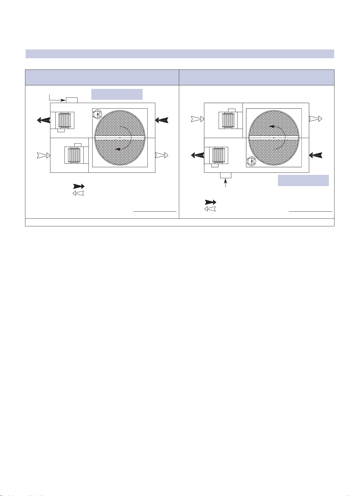
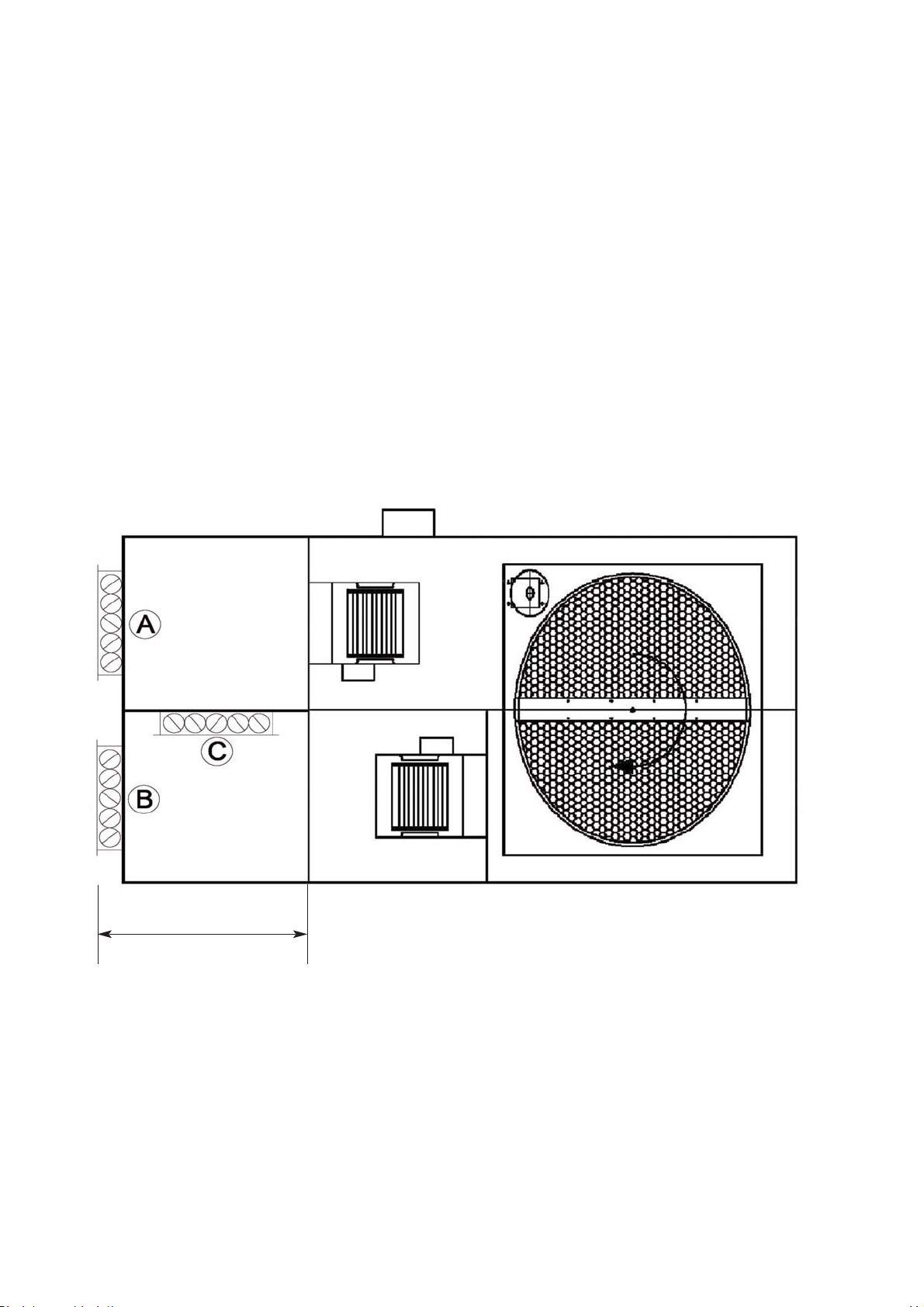
• Recuperatore di calore ad alto rendimento di tipo rotativo in alluminio
con superficie igroscopica (setaccio molecolare). I flussi d’aria sono
mantenuti separati da apposite guarnizioni. Motore elettrico ad induzio-
ne con trasmissione del moto al rotore mediante cinghia e puleggia.
• Gruppo recuperatore-motore facilmente estraibile lateralmente per la
manutenzione periodica.
• Ventilatori di presa aria di rinnovo e di espulsione di tipo centrifugo a
doppia aspirazione. Motore elettrico direttamente accoppiato di tipo EC
in UTREC RE+.
• Corpo ventilante montato su antivibranti per non trasmettere eventuali vibrazioni.
• Filtri aria standard con efficienza F7 in mandata ed M5 in ripresa, facil-
mente estraibili lateralmente allo scopo di permettere la loro periodica
pulizia.
• Pressostato filtri aria di rinnovo con segnalazione visiva allarme filtro
sporco.
• Morsettiere a bordo macchina per facilitare i collegamenti elettrici, il
controllo dei ventilatori e il controllo del recuperatore rotativo.
4 - TECHNICAL SPECIFICATIONS
4.1 GENERAL CHARACTERISTICS
• Side sandwich paneling made of painted metal sheet, removable.
• An average 23 mm-thick layer of polyethylene and polyester is installed
in the unit to ensure acoustic and heat insulation.
• Rotary, high efficiency heat exchanger with hygroscopic surface (mole-
colar sieve). Air flows separation by special gaskets. Induction motor
with belt transmission to the rotary heat exchanger.
• Induction motor-heat exchanger assembly easily sideways removable.
• The dual intake centrifugal fans have statically and dynamically balan-
ced impellers to minimise vibrations and noise. The electric motors
used are directly coupled to the fans; they are EC type in UT‐REC RE+
series.
• Vibration absorbing supports to ensure low noise level.
• Standard F7 efficiency filters for supply air flow and M5 for exhaust air
flow, easily removable from the sides for periodical cleaning.
•Pressure switch for fresh air filters with visual filter change warning light
indicator.
• The units are fitted with terminal boards to simplify the electrical con-
nections,the fans and rotary exchanger control.
Manuale di installazione, Uso e Manutenzione - Installation, Use and Maintenance Manual
pag. 7
4.3 Dati tecnici unità 4.3 Unit technical data
(1) Multiple = Multivelocità > 3
Man = Manuale da selettore o tastiera; 0-10V = Da potenziometro o tastiera;
VSD = A portata costante o modulazione da sensore qualità/umidità aria
(2) Livello di potenza sonora alle condizioni di funzionamento nominali
(3) Aria esterna -5°C 80% UR; aria ambiente 20°C 50% UR
(4) Aria esterna 32°C 50% UR; aria ambiente 26°C 50% UR
(5) Secondo regolamento UE 1253/2014: alla pressione nominale;
condizioni di temperatura e umidità riferite a EN 308
(1) Multiple = Multispeed > 3
Man = Manual by selector switch or control panel; 0-10V = By potentiometer or control
panel; VSD = Constant flow control or modulation by air quality or air humidity sensor
(2) Sound power level at nominal working conditions
(3) Outside air at -5° 80% RH; room air at 20°C 50% RH
(4) Outside air at 32° 50% RH; room air at 26°C 50% RH
(5) Refeer to EU 1253/2014 regulation: at nominal pressure; air conditions refer to EN
308 standard
MODELLO / MODEL 40 40 E 75 75 E 100 100 E 150 150 E 200 200 E 320 320 E 400 400 E
Portata aria nominale / Nominal air flow m3/h 310 310 640 640 1000 1000 1650 1650 2400 2400 3200 3200 3800 3800
Pressione statica utile nominale / Nominal external
static pressure Pa 230 230 130 130 190 190 160 160 300 300 180 180 100 100
Pressione statica utile massima / Maximum external
static pressure Pa 230 430 130 280 190 560 160 600 300 480 180 460 100 240
Alimentazione elettrica / Electrical power supply V/ph/Hz 230 / 1 / 50 230 / 1 / 50-60
Potenza assorbita massima totale / Total full load
power input kW 0.38 0.59 0.71 0.59 1.44 2.14 1.44 2.14 3.33 2.16 3.33 2.39 3.33 2.39
Corrente assorbita massima totale / Total full load
amperage A 1.7 2.6 3.1 2.6 6.2 9.2 6.2 9.2 14.3 9.3 14.3 10.3 14.3 10.3
LIMITI OPERATIVI / WORKING LIMITS
Condizioni di temperatura - umidità limite esterne /
Outdoor temperature - humidity working limits °C / % -5 … +45 °C / 5 … 95%
Condizioni di temperatura - umidità limite esterne
con accessorio RMS / Outdoor temperature - humi-
dity working limits with RMS option
°C / % -15 … +45 °C / 5 … 95%
Condizioni di temperatura - umidità limite interne /
Indoor temperature - humidity working limits °C / % +10 … +35 °C / 10 … 90%
VENTILATORI / FANS 40 40 E 75 75 E 100 100 E 150 150 E 200 200 E 320 320 E 400 400 E
Tipologia motore / Motor typology AC EC AC EC AC EC AC EC AC EC AC EC EC EC
N° velocità / Number of speeds (1) 3 Multiple 3 Multiple 3 Multiple 3 Multiple 3 Multiple 3 Multiple Multiple Multiple
Controllo ventilazione / Fan control (1) Man 0-10V Man 0-10V Man 0-10V
VSD Man 0-10V
VSD Man 0-10V
VSD Man 0-10V
VSD
0-10V
VSD
0-10V
VSD
Potenza assorbita nominale totale / Total nominal
power input kW 0.15 0.14 0.34 0.29 0.63 0.49 0.80 0.66 1.66 1.31 2.04 1.20 1.59 1.48
Corrente assorbita nominale totale / Total nominal
load amperage A 0.6 0.6 1.4 1.2 2.7 2.1 3.4 2.8 7.1 5.6 8.7 5.1 6.8 6.3
Efficienza statica dei ventilatori secondo (UE)
n.327/2011 / Static efficiency of fans %N.A. 32.73% 38.60% 32.73% 38.60% 53.20% 38.60% 53.20% 40.40% 55.90% 43.40% 59.80% 43.40% 59.80%
RECUPERATORE DI CALORE / HEAT EXCHAN-
GER 40 40 E 75 75 E 100 100 E 150 150 E 200 200 E 320 320 E 400 400 E
Efficienza termica invernale / Winter thermal effic. (3) % 79.0% 79.0% 74.0% 74.0% 73.0% 73.0% 74.0% 74.0% 75.0% 75.0% 74.3% 74.3% 73.5% 73.5%
Efficienza entalpica invernale / Winter enthalpy effic.
(3) % 74.0% 74.0% 69.0% 69.0% 58.0% 58.0% 60.0% 60.0% 62.0% 62.0% 60.2% 60.2% 59.0% 59.0%
Potenza termica totale recuperata / Total heating
recovery capacity (3) kW 2.02 2.02 3.90 3.90 6.02 6.02 10.07 10.07 14.84 14.84 19.60 19.60 23.02 23.02
Temperatura aria mandata / Supply air temperature
(3) °C 14.8 14.8 13.5 13.5 13.3 13.3 13.5 13.5 13.8 13.8 13.6 13.6 13.4 13.4
Efficienza termica estiva / Summer thermal effic. (4) % 79.0% 79.0% 74.0% 74.0% 73.0% 73.0% 75.0% 75.0% 81.0% 81.0% 75.0% 75.0% 73.0% 73.0%
Efficienza entalpica estiva / Summer enthalpy effic.
(4) % 69.0% 69.0% 65.0% 65.0% 59.0% 59.0% 60.0% 60.0% 65.0% 65.0% 59.5% 59.5% 59.0% 59.0%
Potenza frigorifera totale recuperata / Total cooling
recovery capacity (4) kW 0.49 0.49 0.95 0.95 1.47 1.47 2.49 2.49 3.91 3.91 4.83 4.83 5.58 5.58
Temperatura aria mandata / Supply air temperature
(4) °C 27.3 27.3 27.6 27.6 27.6 27.6 27.5 27.5 27.1 27.1 27.5 27.5 27.6 27.6
Efficienza termica a secco / Dry thermal effi-
ciency (5) %74.2% 74.2% 74.0% 74.0% 73.0% 73.0% 73.0% 74.0% 73.7% 73.7% 74.3% 74.3% 73.0% 73.0%
Livello di potenza sonora irradiato dall'involucro /
Sound power level (LWA) dB(A) 56 55 58 57 62 61 64 60 68 66 67 64 67 64
Manuale di installazione, Uso e Manutenzione - Installation, Use and Maintenance Manual pag. 8
ORIENTAMENTI MODELLI / MODELS CONFIGURATIONS
4.4 Orientamenti possibili
In funzione della configurazione della rete e dello spazio disponibile è pos-
sibile scegliere, fra due possibili orientamenti, come di seguito illustrato.
4.4 Possibile configurations
According to the configuration of the installation and the space available,
s one of two possible layouts can be chosen, as shown below.
ORIENTAMENTO TIPO 01 / CONFIGURATION TYPE 01
(Tipo standard / Standard type)ORIENTAMENTO TIPO 02 / CONFIGURATION TYPE 02
Gli orientamenti raffigurati sono relativi alla macchina vista dall’alto / The configurations are referred to the top view
Aria espulsa / Exhaust air
Aria di rinnovo / Fresh air
Aria espulsa / Exhaust air
Aria di rinnovo / Fresh air
LATO ESTRAZIONE ROTORE
EXCHANGER EXTRACTION SIDE
LATO ESTRAZIONE ROTORE
EXCHANGER EXTRACTION SIDE
Quadro elettrico / Electrical board
Lato destro / Right sideLato destro / Right side
Quadro elettrico / Electrical board
Manuale di installazione, Uso e Manutenzione - Installation, Use and Maintenance Manual
pag. 9
Dispositivo by pass per free cooling / heating
Quando la temperatura esterna è prossima alla temperatura interna si
può ridurre sensibilmente lo scambio di calore attraverso il recuperatore
rotativo: questo avviene arrestando la ruota annullando lo scambio ter-
mico tra i due flussi.
La macchina base viene fornita predisposta di contatti in morsettiera per
l’alimentazione separata del motore della ruota, pertanto è possibile
gestire il free cooling / heating con un sistema logico completamente
esterno.
In alternativa, con l’accessorio KBP vengono installate le sonde di tem-
peratura e un relè di consenso per la gestione dell’attivazione e arresto
della ruota in funzione delle condizioni climatiche.
Il segnale di attivazione è gestito dalla regolazione elettronica integrata
per unità dotate di controllore PCU / PCUE / SIG (opzionale).
Bypass device for free cooling / heating
When the air intake temperature is near the air outlet temperature the
heat recovery exchanger can be partly bypassed reducing the heat
exchange: switching off the rotative wheel the heat exchange is stopped.
The basic unit is equipped with a connecting terminal for distinct power
supply of fans and wheel motor, therefore it is possible to manage free-
cooling/heating operation by an external control.
As an alternative, with KBP option temperature probes and a control
relay are installed in the unit in order to switch on or off the wheel rota-
tion in function of the climatic conditions.
The activation signal can be managed by the integrated control
PCU / PCUE / SIG (optional).
Sbrinamento. Nei periodi molto freddi l’aria di ripresa ambiente potreb-
be brinare ostruendo il passaggio attraverso il recuperatore. Installando
un pressostato aggiuntivo e l’accessorio RMS è possibile gestire lo sbri-
namento del recuperatore. Infatti se il pressostato rileva una caduta di
pressione eccessiva dovuta alla brina che ostruisce il recuperatore, le
serrande A e B si chiudono e si apre la serranda C. In questo modo l’a-
ria calda di ripresa ambiente viene ricircolata consentendo un rapido
scongelamento del recuperatore stesso che può successivamente tor-
nare al funzionamento normale.
Defrost. When the intake air is very cold, frost may form on the heat
recovery unit.
By installing an additional pressure switch with the RMS accessory, the
heat recovery defrosting can be controlled.
When the pressure loss registered by the pressure switch is too high, the
dampers A and B will close and the damper C will open.
So the warm return air is recirculated, allowing the heat exchanger defro-
sting. Afterwards the unit functioning will become normal.
4.5 Funzionalità principali 4.5 Main logic control
H
Manuale di installazione, Uso e Manutenzione - Installation, Use and Maintenance Manual pag. 10
4.6 Dimensioni e pesi
Dimensioni modelli UTREC R+ / UTREC RE+
4.6 Dimensions and weights
Dimensions of the models UT‐REC R+ / UT‐REC RE+
Aria espulsa
Exhaust air
Aria di rinnovo
Fresh air
Orientamento 1 / Configuration 1
Orientamento 2 / Configuration 2
Dimensione / Dimension Peso /
Weight
Modello
Model
A
[mm]
B
[mm]
C
[mm]
D
[mm]
D1
[mm]
E
[mm]
E1
[mm]
F
[mm]
F1
[mm]
G
[mm]
G1
[mm]
H
[mm]
H1
[mm]
K
[mm]
[Kg]
40 1075 480 800 200 230 210 210 130 160 140 110 110 90 500 70
75 1075 480 800 200 230 210 210 130 160 140 110 110 90 500 75
100 1205 550 1000 300 225 310 255 60 115 180 165 125 145 500 105
150 1400 550 1000 300 225 310 255 60 115 180 165 110 145 600 140
200 1720 680 1290 400 325 410 280 157 200 113 200 125 150 620 180
320 1940 680 1500 400 325 410 280 157 200 113 200 180 220 700 230
400 1940 680 1500 400 325 410 280 157 200 113 200 180 220 700 250