Tenma 72-8355 User manual

1
Model: 72-8355
Constant Power Switch Mode Bench PSU

2
When using electrical appliances, basic safety precautions should always
be followed to reduce the risk of re, electric shock and injury to persons or
property.
Read all instructions before using the appliance and retain for future reference.
• Check that the voltage indicated on the rating plate corresponds with that of the
local network before connecting the appliance to the mains power supply.
• Do not operate this appliance with a damaged plug or cord, after a malfunction or
after being dropped or damaged in any way.
• Check the product before use for any damage. Should you notice any damage on
the cable or casing, do not use.
• This appliance contained no user-serviceable parts. All repairs should only be
carried out by a qualied engineer. Improper repairs may place the user at risk of
harm.
• This product must be grounded through the earth connection in the mains lead for
safe operation and to reduce ripple and noise.
• This product is for indoor use only.
• Avoid touching the exposed metal of the output terminals.
• Do not block or obstruct any cooling vent opening.
• Avoid severe impacts or rough handling that leads to damage.
• Do not discharge static electricity.
• This appliance can be used by children aged from 8 years and above and persons
with reduced physical, sensory, or mental capabilities or lack of experience and
knowledge if they have been given supervision or instruction concerning use of the
appliance in a safe way and understand the hazards involved.
• Children should be supervised to ensure that they do not play with the appliance.
• Always disconnect from the mains when the product is not in use or before
cleaning.
• Do not use the appliance for any purpose other than that for which it is designed.
• Do not operate or store in an environment of high humidity or where moisture may
enter the product as this can reduce insulation and lead to electric shock.
IMPORTANT SAFETY INFORMATION
PRODUCT OVERVIEW
Main Features
• • Efcient switch mode design
• • Extremely compact footprint
• • Remote sensing
• • Four digit LED display
• • Simultaneous display of voltage and current
• • Auto selecting constant voltage (CV) and constant current (CC) modes
• • Ultra quiet convection cooling
• • Short circuit, overload, over voltage and thermal protection
• • 75% efciency at maximum output
WHAT’S INCLUDED
• Power Supply Unit
• Mains power lead
• User Manual

3
Front panel controls
1. POWER – Master on/off selector
2. OUTPUT– Power output terminals
3. UVL – Recessed screw adjustment for UVL (upper voltage limit)
4. CURR – Current limit adjustment
5. VOLT – Output voltage adjustment
6. UVL/VOLTAGE – Press to view upper voltage limit
7. REVIEW – Press to display voltage and current limit settings
8. RANGE – Select desired output voltage and current range
9. OUTPUT ON – Activates supply output
10. UVL – Upper Voltage Limit Indicator, illuminates when UVL is displayed
11. C.V. – Constant Voltage Indicator, illuminates when supply is in CV mode
12. C.C. – Constant Current Indicator, illuminates when supply is in CC mode
13. ALM – Indicates output voltage is either over the set Upper Voltage Limit or power
supply is in over temperature protection
14. SLAVE – Illuminates when supply in Slave Mode. No light assumes supply is in
MASTER or stand alone mode.
15. Four Digit Ammeter display
16. Four Digit Voltmeter display
Rear panel connections
17. MASTER/SLAVE selector – Use select mode in Master/Slave conguration. For
normal operation, this switch should be set to MASTER (default)
18. OUT/IN terminals – Connections for use in the Master/Slave control parallel
operation mode
19. RS+ and RS– Remote sensing terminals
20. OUT+ and OUT– Alternative output terminals, in some permanent applications the
location of these terminals may be more convenient.
21. INPUT POWER jack – For connection of supplied AC power cord.

4
OPERATION
Stand alone operation
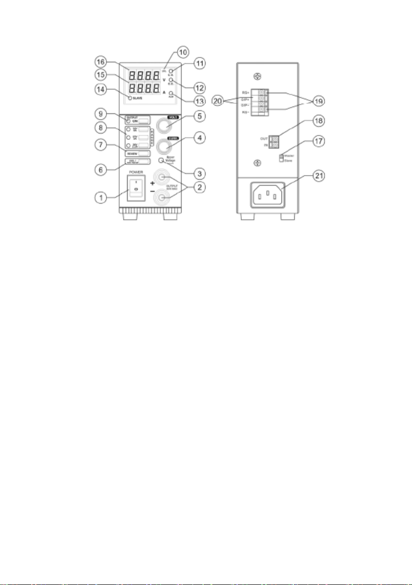
• Make certain that the power supply is set for MASTER operation. To do this, maker
sure the MASTER/SLAVE selector on the rear panel (17) set to MASTER position.
All controls will function as with any a normal power supply.
• With no load connected to the power supply, turn the power supply ON via the
POWER switch on the front panel (1).
• The LED display should light up, however there will not be any reading on the
voltmeter or ammeter.
• Press the OUTPUT ON button (9), its green LED will light up and the voltmeter will
display the set output voltage.
• Take note of the preset RANGE (8) by which LED is illuminated. Adjust the VOLT
control (5) and note the effect on displayed voltage on the LED display.
Selection of Voltage and Current Range
• The three buttons in the RANGE panel (8) will determine the voltage and current
range available from the supply. Depress the corresponding button to place the
power supply in the desired range.
• The appropriate LED will illuminate to show which range the supply is in.
Note: To protect the connected load, the OUTPUT (9) will return to OFF status any time
the output RANGE (8) is changed. The Volt and Amp display will return to zero.
Viewing Settings
• The REVIEW button (7) allows you to check voltage and current limiting settings of
the power supply while the OUTPUT (9) is turned off, or when no load is connected.
This is especially helpful since conventional power supplies require the connection
of some type of load to view the current limit setting.
• To operate, press and hold the REVIEW button (7) to display voltage and current
limiting values.
Note: This is a momentary push button and will only display the settings while held
depressed.
Setting the Current Limiting Value
• Press and hold the PREVIEW button (7).
• Turn the current adjustment (5) to your desired current limit value.
Viewing the Upper Voltage Limit (UVL)
Press UVL/VOLTAGE button (6) to display the default value of Upper Voltage Limit.
The UVL LED (10) will light up during this operation.
Setting the Upper Voltage Limit (UVL) value
• This limited access setting utilizes a recessed screwdriver adjustment on the
front panel (3). Note this is a delicate control and care should be exercised when
adjustment is made.
• While pressing the UVL button (6), insert the small screw driver into (3), slowly turn
clockwise to increase and counter–clockwise to decrease the UVL value.
Note: that only one UVL value can be set for all three ranges. When the output voltage
exceeds the set UVL, the output terminal will automatically turn off and the ALM LED
(13) will illuminate.

5
MASTER & SLAVE OPERATION
• Two or more Tenma 72-8355 Power Supplies can be connected in parallel to
increase output current to the sum of each supply. In this mode, the designated
MASTER supply will control voltage and current settings of the SLAVE supplies.
Preparation and connecting the Control Terminals (18)
• Ensure that all power supplies are set to the same UVL (6) and voltage RANGE (8).
• Set the voltage and current limit of all SLAVE units to maximum values.
• Switch off all power supplies before connection.
• Make certain the MASTER supply has switch (17) set in the MASTER position.
• Set the switch (17) to SLAVE position of all the SLAVE supplies.
• Refer to Fig 8.1 and 8.2 for rear connections of the OUT/IN terminals (18) of the
MASTER and SLAVE units.
• Take note that the connection begins at the OUT of the MASTER and feeds the IN
of the rst SLAVE unit. If additional SLAVE units are used, connect the OUT of the
rst SLAVE, to the IN of the second SLAVE. Then connect the OUT of the second
SLAVE to the IN of the third SLAVE and so on.
Output terminal connection and operation
• You can either use the front OUTPUT terminals (2) or rear O/P+ and O/P– terminals
(20) to connect to the load as shown in Fig 8.3 depending on your application and
requirements.
• For proper performance, all power cables should be of the same thickness and
length.
• Switch on the MASTER unit rst and set to desired voltage, then switch on the
SLAVE units.
• The SLAVE indicator LED (14) should light up in the SLAVE units as a conrmation
of proper connection.
• All output voltage and current of the SLAVE units are now controlled by the
MASTER.
Important Note: If the load connected to the MASTER/SLAVE paralleled supplies falls
to zero amperes, the output voltage will no longer be controlled by the MASTER unit.
Make sure to keep a minimum amount of current draw on the supplies that is at least
several percent of the rated current. This can be accomplished by supplying a small
removable load such as a resistor.

6
SPECIFICATIONS
Input Voltage 90 ~ 264Vac
No load Input Current at 230VAC ≤0.1A
Full Load Input Current at 230Vac ≤0.5A
AC Input Frequency 47Hz ~ 63Hz
Efciency ≥75%
Power Factor ≥0.9
Constant Voltage and Current
Range Selection:
0-16V / 5A selection I 0~16.4V / 0~5.1A
0-27V / 3A selection II 0~27.6V / 0~3.1A
0-36V / 2.2A selection III 0~36.8V / 0~2.3A
Constant Voltage Characteristics :
Load Regulation (0~100%) ≤20mV
Line Regulation (±10%) ≤4mV
Ripple & Noise (p-p) ≤30mV
Constant Current Characteristics : Load Regulation (0~100%) ≤10mA
Line Regulation (±10%) ≤10mA
Meter Accuracy : Voltmeter Accuracy ±1% +2 counts
Ammeter Accuracy ±1% +2 counts
Protection
Adjustable Upper Voltage Limit,
Current Limiting Protection,
Short Circuit, Overload,
Over Temperature Protection
Cooling Natural Convection
Dimensions in mm (WxHxD) 127 x 52 x 335mm / 5” (H) x 2” (W) x 13” (D).
Weight in Kg 1.9Kgs / 4.2Lbs
Remote Sensing Operation
• In situations where the load current is very high, or when there is a long distance of
cable between the output of the supply and the load, a voltage drop can occur. This
can create problems in applications where precise voltage levels are critical. For
this situation, RS+ / RS– terminals (19) are provided on the rear panel for remote
sense connection.
Connection and operation
• Ensure that the front panel OUTPUT selector (9) is OFF.
• Connect the load to either the front OUTPUT (2) or rear O/P alternative output (19)
connections.
• Using separate leads, connect the RS terminals (19) to the load as well, be careful
not to reverse polarity.
• If desired, utilize the REVIEW (7) function to verify proper voltage and current
settings.
• Switch the OUTPUT selector (9) ON.
Note: Be extremely careful not to reverse the polarity between the main output and
remote sensing terminals. Do not leave the load connected to the remote sensing
terminals when not connected to the supply output. If the load must be disconnected
while the supply is on, remove the remote sensing connections rst.

7
MAINTENANCE
Cleaning
• Use a damp cloth and a small amount of liquid detergent if necessary.
• Never submerse the power supply in liquid or allow any liquid to enter the case.
• Do not use any chemicals, abrasives or solvents that could damage the power
supply casing.
Changing the fuse
• Replace the fuse only with one of exactly the same type and rating.
• Disconnect the mains power and unplug the mains lead before replacing the fuse.

8
INFORMATION ON WASTE DISPOSAL FOR CONSUMERS OF ELECTRICAL &
ELECTRONIC EQUIPMENT.
When this product has reached the end of its life it must be treated as Waste
Electrical & Electronic Equipment (WEEE). Any WEEE marked products must not be
mixed with general household waste, but kept separate for the treatment, recovery
and recycling of the materials used. Contact your local authority for details of recycling
schemes in your area. Made in China. PR2 9PP
Man Rev 1.0
Table of contents
Other Tenma Power Supply manuals

Tenma
Tenma 72-8795 User manual

Tenma
Tenma 72-630 User manual

Tenma
Tenma 72-8340 User manual

Tenma
Tenma 72-8690 Series User manual

Tenma
Tenma 72-13300 User manual

Tenma
Tenma 72-7655 User manual

Tenma
Tenma TENMA 72-10495 User manual

Tenma
Tenma 72-2660 User manual

Tenma
Tenma 72-13095 User manual

Tenma
Tenma 72-2685 User manual

Tenma
Tenma 72-8340A User manual

Tenma
Tenma 72-8695A User manual

Tenma
Tenma 72-8345A User manual

Tenma
Tenma 72-7675 User manual

Tenma
Tenma 72-8000 Series User manual

Tenma
Tenma 72-2535 User manual

Tenma
Tenma 72-2630 User manual

Tenma
Tenma 72-6851 User manual

Tenma
Tenma 72-6854 User manual

Tenma
Tenma TENMA 72-10495 User manual