FES Auto OBD-II Assembly instructions

Right Angle OBD-II Connectors
Installation and Set-Up Guide
325 Sharon Park Blvd. #652
Menlo Park, CA 94025
(650) 241-1161
www.fes-auto.com

Auto Sportplus –Installation and Set-Up Guide Page 2
Chapter 1 Dislcaimer .................................................................... 3
Chapter 2 Welcome! ..................................................................... 4
2.1 Features ................................................................................ 4
2.2 What’s in the Box .................................................................... 4
2.3 Required Tools ........................................................................ 4
Chapter 3 Assembly...................................................................... 5
3.1 OBD-II Pin Specifications.......................................................... 5
3.2 Connector Pin Assignment ........................................................ 5
3.3 Assembly ............................................................................... 6
3.3 Dimensions ............................................................................ 6
4 Contact Information ................................................................... 6

Auto Sportplus –Installation and Set-Up Guide Page 3
CHAPTER 1 DISLCAIMER
USE AT YOUR OWN RISK - USE OF THE PRODUCT MIGHT NOT BE ALLOWED ON PUBLIC STREETS.
IT’S THE USER’S RESPONSIBILITY TO USE THE PRODUCT IN ACCORDANCE WITH THE LOCAL
LAWS AND RESTRICTIONS.
Do not use this product until you have carefully read the following agreement. This sets forth the
terms and conditions for the use of this product.
The installation of this product indicates that the buyer has read and understands this
agreement and accepts the terms and conditions.
DISCLAIMER OF LIABILITY
FES, LLC (hereafter SELLER) shall in no way be responsible for the product’s proper use and
service. THE BUYER HEREBY WAIVES ALL LIABILITY CLAIMS.
The BUYER acknowledges that he/she is not relying on the SELLER’s skill or judgment to select or
furnish goods suitable for any particular purpose and that there are no liabilities which extend
beyond the description on the face hereof and the BUYER hereby waives all remedies or liabilities,
expressed or implied, arising by law or otherwise, (including without any obligations of the SELLER
with respect to fitness, merchantability, and consequential damages) or whether or not occasioned
by the SELLER’s negligence.
The SELLER disclaims any warranty and expressly disclaims any liability for personal injury or
damages. The BUYER acknowledges and agrees that the disclaimer of any liability for person injury
is a material term for this agreement and the BUYER agrees to indemnify the SELLER and to hold
the SELLER harmless from any claim related to the item of the equipment purchased. Under no
circumstances will the SELLER be liable for damages or expenses by reason of use or sale of any
such equipment.
The SELLER assumes no liability regarding the improper installation or misapplication of its
products. It is the installer’s responsibility to check for proper installation and if in doubt, contact
the manufacturer.
LIMITATION OF WARRANTY
FES, LLC (hereafter “SELLER”) gives Limited Warranty as to description, quality, merchantability,
fitness for any product’s purpose, productiveness, or any other matter of SELLER’s product sold
herewith. The SELLER shall be in no way responsible for the product’s open use and service and the
BUYER hereby waives all rights other than those expressly written herein. This Warranty shall not
be extended or varied except by written instrument signed by SELLER and BUYER.
The Warranty is Limited to one (1) year from the date of sale and limited solely to the parts
contained in within the product’s kit. All products that are in question of Warranty must be
returned shipping prepaid to the SELLER and must be accompanied by a dated proof of purchase
receipt. All Warranty claims are subject to approval by FES, LLC.
Under no circumstances shall the SELLER be liable for any labor charged or travel time incurred in
diagnosis for defects, removal or reinstallation of this product, or any other contingent expenses.
If the BUYER sends back a failed unit that is out of warranty and chooses to buy a refurbished unit,
the refurbished unit will only carry a 60 day warranty. If the BUYER purchases a new unit at a
predetermined discounted rate, it will have the standard 1 year warranty.
Under no circumstances will the SELLER be liable for any damage or expenses insured by reason of
the use or sale of any such equipment.
IN THE EVENT THAT THE BUYER DOES NOT AGREE WITH THIS AGREEMENT: THE BUYER
MAY PROMPTLY RETURN THIS PRODUCT, IN A NEW AND UNUSED CONDITION, WITH A
DATED PROOF OF PURCHASE, TO THE PLACE OF PURCHASE FOR A FULL REFUND.
THE INSTALLATION OF THIS PRODUCT INDICATES THAT THE BUYER HAS READ AND
UNDERSTANDS THIS AGREEMENT AND ACCEPTS ITS TERMS AND CONDITION

Auto Sportplus –Installation and Set-Up Guide Page 4
CHAPTER 2 WELCOME!
The FES right angle OBD-II connector (with or without power button) is
the lowest profile OBD-II connector available. It is intended for the
enthusiast that requires a high quality OBD-II connector who doesn’t want
to pay some of the outrageous prices that others charge.
2.1 FEATURES
-Low Profile. Just 1.3”(33.2 mm) tall.
-Easy to assemble. Just some simple soldering and a little contact
cement.
-Support for BMW/Mini Pin 9 RPM signal.
2.2 WHAT’S IN THE BOX
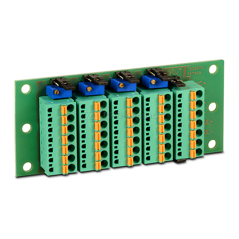
-1 OBD-II base with pins installed.
-1 PCB (optionally with power switch attached).
-1 OBD-II connector top (optionally with power switch button hole).
-1 Piece shrink tubing.
-1 (optional) power switch press on button.
2.3 REQUIRED TOOLS
-Soldering iron and solder
-Heat gun.
-Contact cement.

Auto Sportplus –Installation and Set-Up Guide Page 5
CHAPTER 3 ASSEMBLY
3.1 OBD-II PIN SPECIFICATIONS
The OBD-II specification defines the following pin out:
1. -
2. Bus positive Line of SAE-J1850
3. -
4. Chassis ground
5. Signal ground
6. CAN high (ISO 15765-4 and SAE-J2234)
7. K line of ISO 9141-2 and ISO 14230-4
8. -
9. -
10. Bus negative Line of SAE-J1850
11. -
12. -
13. -
14. CAN low (ISO 15765-4 and SAE-J2234)
15. L line of ISO 9141-2 and ISO 14230-4
16. Battery voltage
Unlabelled pins are left to the vehicle manufacturer and may or may not
be specified. Most cars do not have pins 2 or 10 populated, as the J1850
specification is usually used in large trucks.
3.2 CONNECTOR PIN ASSIGNMENT
Bottom View of Connector

Auto Sportplus –Installation and Set-Up Guide Page 6
3.3 ASSEMBLY
First solder the wires as required to the PCB.
Solder PCB with wires attached to the pins in the connector base.
Use the provided shrink tubing to make a strain relief for the wire (if
one layer isn’t enough to make the wire a snug fit, cut it in half and
double it up.)
Test connections and cable functions to ensure proper electrical
continuity.
Use some contact cement to glue the connector top onto the base.
If required, push the power switch button onto the switch.
3.3 DIMENSIONS
Extended Power Button adds ~0.1”to overall height.
4 CONTACT INFORMATION
Support can be obtained by contacting us via:
Phone: (650) 241-1161
E-Mail: [email protected]
Web: www.fes-auto.com/support
Table of contents
