Festo EGSC-BS-KF Parts list manual

8099637
EGSC-BS-KF
Mini slide
8099637
2018-11c
[8099639]
Instructions | Operat-
ing

Translation of the original instructions
2 Festo — EGSC-BS-KF — 2018-11c

3Festo — EGSC-BS-KF — 2018-11c
1 About this document................................................................................................... 4
2 Safety........................................................................................................................... 4
2.1 Safety instructions........................................................................................................ 4
2.2 Intended use................................................................................................................ 4
2.3 Training of qualified personnel..................................................................................... 4
3 Additional information................................................................................................ 4
4 Service..........................................................................................................................4
5 Product overview......................................................................................................... 5
5.1 Function....................................................................................................................... 5
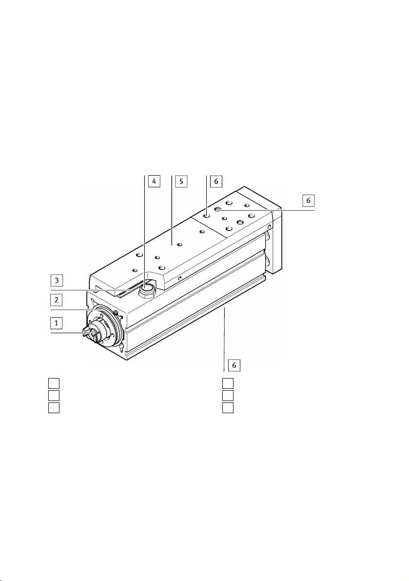
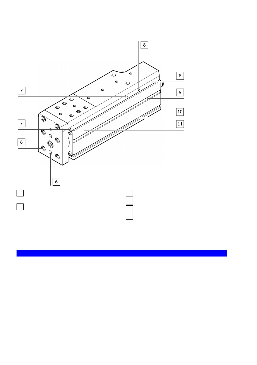
5.2 Design........................................................................................................................... 5
6 Transport..................................................................................................................... 6
7 Assembly..................................................................................................................... 7
7.1 Preparation................................................................................................................... 7
7.2 Mounting...................................................................................................................... 8
7.3 Attachment................................................................................................................... 9
7.4 Mounting accessories................................................................................................... 10
8 Commissioning............................................................................................................ 12
9 Service..........................................................................................................................13
10 Disassembly................................................................................................................ 14
11 Disposal........................................................................................................................14
12 Fault clearance............................................................................................................ 15
13 Technical data............................................................................................................. 16
Table of contents

1 About this document
All available documents for the product èwww.festo.com/pk.
The mini slideEGSC-BS-KF is designated as product in these operating instructions. Read the operat-
ing instructions carefully before starting all work on the product.
2 Safety
2.1 Safety instructions
– Observe product labelling.
– Before working on the product, switch off the power supply and secure it against being switched
back on.
– Store the product in a cool, dry environment that is protected against UV and corrosion. Ensure
short storage times.
– Protect the product during operation from damaging influences.
Damaging influences include grinding dust, glowing chips or sparks.
– Observe tightening torques. Unless otherwise specified, the tolerance is ±20%.
2.2 Intended use
The mini slide is intended to be used for positioning payloads in combination with tools.
The mini slide is approved for the "Slide Operation" mode è Fig.1.
Fig. 1
2.3 Training of qualified personnel
Only skilled personnel may carry out installation, commissioning, maintenance and disassembly of the
product. The qualified personnel must be familiar with installation of electrical control systems.
3 Additional information
Accessories è www.festo.com/catalogue
4 Service
Contact your regional Festo contact person if you have technical questions
è www.festo.com
About this document
Festo — EGSC-BS-KF — 2018-11c4

5 Product overview
5.1 Function
A rotating ball screw drive converts the rotation of a motor into straight-line motion. As a result, the
slide 5 moves backwards and forwards. The slide is ball-bearing guided. The reference position of the
slide can be determined using proximity sensors (è 7.4 Mounting accessories) or by referencing a
fixed stop (retracted end position).
5.2 Design
1Drive hub
2Interface for motor mounting kit
3Guide rail
4Venting hole with filter element
5Slide with ball guide
6Thread/centring holes for attachment com-
ponents
Fig. 2
Product overview
5Festo — EGSC-BS-KF — 2018-11c

6Thread/centring holes for attachment com-
ponents
7Drilled hole for accessories, at both ends
(e.g. clamping unit)
8Thread for optional switch lug
9Slot for sensor bracket
10 Slots for attachment
11 Profile housing
Fig. 3
6 Transport
NOTICE!
Unexpected movement of components. The mini slide is unbraked. Without input torque, the slide is
freely movable.
• Secure slide during transport.
• Take product weight into account è 13 Technical data.
Transport
6 Festo — EGSC-BS-KF — 2018-11c

7 Assembly
7.1 Preparation
– Do not modify the screws and threaded pins.
Exception: if immediate modification is required based on these operating instructions.
– Select the motor and motor mounting kit from the Festo catalogue èwww.festo.com/catalogue
When using other motors: observe the critical limits for forces, torques and speeds
è 13 Technical data.
– When mounting the motor: follow the assembly instructions for the motor mounting kit.
– Connect motor cables only after the mini slide is mounted.
Fig. 4
NOTICE!
The reference position is lost when the motor is dismounted (e.g., when turning the motor around).
• Start homing è 8 Commissioning.
CAUTION!
With vertical or diagonal mounting position:
When power is off, the slide can travel or fall uncontrolled into the lower end position. Injury due to
impacts or crushing.
• Bring moving parts of the product into a safe end position or secure them against falling.
– Place the product in such a way that the operating elements can be reached.
– Install product without tension or distortion.
– Fasten product to a mounting surface with flatness of 0.05% of the stroke length, but max.
0.5mm.
For gantry applications, attention must also be paid to parallel alignment or product height when
aligning the axes.
For additional information, contact your local Festo Service.
Assembly
7Festo — EGSC-BS-KF — 2018-11c

7.2 Mounting
Interfaces for mounting components
On the housing On the profile
With screws For example, with profile mounting EAHF-L2 1)
1) Accessoriesèwww.festo.com/catalogue
Tab. 1 Mounting alternatives
1. Select mounting components according to the hole pattern èwww.festo.com/catalogue
2. Mount the mounting components outside the positioning range to avoid collisions.
3. Mount the mini slide.
4. Tighten screws evenly.
Size 25 32 45 60
Screw
(on housing)
M3 M4 M5 M5
Max. screw-in depth D [mm] 6 8.5 7 8
Tightening torque [Nm] 1.4 3.4 3.2 3.2
Centring H71) [mm] @ 5 @ 7
1) Remove the rubber cover cap
Tab. 2
Assembly
8 Festo — EGSC-BS-KF — 2018-11c

7.3 Attachment
Requirements
NOTICE!
A warped attachment component bends the slide and shortens the service life of the guide.
• Use an attachment component with an even surface. Evenness: t = 0.01 mm è Fig.5
• Mount only to the mounting surface (B) è Fig.7.
Fig. 5
– Set down rated load in such a way that the tilt moment resulting from the force (parallel to the
axis of movement) and lever arm are kept as small as possible.
– Avoid collisions of the mounting part and payload with other mounting parts è Fig.6.
Fig. 6
Assembly
9Festo — EGSC-BS-KF — 2018-11c

Mounting
– Fasten the attachment to the slide with screws and centring sleeves. Observe the maximum screw-
in depth D and tightening torque è Tab.3.
For attachment components with their own guide:
– Precisely adjust the additional guide and mini slide or use a connection that enables a tolerance
compensation. In this way, the guide is not overloaded.
BAssembly surface
Fig. 7
Size 25 32 45 60
Screw M3 M4 M5 M5
Max. screw-in depth D [mm] 4.5 5 6 8
Tightening torque [Nm] 1.5 2.7 5.1 6.5
Centring H7 [mm] @ 2 @ 4 @ 5 @ 7
Tab. 3
7.4 Mounting accessories
To protect the end positions against uncontrolled overtravel:
– Check the necessity of proximity sensors (hardware limit switches).
If proximity sensors are used as limit switches:
– Preferably use proximity sensors with normally closed function.
This protects against excess travel beyond the end position, if the proximity sensor cable is
broken.
If proximity sensors are used as reference switches:
– Use proximity sensors that correspond to the input of the controller being used.
Assembly
10 Festo — EGSC-BS-KF — 2018-11c
Other manuals for EGSC-BS-KF
1
Table of contents


