Festo PDAD Series User manual

(en) Operating
instructions
8068814
1701g
[8068816]
Adsorption dryer
PDAD

2 | Festo PDAD 1701g
Original instructions
Installation and commissioning are to be
carried out only by qualified personnel in
accordance with the operating instructions.

Festo PDAD 1701g English | 3
Table of contents
1. Introduction .................................................................................................................. 4
2. Safety............................................................................................................................ 5
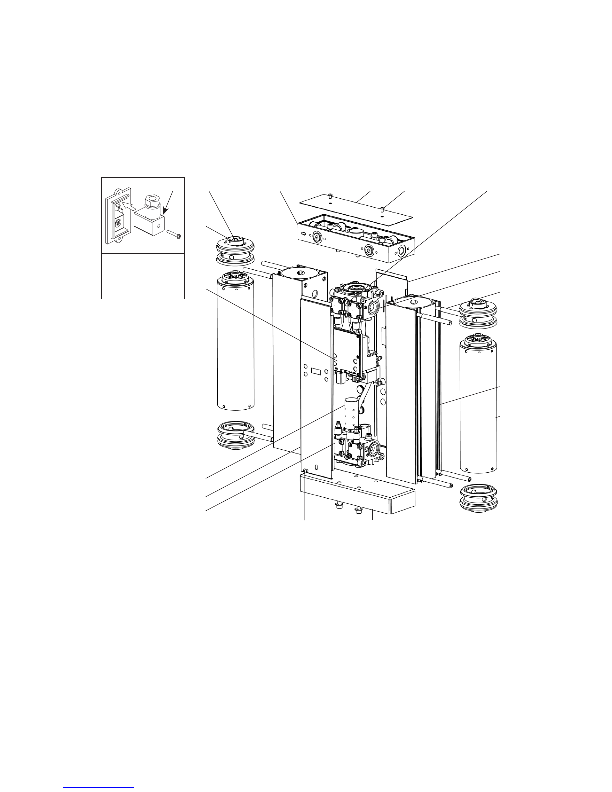
3. Component designation................................................................................................ 7
3.1 Overview....................................................................................................................... 7
3.2 Electronic controller 2................................................................................................ 9
3.3 Multiple distributor aJ ................................................................................................ 9
3.4 Desiccant cartridge with integrated dust filter 9........................................................ 9
3.5 Reservoir 7................................................................................................................. 9
4. Function ...................................................................................................................... 10
5. Installation.................................................................................................................. 11
5.1 Mounting the micro filter on the dryer ........................................................................ 11
5.2 Pneumatic connection................................................................................................. 13
5.3 Assembling the mounting accessories on the dryer.................................................... 14
5.4 Changing the connections for the inlet and outlet ...................................................... 15
5.5 Installation conditions ................................................................................................ 16
6. Power supply .............................................................................................................. 17
6.1 Voltage connection ..................................................................................................... 17
6.2 Power supply socket connection................................................................................. 18
6.3 Alarm connection ........................................................................................................ 19
7. Commissioning ........................................................................................................... 20
8. Maintenance and care................................................................................................. 22
8.1 LED displays................................................................................................................ 22
8.2 Decommissioning for maintenance purposes ............................................................. 24
8.3 Maintenance and service ............................................................................................ 24
8.4 Removing/installing the front or rear cover ................................................................ 25
8.5 Replacing or cleaning the air nozzle............................................................................ 26
8.6 Cleaning the silencer................................................................................................... 27
8.7 Resetting the controller .............................................................................................. 28
9. Troubleshooting.......................................................................................................... 29
9.1 General fault finding ................................................................................................... 29
9.2 Electrical troubleshooting ........................................................................................... 30
10. Accessories................................................................................................................. 31
11. Technical data............................................................................................................. 32

4 | Festo PDAD 1701g English
1. Introduction
For all available product documentation www.festo.com/pk
The product described in these operating instructions may only be installed, operated and
maintained if these operating instructions have been completely read and understood by
the employees handling the product.
These operating instructions and in particular the safety instructions are to be kept with
the product or as a print-out or copy. The operating instructions must be strictly adhered
to.
Please keep the following information available if you need to contact Festo with regard to
the product or the operating instructions.
• Part number and type designation
• Date commissioned
The part number and type designation can be found on the rating plate on the top right-
hand side of the device. Please note this information in the operating instructions as a
reminder and for future use.
The dryer is delivered in protective packaging. Use due diligence when transporting,
loading and unloading the device.
On delivery, the dryer is configured with an air nozzle for an operating pressure of 7 to 9
bar. You must ensure that the correct air nozzle is attached for the anticipated operating
pressure. For more information see the table with technical data in chapter 11.
Scope of delivery
Adsorption dryer PDAD
Micro filter
MS6-LFM
Adapter kit Power supply
socket
Tubing Operating
instructions PDAD

Festo PDAD 1701g English | 5
2. Safety
Festo expressly excludes any liability or responsibility for damages and/or injuries which
result from violation of these operating instructions.
The device may only be used for its intended purpose. The cold regenerative adsorption
dryer is only to be used according to its intended purpose for drying pressurised air under
the conditions described in chapter 11 of these operating instructions. Any other use of
the device is considered not for its intended purpose. Festo is not liable for damages which
result from misuse.
The following symbols indicate a possible hazard. Where such hazards arise, the
appropriate measures must be taken in order to reduce the risk for the user or operator of
the product.
Caution:
Source of danger
Attention:
Danger due to
electrical voltage
Attention:
Danger due to high
pressures
Note on Pressure Equipment Directive
Classification of the dryers in pressure equipment categories
Category
Type
I
PDAD-09
I
PDAD-13
I
PDAD-22
I
PDAD-51
II
PDAD-73
II
PDAD-100
Notes on commissioning and maintenance
Vibrations can cause fatigue in the material and can decrease the endurance limit of the
adsorption dryers and mounting components.
• Protect adsorption dryers and mounting components against mechanical vibrations.
Commissioning and the intervals for periodic inspections are subject to the applicable
national regulations.
When carrying out maintenance work, inspect components visually for damage. Replace
the device if necessary.

6 | Festo PDAD 1701g English
The following safety regulations need to be strictly adhered to:
• These operating instructions or a print-out or copy thereof are to be left at the place
where the product is installed.
• Repair work on the device is only to be carried out by personnel authorised by Festo.
• Operating, repair and maintenance personnel must be aware of the following
information:
– Accident prevention regulations
– Safety information (general and device specific)
– Device safety equipment
– Measures to be taken in an emergency
• It is the installer's responsibility to ensure that the cables to and from the dryer are
suitable for the task, correspond to the applicable laws and have been subjected to a
visual check and tests before commissioning. All cables must be fitted in an appropriate
manner.
• The device must be decommissioned before carrying out any maintenance or repair
work. Operators and other personnel are exposed to a risk if work is carried out on a
running device. Decommissioning the device means disconnecting it from the power
supply and compressed air supply, and ensuring the pressure is completely reduced.
• Only trained specialists who are aware of the electrical requirements of the device
as described in these operating instructions as well as the safety regulations and
conditions are permitted to carry out work on the electrical components and the power
supply of the device.
• Use suitable, correctly sized tools that are in good condition to carry out any work on
the device.
• Only use accessories and spare parts from the manufacturer. There is no guarantee that
non-original spare parts are designed and manufactured to correspond to the safety
and operating requirements of the device. Festo takes no liability for device faults which
result from the use of unapproved spare parts.
• Use suitable and safe work platforms or other secure work access options to carry out
installation work above head height.
• Do not make any design changes to the product. Changes and modifications may only
be carried out by Festo.
• All faults or defects which could impair safety must be eliminated before using the
device.
• Used objects and materials must be correctly disposed of in line with the local laws and
conditions. This applies in particular to the desiccant cartridges.

Festo PDAD 1701g English | 7
3. Component designation
On the back of
the dryer
ad
1Upper valve block
2Electronic controller
3Lower valve block
4Floor plate
5Front cover
6Mounting screw front cover
7Reservoir
8Mounting screw reservoir
9Desiccant cartridge with integrated
dust filter
aJ Multiple distributor
aA Cover plate
aB Cover plate mounting screw
aC Rear cover
aD Power supply socket
aE Reservoir seal screw
aF Seal
aG Silencer
aH Air nozzle
aB aHaJ aA
1
aC
8
7
9
3
aG
5
6
2
aF
4
aE
3.1 Overview
The figure below shows the main components of the dryer
PDAD-09/13/22/51/73.

8 | Festo PDAD 1701g English
On the
inside of the
dryer
ad
1Upper valve block
2Electronic controller
3Lower valve block
4Floor plate
5Front cover
6Mounting screw front cover
7Reservoir
8Mounting screw reservoir
9Desiccant cartridge with integrated
dust filter
aJ Multiple distributor
aA Cover plate
aB Cover plate mounting screw
aC Rear cover with cable throughfeed for
mains connection
aD Power supply socket
aE Reservoir seal screw
aF Seal
aG Silencer
aH Air nozzle
aI Multiple distributor connection
screws
bJ Seal for connecting multiple
distributor
The figure below shows the main components of the dryer
PDAD-100.
aB aH
aJ
aA
aI
1
aC
8
7
9
3
5
6
4
2
aG
aF
aE bJ

Festo PDAD 1701g English | 9
3.2 Electronic controller 2
The valve blocks (on top and below) are actuated by solenoid valves in the controller which
determine the pressure and direction of the air flow in the desiccant cartridge.
3.3 Multiple distributor aJ
The standard design of the dryer is configured in such a way that the inlet openings are
on the left and the outlet openings on the right when looking at the front of the device. By
using the opening nozzles several different opening requirements become available. See
also section 5.4.
Inlet
See the direction of the arrows
for inlet side of the dryer
Outlet
Installation in corners
3.4 Desiccant cartridge with integrated dust filter 9
The desiccant cartridges contain a drying agent which has been developed for drying
compressed air. The drying agent is contained in a transparent tube with end pieces which
allow the air to flow through at both ends. In the upper part of each cartridge is a 1 micron
filter to separate residual dust from the drying agent. The cartridge length varies with the
rated output of the dryer.
3.5 Reservoir 7
The desiccant cartridge is located in an extruded aluminium reservoir and has pressurised
end caps. The operating pressure and the flow through the individual cartridges is
controlled by the valve blocks positioned between the two reservoirs. The regenerative
air flow (purge air flow) is controlled by an external air nozzle with a small opening (front,
central) on the upper valve block, accessible by removing the cover.

10 | Festo PDAD 1701g English
4. Function
During dry operation an even, uninterrupted supply of compressed air should be provided
according to the specification.
This function is achieved with two compressed air reservoirs which operate in alternating
cycles. If air is being dried in one reservoir, the drying agent in the second reservoir can
regenerate.
In the adsorption dryer the main air flow is fed through the desiccant cartridge(s) of a
reservoir. This removes the moisture so the required pressure dew point can be achieved.
A small amount of the dry air (purge air) is fed to the other reservoir. The purge air flows
through the desiccant cartridge(s), escapes into the atmosphere through a drain valve and
thus regenerates the drying agent.
The regeneration cycle lasts 120 seconds. The corresponding drain valve is then closed.
This means the regenerated reservoir can be brought up to system pressure with the purge
air and can switch to the operating cycle. After a further 50 seconds the other reservoir
starts a new regenerative operating cycle.

Festo PDAD 1701g English | 11
In order to protect the drying agent from
contaminated pressurised air the micro
filter MS6-LFM supplied must be mounted
on the inlet of the dryer. On delivery, the
three inlet options are on the left-hand side
of the dryer (see arrow). If an inlet on the
right-hand side is required the multiple
distributor in the cover of the dryer must be
turned (see chapter 5.4).
1. Select an inlet opening.
Remove any sealing plugs and attach
them to the unused inlet.
2. Insert a lightly greased O-ring 2 in
the slot of inlet 1.
3. Fit the module connecting plate 3
with hollow bolt 4with spanner size
10 (for PDAD-...y) or max. 14 Nm (for
PDAD-...½). The maximum tightening
torque is 15 Nm (for PDAD-...y) or
max 18 Nm (for PDAD-...½).
The module connecting plate 3can
be adjusted 90° for horizontal instal-
lation of the dryer.
5. Installation
5.1 Mounting the micro filter on the dryer
1
2
3
3
4

12 | Festo PDAD 1701g English
4. Insert flat seal 5in the slot of the
module connecting plate 3and
O-ring 6in the slot of micro filter
MS 6-LFM.
5. Position micro filter MS6-LFM on the
dryer.
Observe the direction of flow from 1
to 2. The number 7on the product
housing serves as a guide.
6. Place module connector 8between
the micro filter MS6-LFM and the
dryer and then fit it using two screws.
The prominent edge of the modu-
le connector should be pointing
upwards. The tightening torque of the
screws is 1.2 Nm ±10%.
7. Connect the supplied 4 mm tubing 9
(outside diameter) to the condensate
drain of the micro filter. Connect the
other end of the tubing with the screw
QSL-F on the back of the dryer (upper
connection 'condensate inlet').
8. Connect the tubing with 4 mm diame-
ter (outside diameter) to screw QSL-F
on the back of the dryer (lower con-
nection 'condensate outlet'). Connect
the other end of the tubing with suita-
ble condensate collecting bowls.
8
9
5
3
6
7

Festo PDAD 1701g English | 13
1
Note
The micro filter MS6-LFM must be placed vertically (±5°) regardless of the installation
location of the dryer. Check that there is sufficient space below the filter bowl (min.
100 mm). When installing horizontally, support with suitable material.
5.2 Pneumatic connection
1. Turn the connection screw or piping into the threaded connection of the micro filter
MS6-LFM.
Note the screw-in depth of the threaded connection:
2. Turn the connection screw or pipeline
into the outlet of the dryer.
Adapter assembly (only for
PDAD-...-N...):
Turn the NPT adapter supplied 1
with sealing ring into the outlet of the
dryer. The maximum tightening torque
is 15 Nm (for PDAD-...N3/8) or max
18 Nm (for PDAD-...½).
Type
Max. screw-in depth [mm]
ISO 228
MS6(N)-LFM 12.0
(NPT)
10.3

14 | Festo PDAD 1701g English
Note
It is recommended that you install a by-pass line around the dryer and the prefilter.
Note
The mounting accessories are not in the scope of the delivery of the adsorption dryer
PDAD. These parts must be ordered separately.
O B
C D
Wall mounting ABMW-PDAD Foot mounting ABMF-PDAD
The maximum tightening torque is 10 Nm.
Note:
It is not possible to mount the micro filter
MS6-LFM on the inlet on the back of the
dryer.
The maximum tightening torque is 10 Nm.
5.3 Assembling the mounting accessories on the dryer

Festo PDAD 1701g English | 15
5.4 Changing the connections for the inlet and outlet
1. Delivery state: three inlet options on the
left-hand side of the dryer (viewed from the
front).
5. Dryer after removing the multiple
distributor.
Inlet
Outlet
2. Loosen both mounting screws (PZ 2) from
the cover and remove the cover.
6. Turn the multiple distributor 180°
and reinstall it with the help of the four
mounting screws (max. tightening torque
20 Nm). Make sure both O-rings are
properly seated.
3. Dryer after removing the cover 4. Release the four mounting screws of the
multiple distributor (SW 5) and remove the
multiple distributor.
7. Reinstall the cover using both mounting
screws (max. tightening torque 1 Nm).
8. Location of the connections for the inlet
and outlet after carrying out the steps
described.
Inlet
Outlet

16 | Festo PDAD 1701g English
5.5 Installation conditions
Correct Incorrect Correct Incorrect
The dryer is designed for safe operation under the following conditions:
• Use indoors
• Height of up to 2,000 m
• Maximum relative air humidity 80% for temperatures up to 31 °C declining in a linear
fashion to 50% at 40 °C

Festo PDAD 1701g English | 17
6. Power supply
6.1 Voltage connection
1. The dryer can be operated with alternating current (AC) or direct current (DC).
Make sure that only one power source is connected to the correct socket. The cover
supplied must then be attached to the unoccupied power supply, see chapter 6.2.
Apower source connected to the wrong power supply can destroy the electronics!
2. The power supply is provided using the power connection socket supplied.
Voltage Current intensity
12 V DC
24 V DC
100 V AC
115 V AC
230 V AC
240 V AC
0.8 A
0.4 A
0.16 A
0.14 A
0.07 A
0.067 A
3. The dryer is isolated for protection
and therefore does not require
earthing.
4. A suitable external fuse must be
used.
5. The cable used must correspond to
the local installation conditions as
well as the power consumption.
Seal
1 (+)
Phase
2 (–)
Earthed conductor

18 | Festo PDAD 1701g English
6.2 Power supply socket connection
Voltage: 100 to 240 V AC
Cover
Voltage: 12 to 24 V AC
Cover
Note
The connections for the network socket on the PDAD-100 are on the bottom behind the
cover. These can be removed after unfastening the mounting screw (SW 5), see chapter 8.4.

Festo PDAD 1701g English | 19
6.3 Alarm connection
The electronic controller has an alarm relay with DIN connection. A visual or acoustic
remote alarm system can be connected outside the dryer with this DIN connection.
In the event of a fault or when servicing is required the alarm relay switches. At the same
time, red LEDs on the display panel show the fault which has occurred, see chapter 8.1.
When the fault is eliminated, the alarm relay resets, but only after the current switching
cycle has finished or the control device has been reset after a cartridge change.
In order to set up the remote alarm system a suitable cable must be fed through a rubber
grommet in the rear wall for electronic control.
1. Connect the switching pin of an alarm installation with the external power supply to
pins 1 and 2 of the DIN plug.
2. Remove the cover from the DIN connection marked 'Alarm' as described in number
1 while the power supply to the dryer is interrupted and connect the wired DIN con-
nection.
Make sure that the seal and screw are inserted correctly.
– Socket MSSD-E (Festo
part no. 14098)
– Hirschmann GDS 207
Alarm relay current intensity Plug for DIN connection
Max. 3 A, 28 V DC
External power supply

20 | Festo PDAD 1701g English
On delivery, the adsorption dryer is configured with an air nozzle for an
operating pressure of 7 to 9 bar. The air nozzle must be changed for other
operating pressures. The set with the remaining air nozzles is not part of
the scope of delivery and must be ordered separately, see Accessories
(chapter 10, see also www.festo.com/sp). Each air nozzle is engraved
with a number for identification purposes.
1. Determine the suitable air nozzle for the anticipated operating
pressure using the table with technical data in chapter 11.
2. If necessary, replace the air nozzle in the dryer. To do this, follow
the steps in chapter 8.4 and chapter 8.5
1. Close valves A, B, C and D.
2. Switch on the compressor.
3. Slowly open valve A.
Compressed air flows through the
desiccant cartridge and escapes
into the atmosphere via the silen-
cer.
4. Check the dryer for leaks.
C D
O B
7. Commissioning
Other manuals for PDAD Series
1
This manual suits for next models
6
Table of contents
Other Festo Dryer manuals