Festo PDAD User manual

PDAD
Adsorption dryer
Operating instruc-
tions
8167686
2022-02i
[8167688]

Translation of the original instructions
Hirschmann® is a registered trademark of its respective trademark holder in certain countries.

Festo — PDAD — 2022-02i
3
Table of contents
1 About this document. . . . . . . . . . . . . . . . . . . . . . . . . . . . . . . . . . . . . . . . . . . . . . . . . . . . . . . . . . . . . 5
1.1 Applicable documents. . . . . . . . . . . . . . . . . . . . . . . . . . . . . . . . . . . . . . . . . . . . . . . . . . . . . . . 5
1.2 Product labelling. . . . . . . . . . . . . . . . . . . . . . . . . . . . . . . . . . . . . . . . . . . . . . . . . . . . . . . . . . . 5
2Safety. . . . . . . . . . . . . . . . . . . . . . . . . . . . . . . . . . . . . . . . . . . . . . . . . . . . . . . . . . . . . . . . . . . . . . . . . . 6
2.1 Safety instructions. . . . . . . . . . . . . . . . . . . . . . . . . . . . . . . . . . . . . . . . . . . . . . . . . . . . . . . . . . 6
2.2 Intended use. . . . . . . . . . . . . . . . . . . . . . . . . . . . . . . . . . . . . . . . . . . . . . . . . . . . . . . . . . . . . . 7
2.3 Training of qualified personnel. . . . . . . . . . . . . . . . . . . . . . . . . . . . . . . . . . . . . . . . . . . . . . . . 7
3 Additional information. . . . . . . . . . . . . . . . . . . . . . . . . . . . . . . . . . . . . . . . . . . . . . . . . . . . . . . . . . . . 7
4 Product overview. . . . . . . . . . . . . . . . . . . . . . . . . . . . . . . . . . . . . . . . . . . . . . . . . . . . . . . . . . . . . . . . 8
4.1 Product Range Overview. . . . . . . . . . . . . . . . . . . . . . . . . . . . . . . . . . . . . . . . . . . . . . . . . . . . . 8
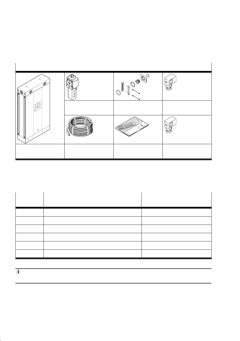
4.1.1 Scope of delivery. . . . . . . . . . . . . . . . . . . . . . . . . . . . . . . . . . . . . . . . . . . . . . . . . . . 8
4.1.2 Not in scope of delivery. . . . . . . . . . . . . . . . . . . . . . . . . . . . . . . . . . . . . . . . . . . . . 8
4.2 Function. . . . . . . . . . . . . . . . . . . . . . . . . . . . . . . . . . . . . . . . . . . . . . . . . . . . . . . . . . . . . . . . . . 9
4.2.1 Functional principle. . . . . . . . . . . . . . . . . . . . . . . . . . . . . . . . . . . . . . . . . . . . . . . . . 9
4.3 Structure. . . . . . . . . . . . . . . . . . . . . . . . . . . . . . . . . . . . . . . . . . . . . . . . . . . . . . . . . . . . . . . . . 10
4.3.1 Main components PDAD-09/-13/-22/-51/-73. . . . . . . . . . . . . . . . . . . . . . . . . . 10
4.3.2 Main components PDAD-100. . . . . . . . . . . . . . . . . . . . . . . . . . . . . . . . . . . . . . . . 11
4.3.3 Electronic controller. . . . . . . . . . . . . . . . . . . . . . . . . . . . . . . . . . . . . . . . . . . . . . . 12
4.3.4 Multi-way distributors. . . . . . . . . . . . . . . . . . . . . . . . . . . . . . . . . . . . . . . . . . . . . 12
4.3.5 Drying agent cartridge with integrated dust filter. . . . . . . . . . . . . . . . . . . . . . . 12
4.3.6 Air reservoir. . . . . . . . . . . . . . . . . . . . . . . . . . . . . . . . . . . . . . . . . . . . . . . . . . . . . . 12
4.3.7 Alarm relay. . . . . . . . . . . . . . . . . . . . . . . . . . . . . . . . . . . . . . . . . . . . . . . . . . . . . . . 12
4.3.8 Air gun nozzles. . . . . . . . . . . . . . . . . . . . . . . . . . . . . . . . . . . . . . . . . . . . . . . . . . . 12
4.3.9 Display components. . . . . . . . . . . . . . . . . . . . . . . . . . . . . . . . . . . . . . . . . . . . . . . 13
5Assembly. . . . . . . . . . . . . . . . . . . . . . . . . . . . . . . . . . . . . . . . . . . . . . . . . . . . . . . . . . . . . . . . . . . . . . 14
5.1 Ports for input and output. . . . . . . . . . . . . . . . . . . . . . . . . . . . . . . . . . . . . . . . . . . . . . . . . . 14
5.2 Assembly. . . . . . . . . . . . . . . . . . . . . . . . . . . . . . . . . . . . . . . . . . . . . . . . . . . . . . . . . . . . . . . . 17
5.2.1 Mount micro filter. . . . . . . . . . . . . . . . . . . . . . . . . . . . . . . . . . . . . . . . . . . . . . . . . 17
5.2.2 Condensate input and condensate output. . . . . . . . . . . . . . . . . . . . . . . . . . . . . 19
5.3 Installing mounting accessories. . . . . . . . . . . . . . . . . . . . . . . . . . . . . . . . . . . . . . . . . . . . . . 20
6 Installation. . . . . . . . . . . . . . . . . . . . . . . . . . . . . . . . . . . . . . . . . . . . . . . . . . . . . . . . . . . . . . . . . . . . 21
6.1 Pneumatic installation. . . . . . . . . . . . . . . . . . . . . . . . . . . . . . . . . . . . . . . . . . . . . . . . . . . . . 21
6.2 Power supply connection. . . . . . . . . . . . . . . . . . . . . . . . . . . . . . . . . . . . . . . . . . . . . . . . . . . 21
6.3 Connection ALARM. . . . . . . . . . . . . . . . . . . . . . . . . . . . . . . . . . . . . . . . . . . . . . . . . . . . . . . . 24
6.4 EM connection. . . . . . . . . . . . . . . . . . . . . . . . . . . . . . . . . . . . . . . . . . . . . . . . . . . . . . . . . . . . 25
7 Commissioning. . . . . . . . . . . . . . . . . . . . . . . . . . . . . . . . . . . . . . . . . . . . . . . . . . . . . . . . . . . . . . . . . 26
7.1 Setting device for the pressure range. . . . . . . . . . . . . . . . . . . . . . . . . . . . . . . . . . . . . . . . . 26
7.1.1 Commissioning device. . . . . . . . . . . . . . . . . . . . . . . . . . . . . . . . . . . . . . . . . . . . . 26
7.1.2 Resetting the electronic controller. . . . . . . . . . . . . . . . . . . . . . . . . . . . . . . . . . . 27
8 Maintenance. . . . . . . . . . . . . . . . . . . . . . . . . . . . . . . . . . . . . . . . . . . . . . . . . . . . . . . . . . . . . . . . . . . 27
8.1 Maintenance work. . . . . . . . . . . . . . . . . . . . . . . . . . . . . . . . . . . . . . . . . . . . . . . . . . . . . . . . . 27
8.2 Shut down the device. . . . . . . . . . . . . . . . . . . . . . . . . . . . . . . . . . . . . . . . . . . . . . . . . . . . . . 28
8.3 Remove covering and mount. . . . . . . . . . . . . . . . . . . . . . . . . . . . . . . . . . . . . . . . . . . . . . . . 28

4
Festo — PDAD — 2022-02i
8.4 Replacing air gun nozzle. . . . . . . . . . . . . . . . . . . . . . . . . . . . . . . . . . . . . . . . . . . . . . . . . . . . 29
8.5 Cleaning the air gun nozzle. . . . . . . . . . . . . . . . . . . . . . . . . . . . . . . . . . . . . . . . . . . . . . . . . . 31
8.6 Cleaning the silencer. . . . . . . . . . . . . . . . . . . . . . . . . . . . . . . . . . . . . . . . . . . . . . . . . . . . . . . 31
9 Malfunctions. . . . . . . . . . . . . . . . . . . . . . . . . . . . . . . . . . . . . . . . . . . . . . . . . . . . . . . . . . . . . . . . . . . 32
9.1 Diagnostics. . . . . . . . . . . . . . . . . . . . . . . . . . . . . . . . . . . . . . . . . . . . . . . . . . . . . . . . . . . . . . . 32
9.2 Diagnostics via LED. . . . . . . . . . . . . . . . . . . . . . . . . . . . . . . . . . . . . . . . . . . . . . . . . . . . . . . . 34
10 Technical data. . . . . . . . . . . . . . . . . . . . . . . . . . . . . . . . . . . . . . . . . . . . . . . . . . . . . . . . . . . . . . . . . . 34
10.1 Nominal flow rate. . . . . . . . . . . . . . . . . . . . . . . . . . . . . . . . . . . . . . . . . . . . . . . . . . . . . . . . . . 36

Festo — PDAD — 2022-02i
About this document
5
1 About this document
1.1 Applicable documents
All available documents for the product è www.festo.com/sp.
Document Product Contents
Assembly instruc-
tions
Service kit PDAD-…-SP12000 Replacing the drying agent cartridges
Tab. 1: Applicable documents
1.2 Product labelling
•Observe the specifications on the product.
The product labelling is divided into the following 2 parts.
Product labelling part 1
The product labelling part 1 is located on the right side of the device. The product labelling part 1
enables the product to be identified.
Product labelling (example) Meaning
PDAD-09-G3/8 Order code
552170 Part number
YYYY-MM YYYY = year of manufacture, MM=month of manufacture
Pxxxxx xxxxx = internal check number
X-X-XXX-KC-XXX-XXX X = symbol of the KC-Mark Certificate (test mark for Korea)
p max: 16 bar Max. input pressure
Tmax: 50 °C Max. ambient temperature
Tmin: 2 °C Min. ambient temperature
V: 4.2 l XX = pressure equipment volume V in litres
Festo SE & Co. KG Manufacturer
DE-73734 Esslingen Manufacturer’s address
Made in xxxxx xxxxx = country of manufacture
Tab. 2: Product labelling part 1 (example)

6
Festo — PDAD — 2022-02i
Safety
Product labelling part 2
The product labelling part 2 is located on the power connection of the device. The product labelling
part 2 contains information on the power connection of the device.
Power connection Product labelling Meaning
Top power connec-
tion (AC)
100 - 240 V AC Voltage range when operating with alternating current
(AC)
~ 50 - 60 Hz Required mains frequency
0.14 A -110 V AC Current consumption when operating with 110 V AC
0.07 A - 230 V AC Current consumption when operating with 230 V AC
Bottom power con-
nection (DC)
12 - 24 V Voltage range when operating with direct current (DC)
0.4 A - 24 V DC Current consumption when operating with 24 V DC
0.8 A - 12 V DC Current consumption when operating with 12 V DC
IP65 Degree of protection in accordance with EN 60529
Tab. 3: Product labelling part 2
Warning symbol Meaning
Attention! Dangerous voltage
Risk of high pressure
Tab. 4: Warning symbol on product labelling part 2
Warnings on the product (de, en) Meaning
Gefahr
Auf korrekte Netzspannung achten. Nur eine einzige Spannungs-
quelle anschliessen.
Danger
Make sure the mains voltage is
correct. Only connect a single
voltage source.
Danger
Ensure correct power source is connected. Connect only one
source.
Tab. 5: Warnings on the product
2Safety
2.1 Safety instructions
–Only use the product in its original condition without unauthorised modifications.
–Only use the product if it is in perfect technical condition.
–Observe the identifications on the product.
–Take into account the ambient conditions at the location of use.
–Before working on the product, switch off the power supply and secure it against being switched on
again.

Festo — PDAD — 2022-02i
Additional information
7
Provide complete pressure reduction.
–For protection of the drying agent cartridges ensure that compressed air is not fed to the dryer if the
power feed is interrupted.
–Protect the device and the mounting components from mechanical vibrations.
–Visually inspect the device regularly for damage. Replace damaged device.
2.2 Intended use
The cold-regenerating adsorption dryer is intended exclusively for drying compressed air under the
specified operating conditions, e.g.:
–Install indoors, protected from the weather.
–Maximum relative humidity 80% at temperatures up to 31 °C, linear rise to 50% at 40 °C.
–Do not use at altitudes above 2000 m.
–Install vertically or horizontally è Tab. 10 Permitted mounting positions.
–The condensate input and the condensate output must be connected è 5.2.2 Condensate input and
condensate output.
2.3 Training of qualified personnel
Installation, commissioning, maintenance and disassembly only by qualified personnel.
The qualified personnel must be familiar with the installation of electrical and pneumatic control
systems.
3 Additional information
–Contact the regional Festo contact if you have technical problems.è www.festo.com.
–Accessories and spare parts è www.festo.com/catalogue.

8
Festo — PDAD — 2022-02i
Product overview
4 Product overview
4.1 Product Range Overview
4.1.1 Scope of delivery
Scope of delivery
Micro filter MS6-LFM Connecting kit AC power supply socket
(black)
Adsorption dryer PDAD Tubing PDAD operating
instructions
DC power supply
socket (grey)
Tab. 6: Scope of delivery PDAD
The dryer is supplied in protective packaging.
4.1.2 Not in scope of delivery
Accessories
Type Service kit with drying agent cartridges, O-
rings, reset disc and instruction manual
Air gun nozzle set with 3 nozzles
(PDAD-100: 6 air gun nozzles)
PDAD-09 PDAD-09-SP-12000 ADNA-PDAD-09
PDAD-13 PDAD-13-SP-12000 ADNA-PDAD-13
PDAD-22 PDAD-22-SP-12000 ADNA-PDAD-22
PDAD-51 PDAD-51-SP-12000 ADNA-PDAD-51
PDAD-73 PDAD-73-SP-12000 ADNA-PDAD-73
PDAD-100 PDAD-100-SP-12000 ADNA-PDAD-100
Tab. 7: PDAD accessories
Up-to-date information on the accessories è www.festo.com/catalogue.

Festo — PDAD — 2022-02i
Product overview
9
4.2 Function
4.2.1 Functional principle
The operation of the dryer is intended to ensure a uniform, uninterrupted supply of compressed air of
the required specification.
The function is implemented with 2 or 4 air reservoirs that operate in alternating operating cycles.
While air is being dried in one air reservoir or pair of air reservoirs, the drying agent can regenerate in
the other air reservoir or pair of air reservoirs.
The air flow is routed through the drying agent cartridge of an air reservoir. This extracts moisture from
the air flow. A small amount of the dry air is supplied to the other air reservoir as purge air. The purge
air flows through the drying agent cartridge, escapes into the environment via a drain valve and thus
regenerates the drying agent.
The regeneration cycle lasts 120 s. The associated drain valve is then closed. As a result, the regener-
ated air reservoir with purge air is brought to system pressure and can switch to the operating cycle.
After a further 50 s, the regeneration cycle of the other air reservoir is started at the start of the new
operating cycle.

10
Festo — PDAD — 2022-02i
Product overview
4.3 Structure
4.3.1 Main components PDAD-09/-13/-22/-51/-73
1
2
3
4
5
678
9
10
11
12
13
14 15 16 17
Fig. 1: Design PDAD-09/-13/-22/-51/-73
1
Retaining screw for air reservoir
2
Screw for container seal
3
Air reservoir seal
4
Air reservoir
5
Drying agent cartridge
6
Lower valve block
7
Base plate
8
Covering retaining screw
9
Front covering
10
Silencer
11
Electronic controller
12
Air gun nozzle
13
Upper valve block
14
Multi-way distributors
15
Cover sheet
16
Rear covering
17
Mains connection on the back of the device

Festo — PDAD — 2022-02i
Product overview
11
4.3.2 Main components PDAD-100
1
2
3
4
5
678
9
10
8
11
12
13
14 15 16 17 18
Fig. 2: Design PDAD-100
1
Retaining screw for air reservoir
2
Screw for container seal
3
Air reservoir seal
4
Air reservoir
5
Drying agent cartridge
6
Lower valve block
7
Base plate
8
Covering retaining screw
9
Front covering
10
Silencer
11
Electronic controller
12
Air gun nozzle
13
Upper valve block
14
Multi-way distributors
15
Cover sheet
16
Screw and seal for connection of multi-way
distributor
17
Rear covering
18
Power connection inside the device

12
Festo — PDAD — 2022-02i
Product overview
4.3.3 Electronic controller
The valve blocks above and below are controlled by the controller via solenoid valves. The controller
thus determines the pressure and the direction of the air flow in the drying agent cartridges.
4.3.4 Multi-way distributors
The multi-way distributor provides pneumatic connections on all sides of the device. The flow direction
is indicated by arrows. The standard model of the dryer is configured with the 3 inputs on the left and
the 3 outputs on the right viewed from the front of the device. Different arrangements of the openings
are available by repositioning the opening sockets è 5.1 Ports for input and output.
4.3.5 Drying agent cartridge with integrated dust filter
The drying agent cartridges contain a drying agent for drying compressed air. The drying agent is in a
transparent pipe with end pieces permeable to air at both ends. In the top part of each cartridge is a
1-micron filter for separation of residual dust from the drying agent. The cartridge length varies with
the nominal power of the dryer.
4.3.6 Air reservoir
The drying agent cartridges are located in an air reservoir made of extruded aluminium. The air
reservoir is equipped with pressure-resistant end caps. Operating pressure and flow rate through the
cartridges are controlled by the valve blocks installed between the two air reservoirs. The regeneration
air flow (purge air flow) is controlled with the air gun nozzle on the upper valve block.
4.3.7 Alarm relay
An alarm relay with a connection for an alarm device is installed on the electronic controller. A visual or
audible remote alarm system can be connected at this connection.
The alarm relay switches in the event of a malfunction or if service is required. A red LED in the display
signals an error.
When the error is cleared, the alarm relay is reset, but only after the current switching cycle has ended
or the electronic controller has been reset.
4.3.8 Air gun nozzles
For proper and effective operation, a certain amount of purge air must be generated depending on the
operating pressure. The volume of purge air is adjusted to the operating pressure by selection of the
correct air gun nozzle.
As delivered, the adsorption dryer is configured with an air gun nozzle for an operating pressure of
0.7 … 0.9 MPa (7 … 9 bar, 101.5 … 130.5 psi).
If the device is to be operated at a different operating pressure, the air gun nozzle must first be
replaced with a suitable air gun nozzle from the air gun nozzle set è 8.4 Replacing air gun nozzle.
The following table è Tab. 8 Required air gun nozzleshows the numbers of the required air gun
nozzles for the possible operating pressures.

Festo — PDAD — 2022-02i
Product overview
13
PDAD -09 -13 -22 -51 -73 -100
Operating pressure Number of the required air gun nozzle
0.4 MPa (4 bar, 58 psi) 9 10 14 23 29 2 x 23
0.5 MPa (5 bar, 72.5 psi)
0.6 MPa (6 bar, 87 psi)
0.7 MPa (7 bar, 101.5 psi) 71) 81) 121) 171) 241) 2 x 171)
0.8 MPa (8 bar, 116 psi)
0.9 MPa (9 bar, 130.5 psi)
1.0 MPa (10 bar, 145 psi) 6 7 10 14 17 2 x 14
1.1 MPa (11 bar, 159.5 psi)
1.2 MPa (12 bar, 174 psi)
1.3 MPa (13 bar, 188.5 psi) 5 6 9 12 15 2 x 12
1.4 MPa (14 bar, 203 psi)
1.5 MPa (15 bar, 217.5 psi)
1.6 MPa (16 bar, 232 psi)
1) Delivery status
Tab. 8: Required air gun nozzle
Which air gun nozzle set is required for the adsorption dryer used è 4.1.2 Not in scope of delivery.
Information on the resulting nominal flow rates depending on the operating pressure and the required
air gun nozzle è 10.1 Nominal flow rate.
4.3.9 Display components
Electronic control panel
12
3
4
Fig. 3: Control panel LEDs
1
LED X, left air reservoir
2
LED Y, right air reservoir
3
LED POWER, power supply
4
LED Z, condensate drain

14
Festo — PDAD — 2022-02i
Assembly
LED displays
Status Display Description Meaning
All LEDs off Operating voltage off
LED POWER green
LED X green
Regeneration cycle left reservoir
LED POWER green
LED Z green
End of regeneration left reservoir
and condensate drain
LED POWER green
LED Y green
Regeneration cycle right reservoir
LED POWER green End of regeneration right reservoir
LED POWER green
LED X flashes yellow
LED Y flashes yellow
Message (pending servicing) after
every 11500 operating hours
Order service kit with new drying
agent cartridges
One or more LEDs flash red Service required or error è 9 Mal-
functions
Tab. 9: LED status indicator on the control panel
5Assembly
5.1 Ports for input and output
Layout at delivery status
On delivery, the 3 input ports are on the left side of the dryer when viewed from the front of the unit.
The 3 ports at the output are on the right.
Any one of the 3 input and output ports can be used. The ports that are not used must be closed with
the supplied sealing plugs.

Festo — PDAD — 2022-02i
Assembly
15
All 3 output openings can be used. Festo recommends connecting a check valve to every output in use.
Only one input port may be used.
3
2
1
Fig. 4: Multi-way distributor - configuration of
standard design
1
Input side
2
Output side
3
Display of flow direction display (arrows)
1
2
3
Fig. 5: Multi-way distributor - installation in
corners
1
Input side
2
Output side
3
Flow direction (arrows)
Changing connections for input and output
This arrangement of the connections can be reversed by moving the multi-way distributor in the cover
of the adsorption dryer. If the input is required on the right side and the output on the left side, the
multi-way distributor must be rotated.

16
Festo — PDAD — 2022-02i
Assembly
Rotating multi-way distributor
1. Unscrew the cover retaining screws and remove the cover.
2. Unscrew the 4 retaining screws (A/F 5) of the multi-way distributor and remove it.
3. Rotate the multi-way distributor 180°. Check that the two O-rings in the valve block are correctly
seated and position the multi-way distributor. Fasten the multi-way distributor with 4 retaining
screws (A/F 5).
–Maximum tightening torque 20 Nm.
4. Position the cover and fasten with the 2 retaining screws.
–Maximum tightening torque 1 Nm.

Festo — PDAD — 2022-02i
Assembly
17
Multi-way distributor after rotating
1
2
Fig. 6: Position of the connections after rotating
the multi-way distributor
1
Inlet
2
Outlet
5.2 Assembly
5.2.1 Mount micro filter
The included MS6-LFM micro filter must be installed at the input of the dryer to protect the drying
agent from contaminated compressed air. In the delivery status the three input ports are on the left
side of the dryer. If the input is required on the right side, the multi-way distributor in the cover of the
dryer must be rotated è 5.1 Ports for input and output.
Note on mounting position
The micro filter MS6-LFM must always be installed in a vertical position regardless of the mounting
position of the dryer (± 5°). There must be sufficient space under the filter bowl (≥ 100 mm). If installed
in a horizontal position, the dryer must be supported with suitable material.
Vertical Horizontal
Tab. 10: Permitted mounting positions

18
Festo — PDAD — 2022-02i
Assembly
Mounting module connector plate
2 31 4
Fig. 7: Mounting of module connector plate
1
Module connector plate
2
O-ring
3
Inlet
4
Hollow bolt
1. Select the input. Remove the sealing plug and place it on the unused input.
2. Lightly grease the O-ring [2] and insert it into the input slot [3].
3. Mount the module connector plate [1] on the input with the hollow bolt [4]. The module connector
plate can offset 90° for installation of the dryer in a horizontal position.
Type Pneumatic port Width across
flats
Tightening torque
PDAD-...-G3/8 G 3/8 10 Max. 15 Nm
PDAD-...-G1/2 G 1/2 14 Max. 18 Nm

Festo — PDAD — 2022-02i
Assembly
19
Mount micro filter
1 2 3 4
4
5
Fig. 8: Mount micro filter
1
O-ring
2
Flat seal
3
Slot of the module connector plate
4
Module connector
5
Number
1. Insert the flat seal [2] into the slot of the module connector plate [3].
2. Insert the O-ring [1] into the slot of the micro filter.
3. Place the micro filter on the dryer. Observe the flow direction from 1 to 2 during this stage. The
numbers [5] on the housing of the micro filter serve as orientation.
4. Mount the module connector [4] between the micro filter and the dryer.
–The protruding edge of the module connector is located at the top.
–Tightening torque of the screws: 1.2 Nm ± 10%.
5.2.2 Condensate input and condensate output
The ports for the condensate input and output are located at the rear of the adsorption dryer.
Depending on the circumstances, it may make sense to make the connection before installing the
adsorption dryer.

20
Festo — PDAD — 2022-02i
Assembly
2
1
3
Fig. 9: Tubing on the condensate drain
1
Condensate input
2
Tubing
3
Condensate output
Connect condensate input and condensate output
1. Connect tubing to the condensate drain of the micro filter (outside diameter 4 mm, included in the
scope of delivery).
2. Connect the other end of the tubing to the adsorption dryer condensate input with fitting NPQH-L
(port Kondensat Einlass/Drain inlet at rear).
3. Connect another tubing to the condensate drain of the adsorption dryer with the fitting NPQH-L
(connection Kondensat Ablass/Drain outlet on the back).
4. Place the open end of the tubing in a bucket.
5. Fasten the tubing to the drain point to prevent the tubing from whipping during the drainage
process.
5.3 Installing mounting accessories
The mounting accessories are not included in the scope of delivery of the adsorption dryer PDAD.
Wall mounting ABMW-PDAD Foot mounting ABMF-PDAD
Tightening torque: max. 10 Nm Tightening torque: max. 10 Nm
Tab. 11: Mounting options
Other manuals for PDAD
1
Table of contents
Other Festo Dryer manuals
Popular Dryer manuals by other brands

AEG
AEG LAVATHERM 3400 operating instructions

Whirlpool
Whirlpool WGD9500TC1 parts list

Maytag
Maytag MEDE500VW - Performance Series 27 Inch Electric... installation instructions

Beko
Beko DH 8533 GA0 user manual

GE
GE PFD87 Owner's Manual & Installation Instructions

AEG
AEG LAVATHERM 57320 operating instructions