Festo PDAD User manual

8123689
PDAD
Adsorption dryer
8123689
2020-05h
[8123691]
Operating instructions

Translation of the original instructions
Hirschmann® is a registered trademark of its respective trademark holder in certain countries.
2 Festo — PDAD — 2020-05h

3Festo — PDAD — 2020-05h
1 About this document................................................................................................... 5
1.1 Applicable documents.................................................................................................. 5
1.2 Product labelling.......................................................................................................... 5
2 Safety........................................................................................................................... 5
2.1 Safety instructions........................................................................................................ 5
2.2 Intended use................................................................................................................ 5
2.3 Training of qualified personnel..................................................................................... 5
2.4 Approvals..................................................................................................................... 6
3 Further information..................................................................................................... 6
4 Service..........................................................................................................................6
5 Product overview......................................................................................................... 6
5.1 Product range overview................................................................................................ 6
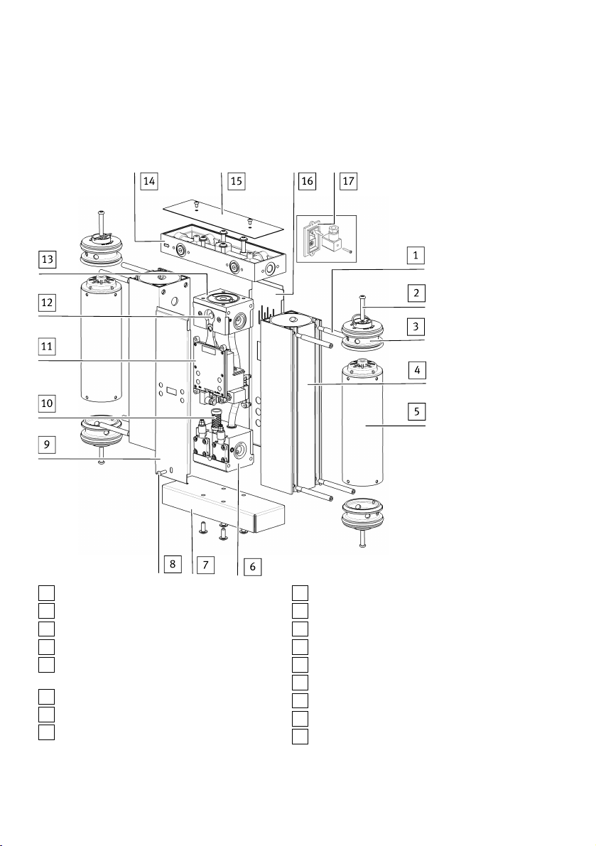
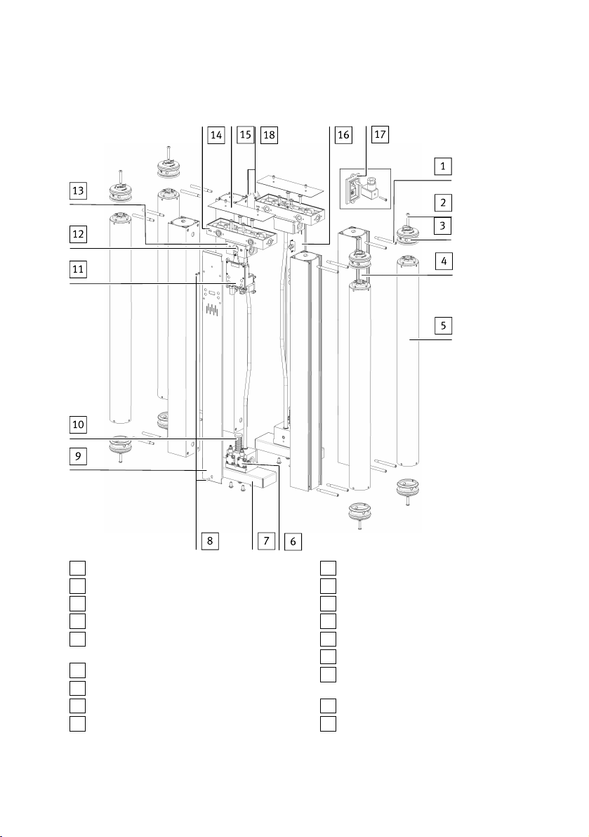
5.2 Design........................................................................................................................... 8
5.2.1 Overview.................................................................................................................8
5.2.2 Electronic controller................................................................................................10
5.2.3 Multi-way distributors.............................................................................................10
5.2.4 Drying agent cartridge with integrated dust filter................................................... 10
5.2.5 Air reservoirs.......................................................................................................... 10
5.2.6 Alarm relay..............................................................................................................10
5.2.7 Air gun nozzles........................................................................................................10
5.3 Control and display elements....................................................................................... 11
6 Function........................................................................................................................12
7 Assembly..................................................................................................................... 13
7.1 Mount micro filter......................................................................................................... 13
7.2 Installing mounting accessories................................................................................... 15
7.3 Exchange connections for inlet and outlet.................................................................... 16
8 Installation.................................................................................................................. 18
8.1 Pneumatic installation.................................................................................................. 18
8.2 Electrical installation.................................................................................................... 19
8.2.1 Connecting supply voltage......................................................................................19
8.2.2 Connecting alarm relay........................................................................................... 21
9 Commissioning............................................................................................................ 21
9.1 Setting device for the pressure range........................................................................... 21
9.2 Commissioning device.................................................................................................. 22
10 Maintenance................................................................................................................ 23
10.1 Overview of maintenance work..................................................................................... 23
10.2 Shut down the device................................................................................................... 23
10.3 Remove covering and mount........................................................................................ 23
10.4 Replace or clean the air gun nozzle.............................................................................. 25
10.5 Cleaning the silencer.................................................................................................... 26
Table of contents

10.6 Resetting the electronic controller.................................................................................28
11 Malfunctions................................................................................................................ 28
11.1 Troubleshooting............................................................................................................ 28
11.2 Diagnostics....................................................................................................................30
12 Disposal........................................................................................................................30
13 Technical data.............................................................................................................. 31
13.1 Technical data, general..................................................................................................31
13.2 Technical data, pneumatic.............................................................................................32
4 Festo — PDAD — 2020-05h

5Festo — PDAD — 2020-05h
1 About this document
1.1 Applicable documents
All available documents for the product èwww.festo.com/sp.
Document Product
Assembly instructions Desiccant cartridge
Tab. 1 Applicable documents
1.2 Product labelling
The product labelling is located on the right side of the device.
2 Safety
2.1 Safety instructions
– Only use the product in original status without unauthorised modifications.
– Only use the product if it is in perfect technical condition.
– Observe labelling on the product.
– Take into consideration the ambient conditions at the location of use.
– Before working on the product, switch off the power supply and secure it against being switched
on again.
Provide complete pressure reduction.
– To protect the drying agent cartridges, make sure that no compressed air is present at the dryer if
the power supply is interrupted for a long time.
2.2 Intended use
The cold-regenerating adsorption dryer is used exclusively for drying compressed air under the spe-
cified operating conditions.
– Set up indoors, protected from the weather.
– Max. relative humidity 80%at temperatures up to 31°C, linear descending to 50%at 40°C.
– Do not use at altitudes above 2000m.
– Set up vertically.
– Collecting condensate.
2.3 Training of qualified personnel
Work on the product should only be conducted by qualified personnel.The specialized personnel must
be familiar with the installation and operation of electrical and pneumatic control systems.
About this document

2.4 Approvals
Classification of dryers as pressure equipment in categories
Type PDAD-09 PDAD-13 PDAD-22 PDAD-51 PDAD-73 PDAD-100
Category I I I I II II
Tab. 2 Classification of dryers as pressure equipment in categories
Information on commissioning and maintenance
– Protect the device and mounting components from mechanical vibrations
– Visually inspect the device for damage at regular intervals. Replace damaged device.
3 Further information
– Accessories èwww.festo.com/catalogue.
– Spare parts èwww.festo.com/spareparts.
4 Service
Contact your regional Festo contact person if you have technical questions èwww.festo.com.
5 Product overview
5.1 Product range overview
Scope of delivery
Micro filter MS6-LFM Connecting kit Power supply socket
Adsorption dryer PDAD Tubing Operating instructions
PDAD
Tab. 3 Scope of delivery PDAD
The dryer is supplied in protective packaging.
Further information
6 Festo — PDAD — 2020-05h

Type Service kit with drying agent cart-
ridges, O-rings, reset disc and instruc-
tion manual
Air gun nozzle set with 3 air gun
nozzles (PDAD-100: 6 air gun nozzles)
PDAD-09 PDAD-09-SP-12000 ADNA-PDAD-09
PDAD-13 PDAD-13-SP-12000 ADNA-PDAD-13
PDAD-22 PDAD-22-SP-12000 ADNA-PDAD-22
PDAD-51 PDAD-51-SP-12000 ADNA-PDAD-51
PDAD-73 PDAD-73-SP-12000 ADNA-PDAD-73
PDAD-100 PDAD-100-SP-12000 ADNA-PDAD-100
Tab. 4 Accessories PDAD
Product overview
7Festo — PDAD — 2020-05h

5.2 Design
5.2.1 Overview
Main components PDAD-09/13/22/51/73
1Retaining screw for air reservoir
2Screw for container seal
3Sealing air reservoir
4Air reservoirs
5Drying agent cartridge with integrated dust
filter
6Lower valve block
7Base plate
8Front covering screw
9Front covering
10 Silencer
11 Electronic controller
12 Air gun nozzle
13 Upper valve block
14 Multi-way distributors
15 Cover sheet
16 Rear covering
17 Mains connection (on the back of the device)
Fig. 1 Structure of PDAD-09/13/22/51/73
Product overview
8 Festo — PDAD — 2020-05h

Main components PDAD-100
1Retaining screw for air reservoir
2Screw for container seal
3Sealing air reservoir
4Air reservoirs
5Drying agent cartridge with integrated dust
filter
6Lower valve block
7Base plate
8Retaining screw for front cover
9Front covering
10 Silencer
11 Electronic controller
12 Air gun nozzle
13 Upper valve block
14 Multi-way distributors
15 Cover sheet
16 Rear covering with cable through-hole for
mains connection
17 Mains connection (inside the device)
18 Connecting screw and seal for connecting
the multi-way distributor
Fig. 2 Structure of the PDAD-100
Product overview
9Festo — PDAD — 2020-05h

5.2.2 Electronic controller
The valve blocks at the top and bottom are actuated by pilot solenoids in the controller, which determ-
ine the pressure and direction of the air flow in the drying agent cartridges.
5.2.3 Multi-way distributors
The standard design of the dryer is configured so, viewed from the front of the device, the inlet open-
ings are on the left and the outlet openings on the right. Different arrangements of the openings are
available by repositioning the opening sockets è 7.3 Exchange connections for inlet and outlet.
5.2.4 Drying agent cartridge with integrated dust filter
The drying agent cartridges contain a drying agent for drying compressed air. The drying agent is in a
transparent pipe with end pieces that is permeable to air at both ends. In the top part of each cartridge
is a 1-micron filter for removing residual dust from the drying agent. The cartridge length varies with
the nominal power of the dryer.
5.2.5 Air reservoirs
The drying agent cartridges are located in an air reservoir made of extruded aluminium. The air reser-
voir is equipped with pressure-resistant end caps. Operating pressure and flow rate through the indi-
vidual cartridges are controlled by the valve blocks arranged between the two air reservoirs. The
regeneration air flow (purge air flow) is controlled via the air gun nozzle on the upper valve block.
5.2.6 Alarm relay
An alarm relay with DIN connection is located on the electronic controller. A visual or audible remote
alarm system can be connected at this connection.
The alarm relay switches in the event of a malfunction or if service is required. Red LED on the display
indicates an error.
When the error is cleared, the alarm relay is reset, but only after the current switching cycle has ended
or the electronic controller has been reset.
5.2.7 Air gun nozzles
For proper and effective operation, a certain amount of purge air must be generated depending on the
operating pressure. The purge air volume is adapted to the operating pressure. by selecting the cor-
rect air gun nozzle.
The air gun nozzles included in the scope of delivery are for the pressure range of 0.7…0.9 MPa
(7…9 bar, 101.5…130.5 psi). An air gun nozzle from the air gun nozzle set is required for the other
pressure ranges è 5.1 Product range overview.
Operating pressure Number of the air gun nozzle
PDAD-09 PDAD-13 PDAD-22 PDAD-51 PDAD-73 PDAD-100
0.4 MPa (4 bar, 58 psi)
0.5 MPa (5 bar, 72.5 psi)
0.6 MPa (6 bar, 87 psi)
9 10 14 23 29 2 x 23
Product overview
10 Festo — PDAD — 2020-05h

Operating pressure Number of the air gun nozzle
PDAD-09 PDAD-13 PDAD-22 PDAD-51 PDAD-73 PDAD-100
0.7 MPa (7 bar, 101.5 psi)
0.8 MPa (8 bar, 116 psi)
0.9 MPa (9 bar, 130.5 psi)
7 8 12 17 24 2 x 17
1.0 MPa (10 bar, 145 psi)
1.1 MPa (11 bar, 159.5 psi)
1.2 MPa (12 bar, 174 psi)
6 7 10 14 17 2 x 14
1.3 MPa (13 bar, 188.5 psi)
1.4 MPa (14 bar, 203 psi)
1.5 MPa (15 bar, 217.5 psi)
1.6 MPa (16 bar, 232 psi)
5 6 9 12 15 2 x 12
Tab. 5 Allocation of air gun nozzles to operating pressure
5.3 Control and display elements
Scoreboard
1LED X (left-hand air reservoir)
2LED Y (right-hand air reservoir)
3LED Z (condensate drain)
4LED POWER (power supply)
Fig. 3
Product overview
11Festo — PDAD — 2020-05h

LED displays
Status Display Meaning
All LEDs off Operating voltage off
LEDPOWER on green
LEDX on green
Cycle regeneration left reservoir
LEDPOWER on green
LEDZ on green
End of regeneration left reser-
voir and condensate drain
LEDPOWER on green
LEDY on green
Cycle regeneration right reser-
voir
LEDPOWER on green End of regeneration
LEDPOWER on green
LEDX flashes yellow
LEDY flashes yellow
Message (pending mainten-
ance) after every 11500operat-
ing hours
Order service kit with new dry-
ing agent cartridges
One or more LEDs flash red Service required or error
è 11 Malfunctions
Tab. 6
6 Function
The operation of the dryer is intended to ensure a uniform, uninterrupted supply of compressed air of
the specified specification.
This function is achieved with 2 air reservoirs that are alternately in the operating cycle. As long as air
is being dried in one of the reservoirs, the drying agent can be regenerated in the second air reservoir
The air flow is routed through the drying agent cartridge of an air reservoir. This removes moisture
from it. A small amount of the dry air is supplied to the other air reservoir as purge air. The purge air
flows through the drying agent cartridge, escapes into the environment via a drain valve and thus
regenerates the drying agent.
The regeneration cycle lasts 120s. The associated drain valve is then closed. As a result, the regener-
ated air reservoir with purge air is brought to system pressure and can switch to the operating cycle.
After a further 50s, the regeneration cycle of the other air reservoir is started at the start of the new
operating cycle.
Function
12 Festo — PDAD — 2020-05h

7 Assembly
7.1 Mount micro filter
To protect the drying agent from contaminated compressed air, the supplied micro filter MS6-LFM
must be mounted on the inlet of the dryer. In the delivery status, the three inlet ports are located on
the left side of the dryer. If the inlet on the right-hand side is required, the multi-way distributor must
be turned in the cover of the dryer è 7.3 Exchange connections for inlet and outlet.
1Inlet side
2Outlet side
3Display of flow direction display (arrows)
Fig. 4 Multi-way distributor - configuration of standard design
Note on mounting position
Regardless of the mounting position of the dryer, the micro filter MS6-LFM must always be arranged
vertically (±5°). Sufficient space must be provided underneath the filter bowl (≥100mm). If installed
horizontally, the dryer must be supported with suitable material.
Vertical installation Horizontal installation
Tab. 7 Mounting types
Assembly
13Festo — PDAD — 2020-05h

Mounting module connector plate
Fig. 5 Mounting the module connector plate
1. Select inlet port. Remove the sealing plug and attach it to the unused inlet.
2. Lightly grease O-ring 2 and place in the groove of the inlet 1.
3. Fasten module connector plate 3 to the inlet with hollow bolt 4. The module connector plate can
be offset by 90°to install the dryer in a horizontal position.
Size Width across flats Tightening torque
y"10 Max. 15Nm
½"14 Max. 18Nm
Tab. 8 Width across flats and tightening torques for hollow bolts
Mount micro filter
Fig. 6 Mount micro filter
1. Insert the flat seal 5 into the slot of the module connector plate 3.
Assembly
14 Festo — PDAD — 2020-05h

2. Insert O-ring 6 into the slot of the micro filter.
3. Place micro filter on the dryer. Observe the flow direction from 1 to 2 during this stage. The num-
bers 7 on the housing of the micro filter serve as an orientation.
4. Mount module connector 8 between micro filter and dryer.
– The protruding edge of the module connector is located at the top.
– Tightening torque of the screws: 1.2 Nm±10%.
Fig. 7
5. Connect the 4 mm tubing 9 (scope of delivery) to the condensate drain of the micro filter. Con-
nect the other end of the tube to the fitting NPQH-L on the back of the dryer at the upper "Con-
densate inlet" port.
7.2 Installing mounting accessories
Note
The mounting accessories are not included in the scope of delivery of the adsorption dryer PDAD.
Wall mounting ABMW-PDAD Foot mounting ABMF-PDAD
Tightening torque: max. 10Nm Tightening torque: max. 10Nm
Tab. 9 Mounting options
Assembly
15Festo — PDAD — 2020-05h

7.3 Exchange connections for inlet and outlet
Configuration of the standard design
The standard design of the dryer is configured so, viewed from the front of the device, the inlet open-
ings are on the left and the outlet openings on the right. Different arrangements of the openings are
available by repositioning the opening sockets.
1Inlet side
2Outlet side
3Display of flow direction display (arrows)
Fig. 8 Multi-way distributor - configuration of standard design
1Inlet side
2Outlet side
3Flow direction (arrows)
Fig. 9 Multi-way distributor - installation in corners
Assembly
16 Festo — PDAD — 2020-05h

Exchange connections
Fig. 10
1. Loosen the retaining screws of the cover and remove cover.
Fig. 11
2. Loosen 4 retaining screws (SW 5) of the multi-way distributor and remove the multi-way distribut-
or.
Fig. 12
3. Turn multi-way distributor180°. Check that the two O-rings are seated correctly in the valve block
and place them on the multi-way distributor. Fasten multi-way distributor with 4 retaining screws
(SW 5).
– Tightening torque max.20Nm.
Assembly
17Festo — PDAD — 2020-05h

Fig. 13
4. Place cover and secure with 2 retaining screws.
– Tightening torque max.1Nm.
Ä
1Inlet
2Outlet
Fig. 14 Position of the ports after replacement
8 Installation
8.1 Pneumatic installation
Requirements
– The dryer is fully assembled and set up in compliance with the operating conditions.
– The micro filter MS6-LFM is mounted.
– The multi-way distributor is mounted with the inlet and outlet at the desired position.
Connecting the dryer
1. Screw the fitting or pipe into the threaded connection of the micro filter.
– Maximum screw-in depth for thread to ISO 228: 12, 0mm
– Maximum screw-in depth for NPT thread: 10, 3mm
2. Collecting condensate.
To do this, connect the tubing with an outside diameter of 4mm to the condensate outlet (NPQH-
L fitting at the lower connection on the back of the dryer). Guide the open end of the tubing into a
suitable collection container.
3. Only for PDAD -...- N:
Screw the supplied NPT adapter with sealing ring into the outlet of the dryer.
– Tightening torque for NPTy: max15Nm
– Tightening torque for NPT½: max18Nm
4. Screw the connecting fitting of the piping into the outlet of the dryer.
Installation
18 Festo — PDAD — 2020-05h

8.2 Electrical installation
8.2.1 Connecting supply voltage
The device can be operated with alternating current (AC) or direct current (DC). Separate connections
are available for the two types of current in the connector socket of the device.
NOTICE!
Destruction of internal electronics
A supply voltage connected to the wrong connection can destroy the internal electronics.
• Apply supply voltage only to the connection intended for this purpose.
• Cover the unused connection.
• Use only the accompanying power supply socket.
Preparing for connection of the supply voltage to the device
1Covering
Fig. 15 Voltage: 100 to 240 V AC
1Covering
Fig. 16 Voltage: 12 to 24 V DC
Notes on the connection
– The connection for the supply voltage on the PDAD-100 is located under the rear covering.
– Cover unused connections.
Installation
19Festo — PDAD — 2020-05h

Establishing power supply
1Phase (+)
2Neutral conductor (-)
3Seal
Fig. 17
1. Before starting mounting work: Switch off power supply.
2. Mount the cable to the power supply socket.
– Use only the accompanying power supply socket.
– The device is double insulated and requires no earthing.
3. Protect the power supply with a suitable external fuse.
Supply voltage 12 V DC 24 V DC 100 V AC 115 V AC 230 V AC 240 V AC
Current intensity 0.8A 0.4A 0.16A 0.14A 0.07A 0.067A
Tab. 10 Current with supply voltage
Installation
20 Festo — PDAD — 2020-05h
Other manuals for PDAD
1
Table of contents
Other Festo Dryer manuals
Popular Dryer manuals by other brands

Electrolux
Electrolux EDE 57150 W user manual

Conair
Conair W Series user guide

Whirlpool
Whirlpool WGD92HEFW1 installation instructions

SPI Supplies
SPI Supplies SPI-DRY Operation manual

KitchenAid
KitchenAid 53-3498 installation instructions

Schulthess
Schulthess Spirit topLine TW 8340 operating instructions