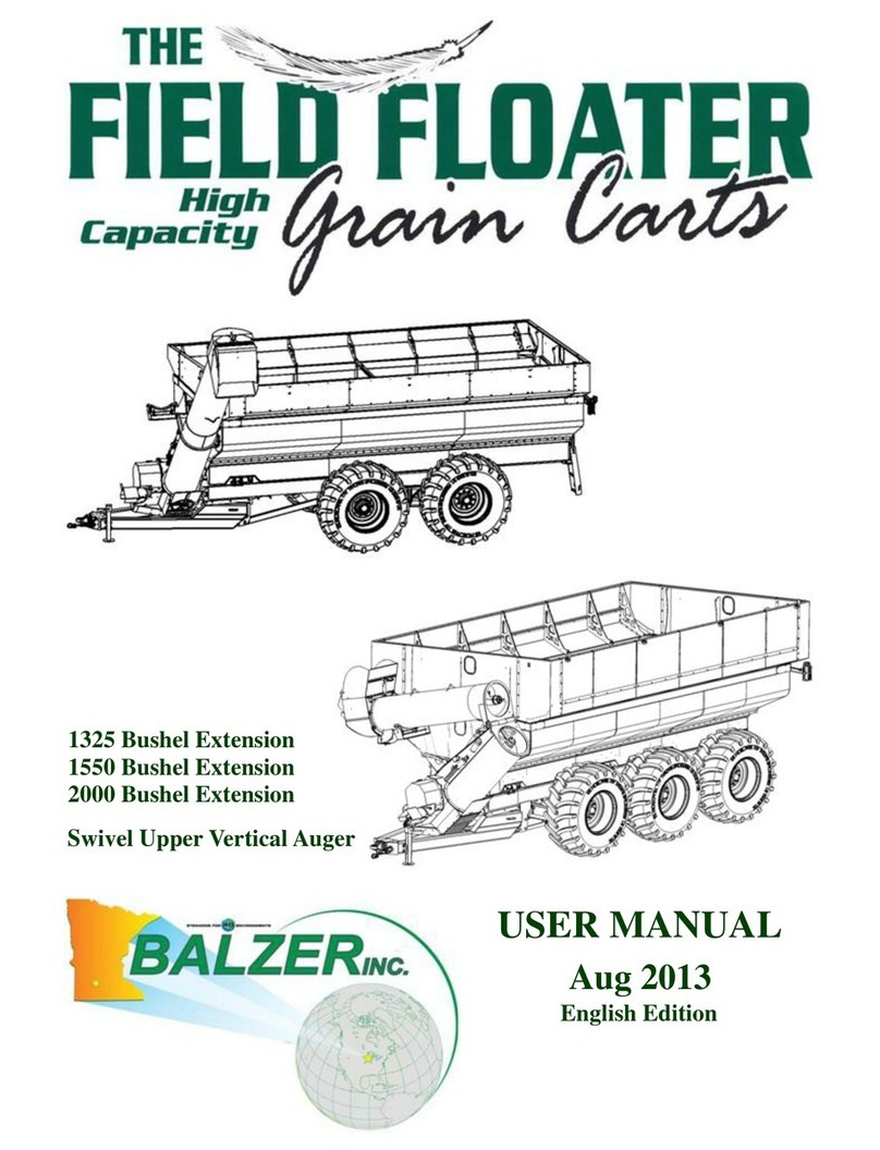
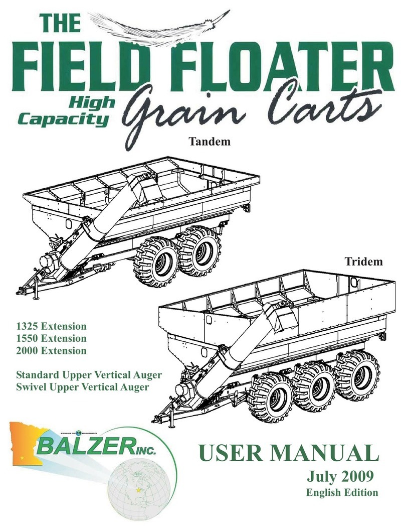
BALZER Field Floater User manual

Assembly Instructions
July 2012

2
Table of Contents
Unpacking........................................................................................................Page 4
Inventory..........................................................................................................Page 5
Assembly..........................................................................................................Page 9
Lubrication.......................................................................................................Page 66
Testing..............................................................................................................Page 70
Index

3
Accuracy
Balzer Inc is dedicated to providing the most reliable and durable AG related products. Balzer
Inc has made every attempt to provide the most accurate and readily understandable information on our
equipment. Due to our continuing efforts to produce the best products available, upgrades and
improvements to our equipment may precede the manual updates. Therefore, contents of this manual are
based on information in effect at the time of publication and are subject to change without notice.

4
Unpacking
Once individual components have been removed from shipping container, the next step is to fold down
the grain cart side panels. This will provide access to parts that have been stored in grain cart box.
Lower side panel till it stops. Side panel will stay in this position. Attach crane to opposite side panel.
Remove temporary side brace and lower into place. Remove any temporary strapping on components
inside the grain cart. Items from inside grain cart can now be removed from cart. Proceed to a full
inventory of parts.
Make sure all personnel are positioned away form side of grain cart be-
ing lowered. Side panels are extremely heavy and may fall suddenly.
DANGER
Field Floater IV Grain Cart
Contents of container may have shifted during transit. Use caution
while unpacking grain cart components.
WARNING

5
Inventory
The individual components of the Field Floater IV grain cart that need to be installed have been broken
down and are labeled with part numbers. Hydraulic hoses are marked on one end or tagged. Individual
shipping configurations will vary due to options ordered with the Field Floater IV grain cart.
BAG LABEL QTY DESCRIPTION PART #
BOX A
OILER 6 5/16X1 1185
4 5/16 FL WASHER 1597
6 5/16 WIZNUT 2081
HOSE HOLDER 2 5/16X1 1185
2 5/16 WIZNUT 2081
2 5/16 FL WASHER 1597
PTO SHEILD 2 5/8X1 1287
2 5/8 LK WASHER. 1640
CLUTCH COVER 3 3/8X1 1/4 1207
5 3/5 WIZNUT 2082
2 3/8 FL WASHER 1598
OPEN & CLOSED IND 2 1/4X1 1164
2 1/4 WIZNUT 2080
ROUND COVERS 8 1/2X1 1/4 1249
8 1/2 WIZNUT 2084
CROSS BRACE 3 1/2X1 1/2 1250
3 1/2 TP LOCK 2539
LADDER 2 5/8X2 1291
2 5/4 FLAT 1602
2 5/8 TOP LK 2546
2 1/2X1 1/2 1250
2 1/2 FLAT 1600
2 1/2 WIZNUT 2084

6
Inventory
BAG LABEL QTY DESCRIPTION PART #
BOX A Continued
LIGHTS 4 3/8X3 1/2 1216
8 3/8 WIZNUT 2082
8 1/4X1 1/4 1165
8 1/4 WIZNUT 2080
AUGER HOUSING TO HOPPER 16 5/8X2 1291
16 5/8 TOP LK 2546
AUGER TO UPPER AUGER HOUSING 8 5/8X1 1/2 1289
2 5/8 TOP LK 2546
UPPER AUGER TO HOPPER 4 3/4X3 1315
8 3/4 FL WAHSER 1603
4 3/4 TOP LK 2593
AUGER LOWER BEARING 4 5/8X3 1295
4 5/8 TOP LK 2546
LOWER AUGER UPPER BEARING 4 1/2X1 3/4 1251
4 1/2 FL WASHER 1600
4 1/2 TOP LK 2539
GREASE BANK COVER 2 1/4X1 1164
4 1/4 FL WASHER 1596
2 1/4 WIZNUT 2080
MANUAL HOLDER 4 1/4X1 1164
4 1/4 FL WASHER 1596
4 1/4 WIZNUT 2080
UPPER AUGER MOTOR MOUNT 4 1/2X1 1/2 1250
4 1/2 TOP LK 2539
UPPER AUGER DEFLECTOR 6 3/8X3/4 1204
6 3/8 TOP LK 2496
MOTOR GEAR SHEILD 2 3/8X1 1/4 1206
2 3/8 WASHER 1598
2 3/8 WIZNUT 2082
AUGER SADDLE 4 5/8X1 1/2 1289
4 5/8 WIZNUT 2085

7
Inventory
BAG LABEL QTY DESCRIPTION PART #
BOX A Continued
HOPPER RH 48 3/8X1 STB 1586
20 3/8X1 EXTRA 1206
HOPPER LH 48 3/8X1 STB 1586
15 3/8X1 1/4 EXTRA 1207
HOPPER FRONT 27 3/8X1 1206
5 3/8X1 1/4 1207
102 3/8 WIZNUT 2082
HOPPER REAR 32 3/8X1 1206
10 3/8X1 1/2 EXTRA 1208
BAG LABEL QTY DESCRIPTION PART #
BOX B
CORNERS 35 5/8X5 1301
35 5/8 TOP LK 2546

8
Inventory
BAG LABEL QTY DESCRIPTION PART #
BOX 1550 & 1325
1500 & 1300 14 3/4X2 1/4 1312
2 3/4X3 1315
32 3/4 FL WASHER 1603
16 3/4 TOP LK 2593
25 3/8 STB 1586
25 3/8X1 3/4 1209
60 3/8X1 1206
70 3/8 FLAT 1598
100 3/8 WIZNUT 2082
2000 . 14 3/4X2 1/4 1312
2 3/4X3 1315
32 3/4 FL WASHER 1603
16 3/4 TOP LK 2593
50 3/8 STB 1586
50 3/8X1 3/4 1209
70 3/8X1 1206
100 3/8 FLAT 1598
120 3/8 WIZNUT 2082
BOX GEAR TOWERS 24 3/4X5 2624
24 3/4 TOP LK 2593
IND TANDEM/TRI AXEL GEAR A 28 1X5 33488
12 1X3 2534
6 1 1/4X8.5 33870
IND TANDEM/TRI AXEL GEAR B 49 1 NUT LOCK 33487
3 1X10 85936
8 1 1/4 LOCK NUT 11479
6 1X6 33494
2 1 1/4X6 TAND BR 2569

9
Front and Rear End Panels
Assembly
Required Hardware Required Tools / Equipment
(56) 3/8” X 1 1/4” Bolt P# 1207
(56) 3/8” Locknut P# 2496 Crane Lifting Tackle Ratchet Strap
Center Punch Wrenches
NOTE It is recommended to have either planking or plywood sheets to line box of grain
cart. It is much easier to move around inside of cart with stable footing.
There must be one person inside of cart and one person on outside of cart to complete this procedure.
Place a ratchet strap or come-along between two side panels and apply enough pressure to help align bolt
holes later. Attach crane to front end panel P# 85762. Raise into place and secure with bolts P# 1207 and
lock nuts P# 2496. Using a center punch, start inserting bolts into holes in upper part of side panel. See
Figure 1.
Figure 1

10
Front and Rear Panels Continued
Assembly
Required Hardware Required Tools / Equipment
(64) 3/8” X 1 1/4” Bolt P# 1207
(64)3/8” Locknut P# 2496
(8) 3/8” Flat Washer P# 1598
Crane Lifting Tackle Ratchet Strap
Center Punch Wrenches
Once all nuts and bolts have been inserted, repeat steps for rear panel. See Figure 2. Insert bolt into
lower part of panels. See Figure 3.
Figure 2
Figure 3

11
Side Panels
Assembly
Required Hardware Required Tools / Equipment
(96) 3/8” X 1” Self Tap Bolt P# 85892 Center Punch Wrenches
Using a center punch, start inserting self tapping bolts P# 85892 into holes in lower portion of side
panels. Start towards the middle or wherever the holes are close. See Figure 1.
Figure 1
P# 85892

12
Corner Brackets
Assembly
Required Hardware Required Tools / Equipment
(32) 5/8” X 5” Bolt P# 1301
(32) 5/8” Locknut P# 2546 Hoist Ratchet Strap Wrenches
Adjustable C-Clamp Center Punch
The corner brackets need to make side and end panels fit tightly together. Position outside cornel bracket
on one corner of cart. Insert bolts P# 1301 through front of bracket. Insert inside corner bracket and
loosely secure with locknuts P# 2546. At this point you may need to use a combination of center punch,
adjustable C-clamp and ratchet strap in order to align the holes in side panel. Tighten all corner bracket
hardware. Tighten all front and rear end panel hardware. See Figure 1.
Figure 1

13
P# 1289
Upper Vertical Auger Cradle
Assembly
Required Hardware Required Tools / Equipment
(4) 5/8” X 1 ½” Bolt P# 1289
(4) 5/8” Toplock Nut P# 2546 Wrenches
Figure 1
Align upper auger cradle P# 85970, insert bolts P# 1289 and secure on inside of hopper with lock nut
P#_2546. See Figure 1.
P# 2546

14
Ladder
Assembly
Required Hardware Required Tools / Equipment
(2) ½” X 1 1/4” Bolt P# 1249
(2) ½” Washer P# 1600
(2) ½” Flange Nut P# 2084
(2) 5/8” X 2 ½” Bolt P# 1293
(2) 5/8” Washer P# 1620
(2) 5/8” Toplock Nut P# 2546
Wrenches
Position ladder P# 85575 at rear of cart, insert bolts P# 1249 and washers P# 1600 through top holes and
loosely secure with flange nuts P#2084 See Figure 1. Insert bolts P# 1293 and washers P# 1620 through
bottom holes and secure with toplock nuts P# 2546. Tighten all bolts.
Figure 1
P# 1600P# 1249
P# 2084
P# 1293 P# 1620
P# 2546

15
Tongue
Assembly
Required Hardware Required Tools / Equipment
(4) 1” X 3” Bolt P# 2534
(4) 1” Lock Nut P# 1779 Hoist Center Punch
Wrenches
Attach crane to grain cart. Raise cart and block in the air. Position Tongue assembly in front of grain
cart. Raise and remove temporary skids from tongue mounting bracket. The same hardware used to
secure temporary skids are used to attach the tongue assembly to the lower frame bracket, P# 2534 & P#
1779. Slide tongue assembly into position and insert the bolts and locknuts, tighten securely. See Figure
1.
Figure 1
P# 2534
P# 1779

16
Suspension Towers
Assembly
Required Hardware Required Tools / Equipment
(4) .75” X 5” Bolt P# 2624
(4) .75” Lock Nut P# 2593 Hoist Center Punch
Wrenches
Position suspension towers and secure with bolts P#2624 and lock-nuts P# 2593. See Figure 1. Repeat
for remaining towers. Hardware totals at top of page are for individual towers only. Totals vary with
Tandem and Tridem suspension.
Figure 1
P# 2534
P# 1779

17
Tandem Independent Suspension
Assembly
Required Hardware Required Tools / Equipment
(2) 1.25” X 6” Bolt P# 2569
(2) 1.25” Lock Nut P# 1780
(2) 1” X 5” Bolt P# 1347
(2) 1” Lock Nut P# 1779
Hoist Center Punch
Wrenches
Position Drag Link and secure to tongue with bolt P# 1347 and lock-nut P# 1779. Attach to front tower
assembly with bolts P# 2569 and lock-nut P# 1780. Repeat for opposite side. See Figure 1.
Figure 1
P# 2569
P# 1780P# 1347
P# 1779

18
Tandem Independent Suspension Continued
Assembly
Required Hardware Required Tools / Equipment
(2) 1” X 5” Bolt P# 1349
(2) 1” Lock Nut P# 1779 Hoist Center Punch
Wrenches
Position Fixed Axle and secure to suspension cylinders P# 900335 with bolts P# 1349, lock-nuts P#
1779, and spacers P#91294. Repeat for opposite side. See Figures 2 and 3.
Figure 2
Figure 3
Fixed Axle
Steering Axle
P# 900335
P# 1779
P# 1349
P# 19294

19
Tandem Independent Suspension Continued
Assembly
Required Hardware Required Tools / Equipment
(8) 1” X 5” Bolt P# 1347
(4) 1” Lock Nut P# 1779 Hoist Center Punch
Wrenches
Attach Upper Drag Link P# 900052 and Lower Drag Link P# 900098 with bolts P# 1347 and lock-nuts
P#_1779. Repeat for opposite side. See Figure 4.
Repeat for Rear Steering Axle.
Figure 4
P# 1347
P# 1779
P# 900052
P# 900098

20
Suspension Hubs and Spindles Without Brakes
Assembly
Required Hardware Required Tools / Equipment
(1) 1 1/4” X 8 1/2” Bolt P# 33870
(1) 1 1/4” Locknut P# 1780 Wrenches
Slide hub and spindle assembly into spindle receiver and secure with bolt P# 33870 and lock-nut
P#_1780. See Figure 1. Repeat for remaining hub and spindle assemblies.
Figure 1
Other manuals for Field Floater
1
Table of contents
Other BALZER Farm Equipment manuals