FFS VIZU VI014HHC User manual
Page 1of 20
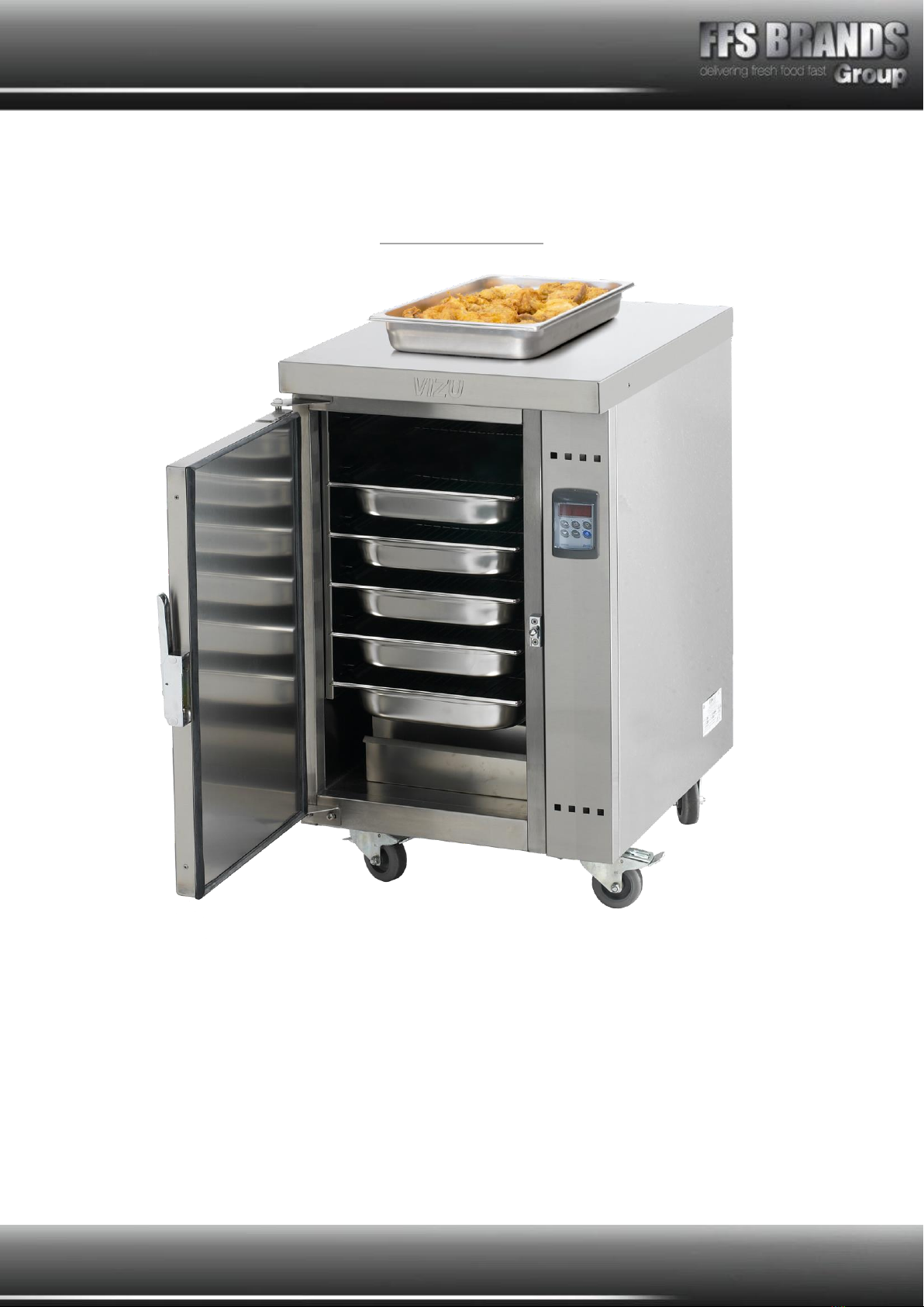
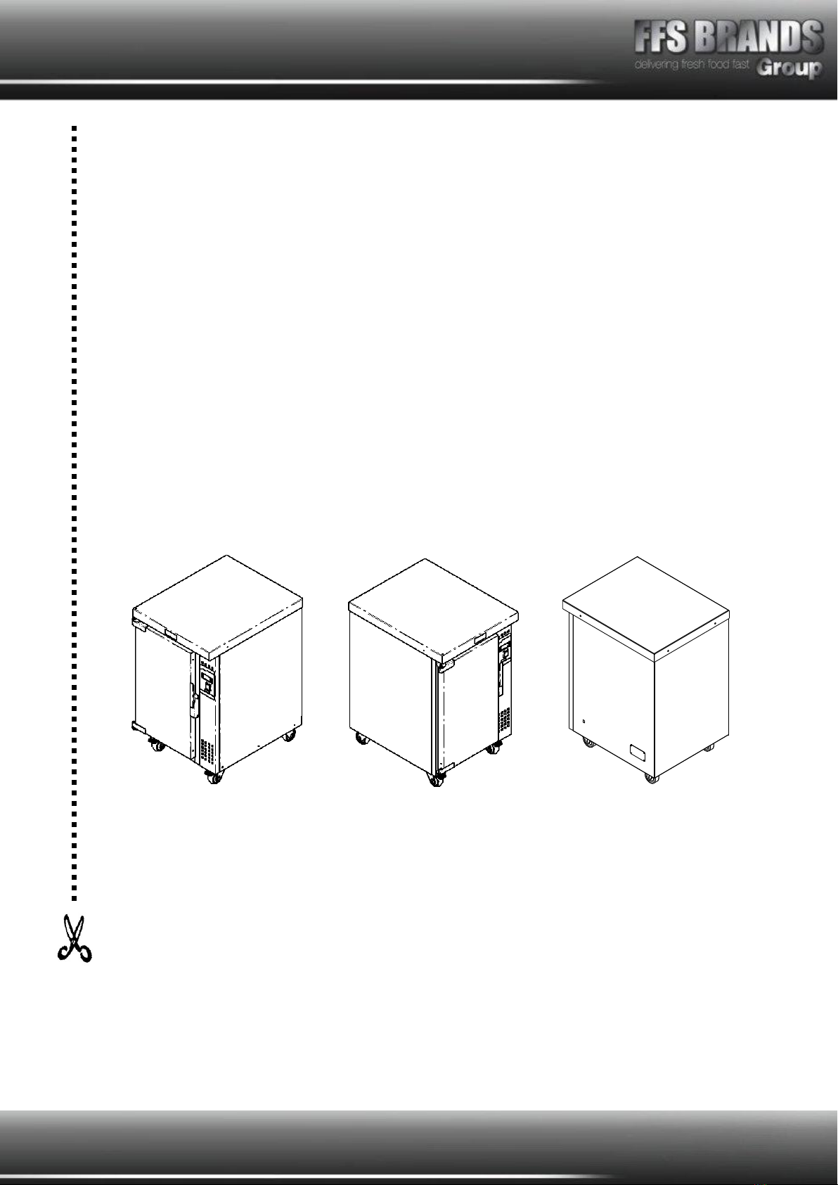
VIZU®Holder
VI014(S)HHC
Thermostatically controlled internal environment with digital display
Fan assisted air convection to improve consistency
Removable internal parts for easy cleaning
Two sizes available in 6 or 8 pan configurations
Mounted on non-marking heavy duty castors
Sealed door to improve internal humidity
Humidity control via water pan venting system

Page 2of 20
Contents
VIZU® Holder ..............................................................................................................1
VI014HHC SPECIFICATION PAGE................................................................................3
Model VI014HHC.......................................................................................................3
VI014SHHC SPECIFICATION PAGE ..............................................................................4
Model VI014SHHC .....................................................................................................4
General Description ...................................................................................................5
Assembly and Installation Instructions.........................................................................5
Switch Controls .........................................................................................................5
Instructions for use ...................................................................................................6
Description of Vizu Humidified Holding Cabinets ...........................................................6
Cleaning instructions - Daily .......................................................................................7
Cleaning of Auto Fill Pass-Thru machines .....................................................................8
Exploded View - VI014HHC ......................................................................................10
Exploded View - VI014SHHC.....................................................................................11
Air Flow Reference ..................................................................................................12
Wiring Diagram .......................................................................................................13
Spare Parts List.......................................................................................................14
FAULT FINDING ......................................................................................................16
Terms and Conditions .................................................................................................17
Claims....................................................................................................................17
Returns ..................................................................................................................17
Damage Claim Form ...................................................................................................18
Warranty ...................................................................................................................19
Page 3of 20
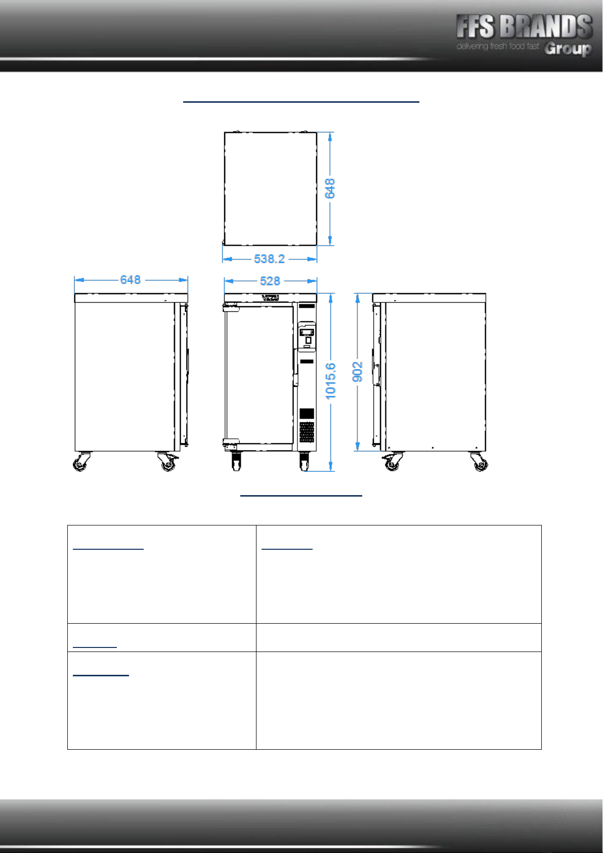
VI014HHC SPECIFICATION PAGE
Model VI014HHC
Dimensions
Height
Width
Depth
Machine
1020mm
540mm
650mm
Weight
66kg
Electrical
Running Amps
Connection Type
International Option
1 phase, 50HZ AC, 2030v, 0.9Kw
3.9 Amps
BSCHUKO 2/3 PIN PLUG
MFEUROCONVERT Plug adapter
Page 4of 20
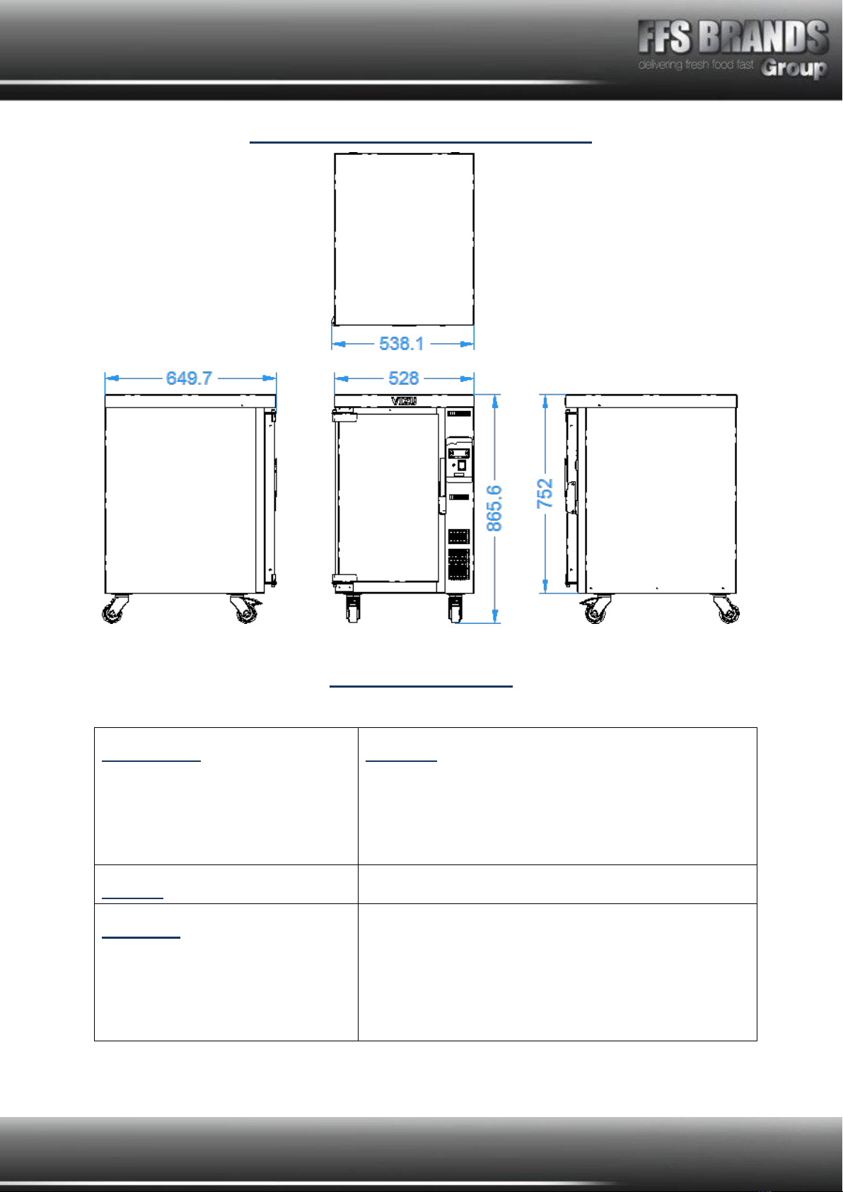
VI014SHHC SPECIFICATION PAGE
Model VI014SHHC
Dimensions
Height
Width
Depth
Machine
870mm
540mm
650mm
Weight
59kg
Electrical
Running Amps
Connection Type
International Option
1 phase, 50HZ AC, 2030v, 0.9Kw
3.9 Amps
BSCHUKO 2/3 PIN PLUG
MFEUROCONVERT Plug adapter

Page 5of 20
All
Vizu Humidified Holding Cabinets
have been tested and checked for proper
operation before leaving the factory.
Upon delivery please check the unit for damage. If the unit is damaged, contact the carrier,
or Fast Food Systems, immediately and file a damage claim (found in the back of the
manual) Please retain all packing materials.
Damage must be reported within 7 days of delivery
General Description
The unit has been designed to hold cooked food products in a controller humidity and
temperature helping to reduce drying and shrinking of the cooked products.
Assembly and Installation Instructions
1. Remove all packing from the unit.
2. Peel off all protective plastic covering from metal
3. Wash all removable parts in warm, soapy water and dry them thoroughly.
4. Check runners are hooked internally in the unit.
5. Slide gastronorm pans into their positions on the horizontal runners.
6. Fit water tray and water tray lid.
Switch Controls
Red Switch –‘ON/OFF’
-Power to the unit
LED Indicator - ‘LED LIGHT’
-Shows the unit has power
Digital Stat –‘Digital display with controls’
-Controls temperature in the cabinet, will be set in the factory to provide the best
possible interior environment. If you need to adjust the settings, please let us
know and we will provide instructions.

Page 6of 20
Instructions for use
1. Ensure Mains power is on –The LED Indicator ‘LED LIGHT’ light should be lit
2. Ensure the water tray has water in it (or empty if you want to hold in dry heat)
3. Turn red ‘ON/OFF’ switch to ‘ON’
4. Leave the machine for 30 minutes to heat (and humidify)
5. Adjust the humidity vents to the desired opening
Description of Vizu Humidified Holding Cabinets
The Vizu Humidified Holding unit must only be used to keep cooked food hot and moist; it
must not be used to re-heat cooked foods.
The machine is suitable for holding cooked meats and fish, and other items.
This unit has a few removable parts, these should be handled with care when using or
cleaning as damage may affect the machines ability to work correctly.
The machine is factory set to 70C. This is adequate to hold cooked food at a safe
and legal temperature (i.e. above 63C)
The red switch light should always remain on as long as the cabinet is plugged in. For
uncovered foods, fill the water tray (situated in the base of the cabinet) with 1 inch (2.5cm)
of hot water. This will allow the heating system to add humidity to the cabinet. Continue to
pre-heat the cabinet for 30 minutes before use. The Vizu Mini/Standard Humidified Holding
Cabinet is now ready to be loaded with hot foods.
Keep the Vizu Humidified Holding Cabinet plugged in while loading and keep the door closed
as much as possible. After loading do not open door again until ready to serve. Before
moving cabinet ensure that cabinet is up to selected temperature, then quickly wheel the
Vizu Humidified Holding Cabinet to the serving area and immediately re-connect to electrical
supply so that the thermostat will automatically 'hold' at the temperature selected.
Do not load or continue to hold food if the thermostat indicates less than 65°C

Page 7of 20
Cleaning instructions - Daily
1. Disconnect the machine from the power supply before cleaning and allow to cool.
2. Remove food gastronorme pans, wire insets, water tray assembly, lower tray and
pan side racks wash thoroughly in warm soapy water, rinse and dry.
3. Doors may be wiped with a soft damp cloth, dry thoroughly taking care not to
damage the seal.
4. Wipe down the inside of the machine with a damp warm soapy cloth, and then dry
thoroughly.
5. Take care not to let any water get into the vents and through to the electrics, you do
not want to soak the machine in water, just use enough water to make the cloth
damp for cleaning.
NEVER use wire wool, scourers, abrasive cleaners, acids or bleach.
DO NOT flood or allow electrical parts to become wet.
DO Dry all surfaces thoroughly removing all moisture.
A stainless steel cleaner/polish may be applied to the exterior.
N.B - For Hard Water Areas
To avoid the risk of scale build up, we advise to use a water softener or de-ionised water for
the water you put into the pan.
Please be aware of these guidelines as scale is not covered by our warranty.
Page 8of 20
Cleaning of Auto Fill Pass-Thru machines
Keep the unit clean by simply wiping the interior and exterior as necessary with a damp
cloth or sponge and a mild soapy solution. NEVER use abrasives, acids or strong cleaners.
DO NOT flood or allow electrical parts to become wet. The interior racks, water tray and
element cover are removable for ease of cleaning. A stainless steel cleaner/polish may be
applied to the exterior to maintain an as-new appearance. Do not use wax or powerful
cleaners on door gasket.
NEVER USE WIRE WOOL –THIS WILL MARK THE STAINLESS STEEL SURFACES
CARE MUST BE TAKEN WHEN CLEANING THE INTERIOR OF THE MACHINE
BECAUSE ELEMENTS, PANELS ETC. MAY REMAIN HOT FOR SOMETIME AFTER THE
HEATING HAS BEEN SWITCHED OFF.
NOTE: - DO NOT USE ABRASIVE CLEANERS OR PADS.
DO NOT USE BLEACH.
Dry all surfaces thoroughly removing all moisture.
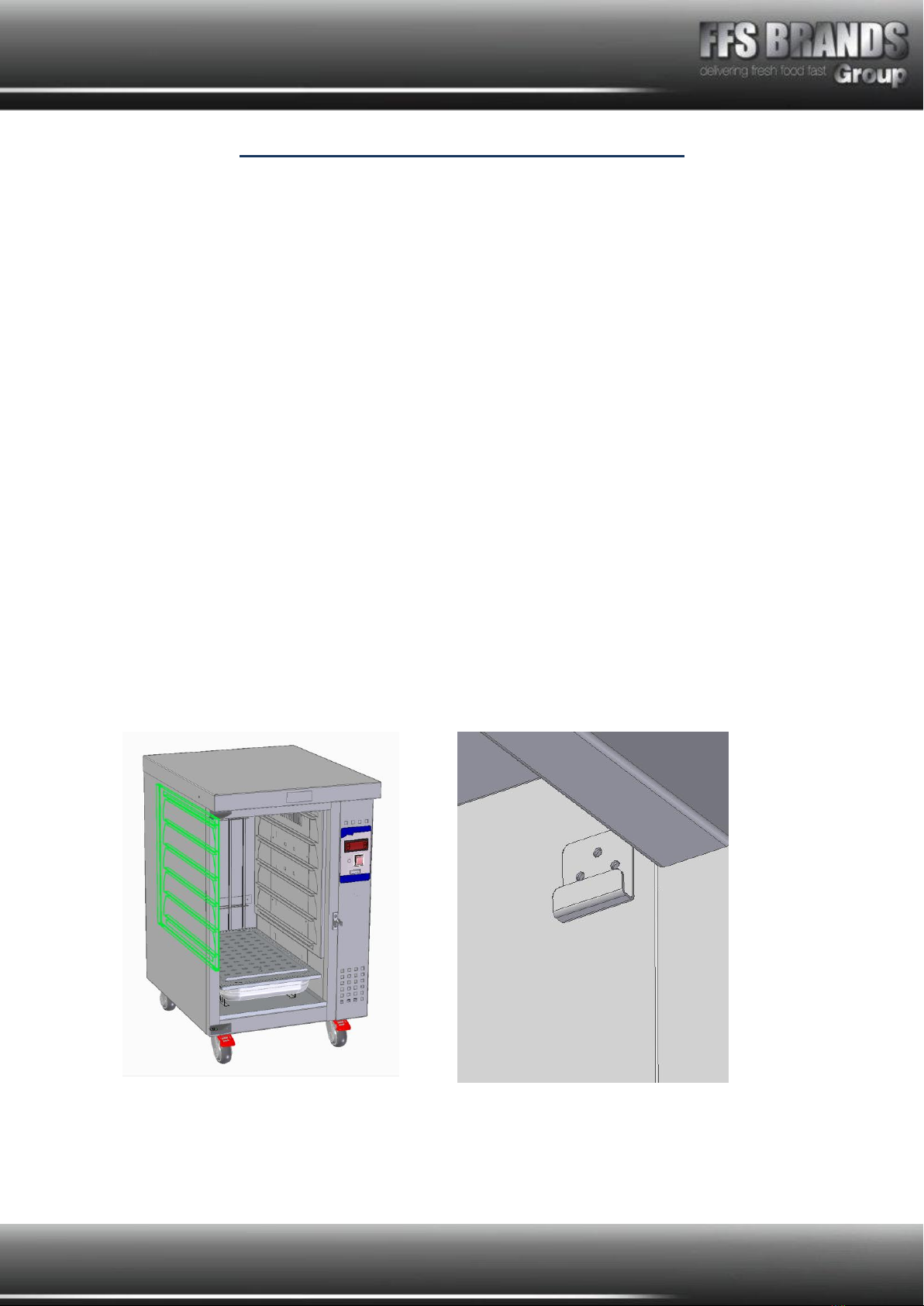
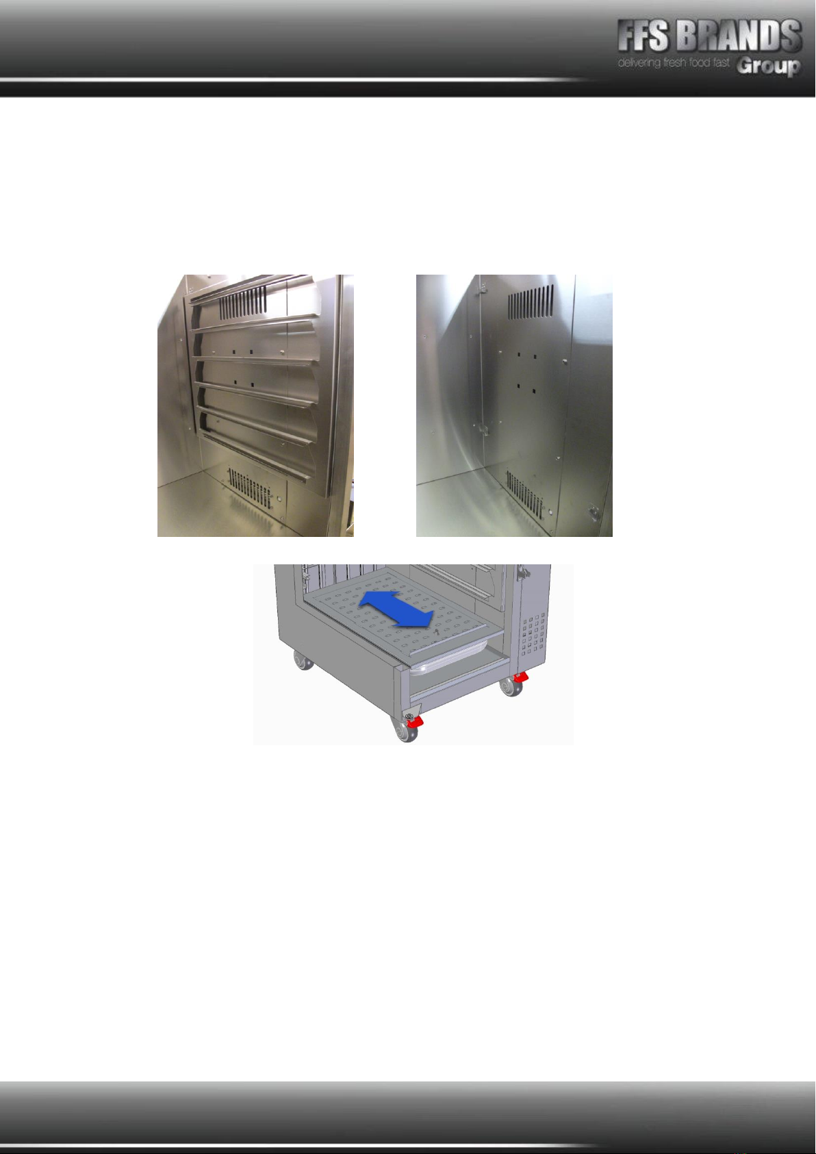
Removal of the tray runners from the inside of the unit
As part of the cleaning procedure the tray runners must be removed to allow cleaning to be
carried out. Fig 1 shows the runners in position.
By lifting the runners frame upwards and inwards it can be moved off the locating hooks,
Fig 2.
Fig. 1 Fig. 2
Page 9of 20
The runner assembly can now be lifted away from the inner side of the machine, Fig 3.
Fig.4 shows the inside of the machine with the runner assembly removed.
The water tray used in the humidified holding cabinets consists of a tray with a cover plate.
Fig. 3 Fig. 4
Fig. 5
The cover plate has a sliding adjustable vent to control the amount of water evaporation.
See Fig. 5. Set to the middle position, and slide open or closed of more or less moisture is
required.
For normal operation the factory setting of the holder is 75C
Temperature / Humidity characteristics
If the temperature of the holder is changed then the characteristics of the unit will change
too. Typically the humidity will be affected by changes to the temperature.
If the temperature is altered then experimentation will be required to see what water levels
(if any) are required, as well as the position of how open or closed the vents are.
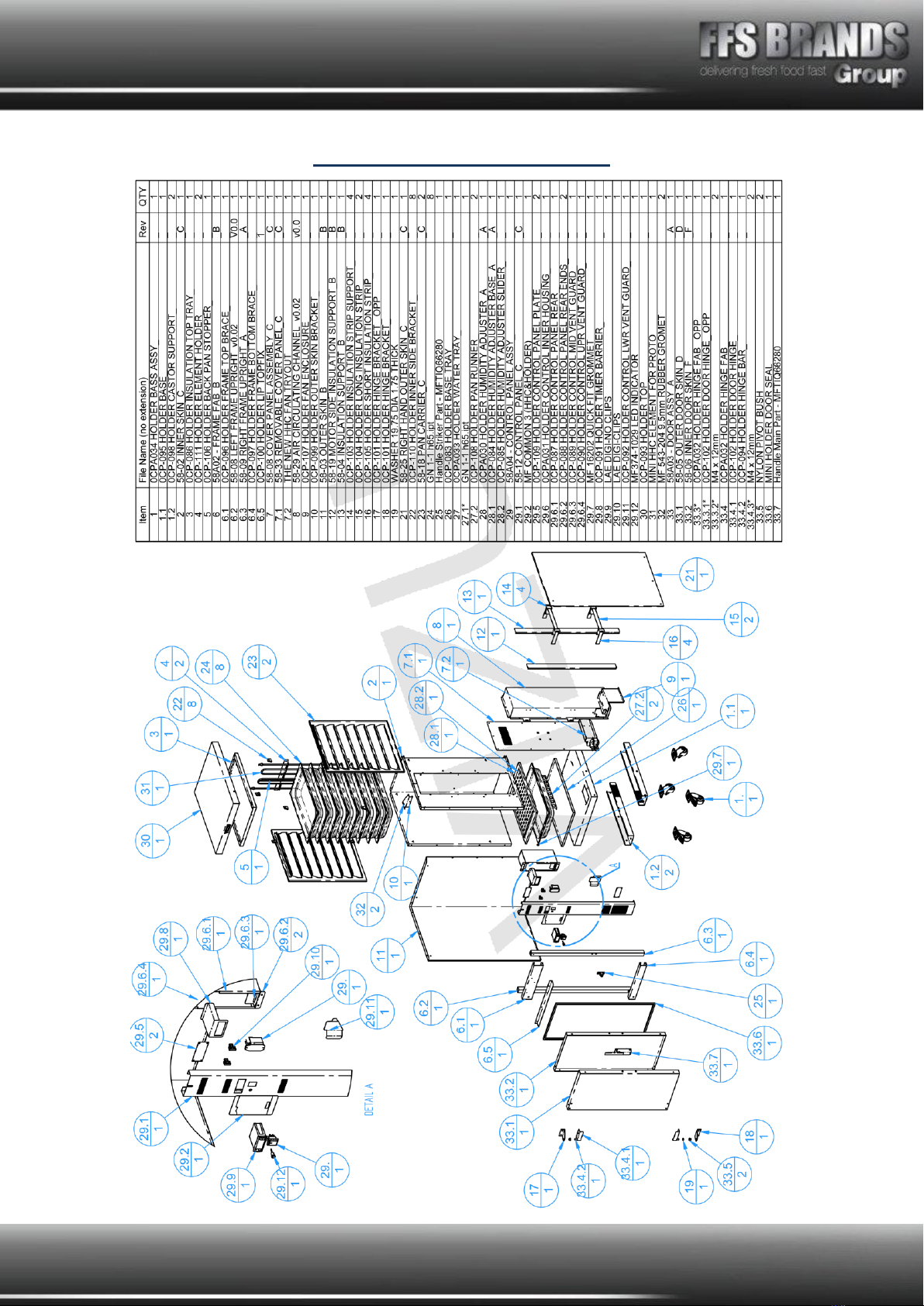
Page 10 of 20
Exploded View - VI014HHC
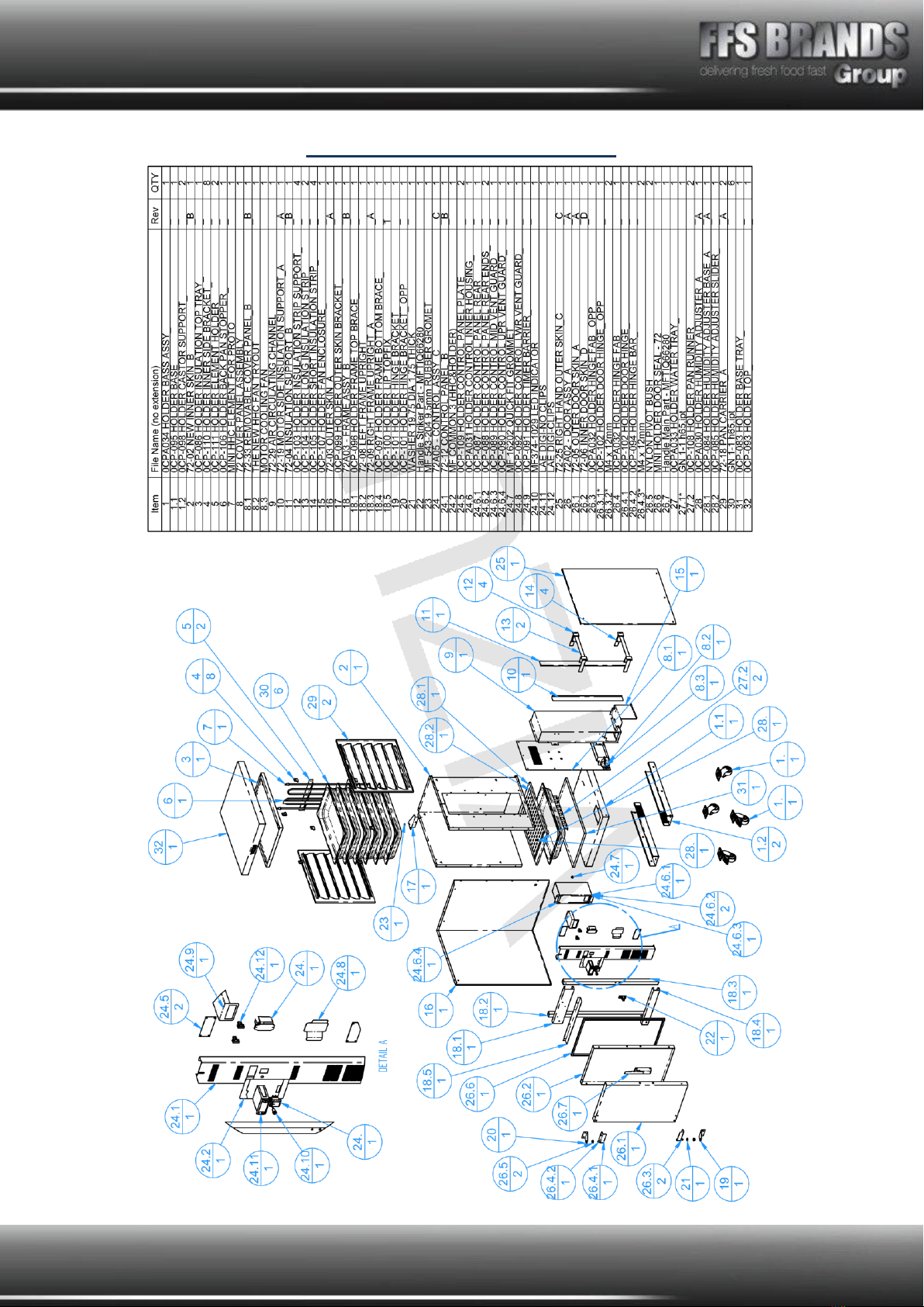
Page 11 of 20
Exploded View - VI014SHHC
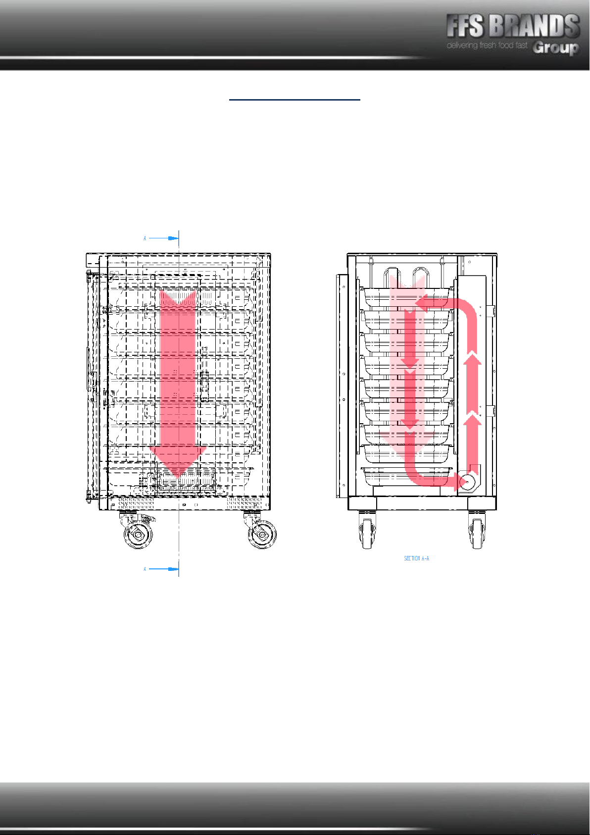
Page 12 of 20
Air Flow Reference
Internal Air flow is controlled by a centrifugal fan mounted at the bottom of the machine.
Diagram shows correct air flow for MF2701060286A Fan.
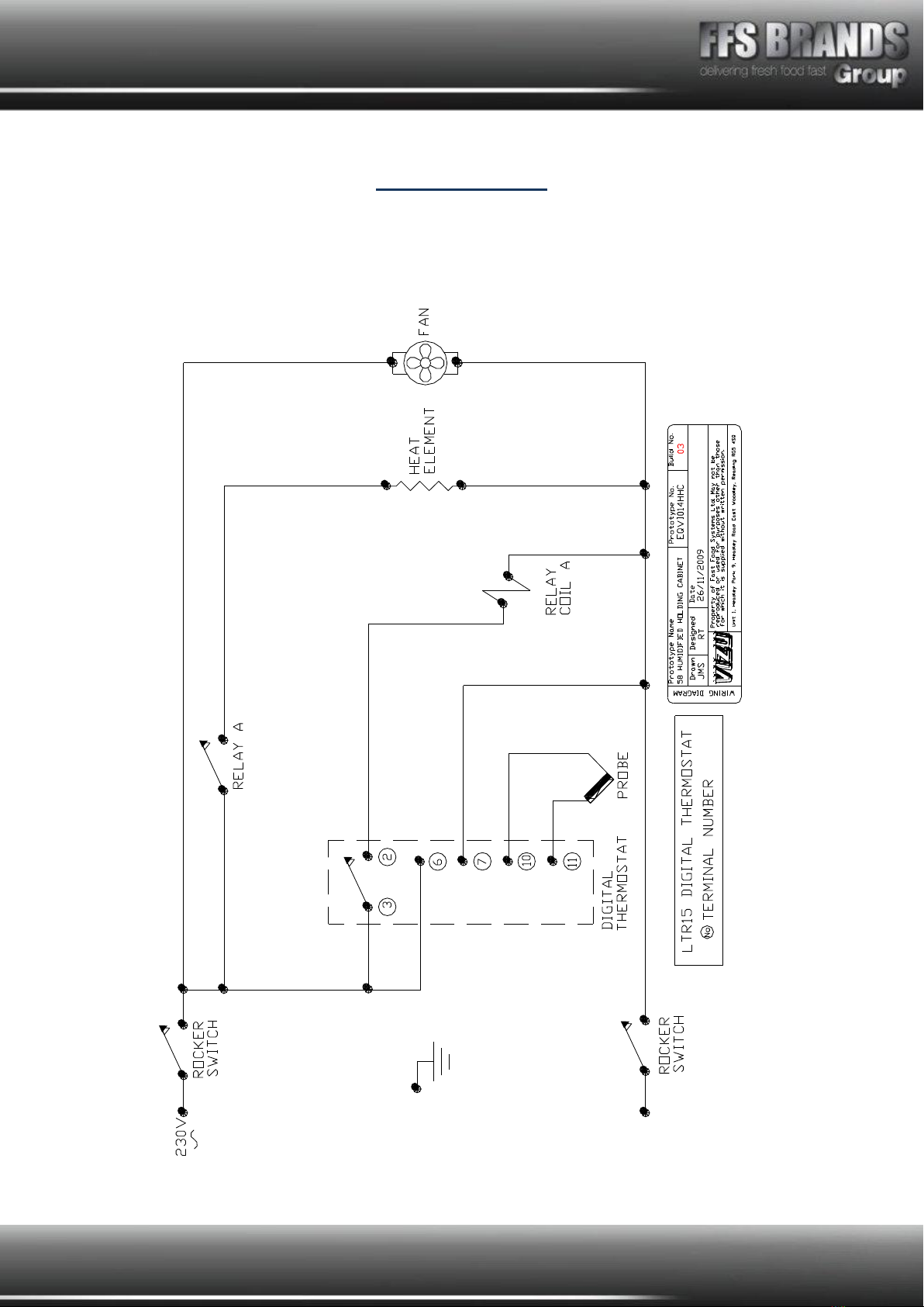
Page 13 of 20
Wiring Diagram
Page 14 of 20
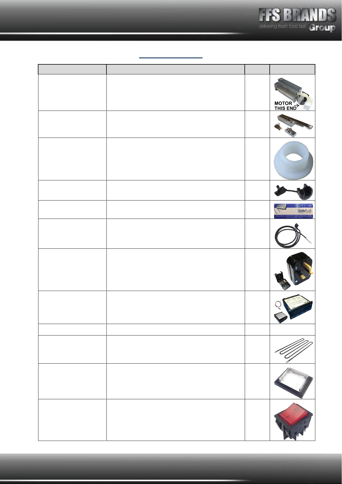
Spare Parts List
PART NO.
DESCRIPTION
QTY.
IMAGE
MF2701060286A
Electric Motor And Scroll Fan
1
MFDP2074-13
Latch And Strike Complete Set
1
MF08-10-11
Nylon Pivot Bushes 1092540000Vr
2
MF817-8877
Black Nylon 66, strain relief cable bush
1
MFCOMMON1
Label 5 140mm x 53mm
1
BESCHUKO
H05Rr-F 2Mtr. Rubber C032
1
MFEUROCONVERT
Euro to UK converter plug In black 19-1032
1
MFMTR11TIRES
Ltr-5Tsre-A(P) Digit Therm. With Probe
1
MFVI014SHHCINS
Mini Holda Insulation
1
Ztbc –oos
MFMINIHHCELEMENT
800W 230V Humidified Holda Element
1
VILE14
Switch cover / bezel HD2/HD4 MFF1025 /
MF1026
1
VISW17
Rocker switch HD2 Revolva HD4 MFC1553ALR
1
Page 15 of 20
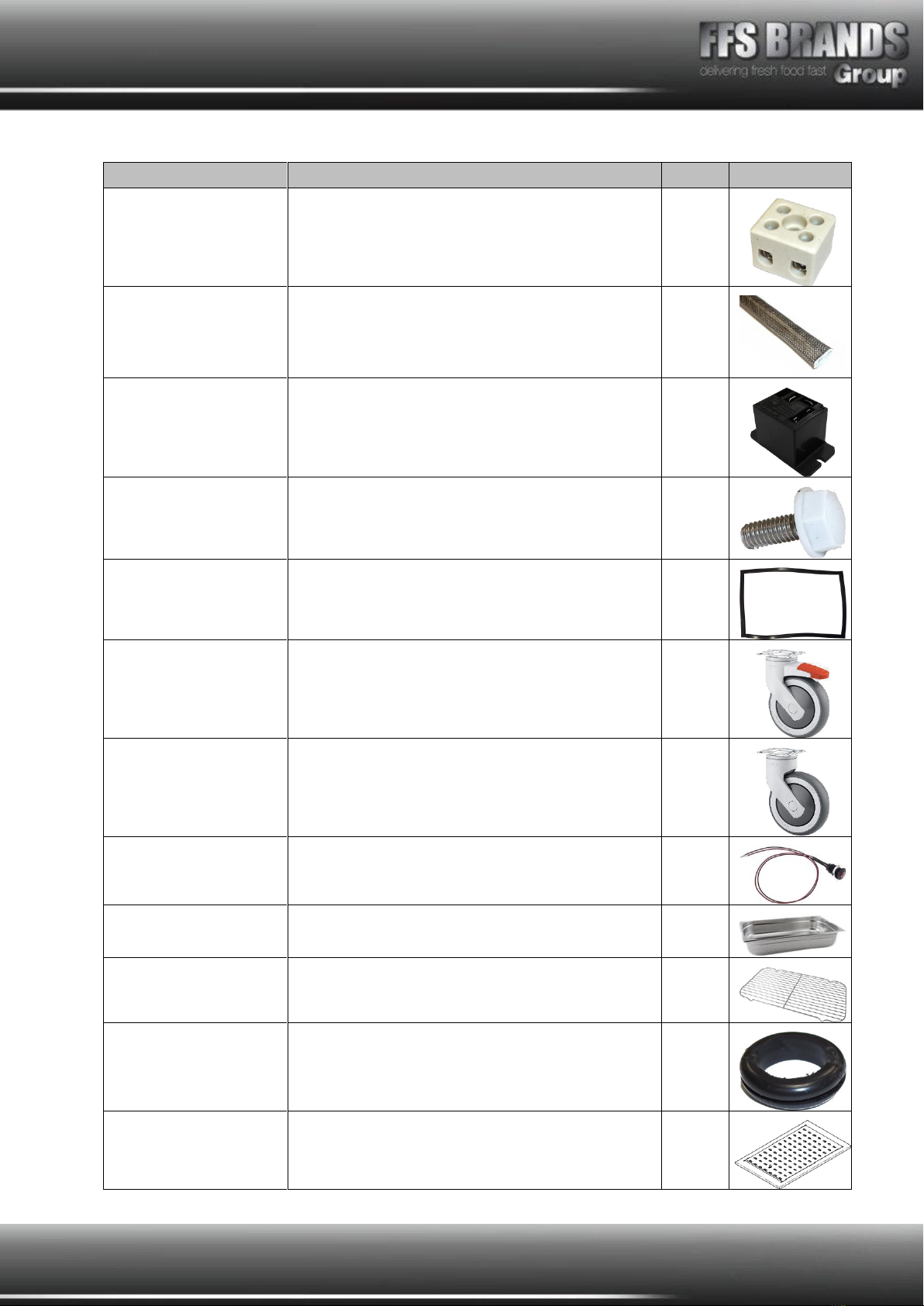
PART NO.
DESCRIPTION
QTY.
IMAGE
MF354Z
2 Pole 5amp term block TB06
2
MFOHSL01
High temperature sleeving
1
MF376-925
Relay 65-31 Holda / HD4 691-2124 Zsp-No
1
MFVC-14
Socket drive Sh/MSM4GY1011SS0100
1
VI06-378
Door Seal Vizu Holda
1
MFMKLJS75PTEK80
Swivel Castor With Break 75mm
2
MFMKLS75PTEK80
Swivel Castor No Break 75mm
2
MF374-1029
10mm low profile lens indicator 230VAC
1
GSGAST90022
1/1GN pan 65mm deep
7
GSGAST160
Stainless steel wire inserts for gast/pans
6
MF543-204
9.5mm Grommet
2
MF0CPA030
ADJUSTABLE HUMIDITY ADJUSTER
1
Page 16 of 20
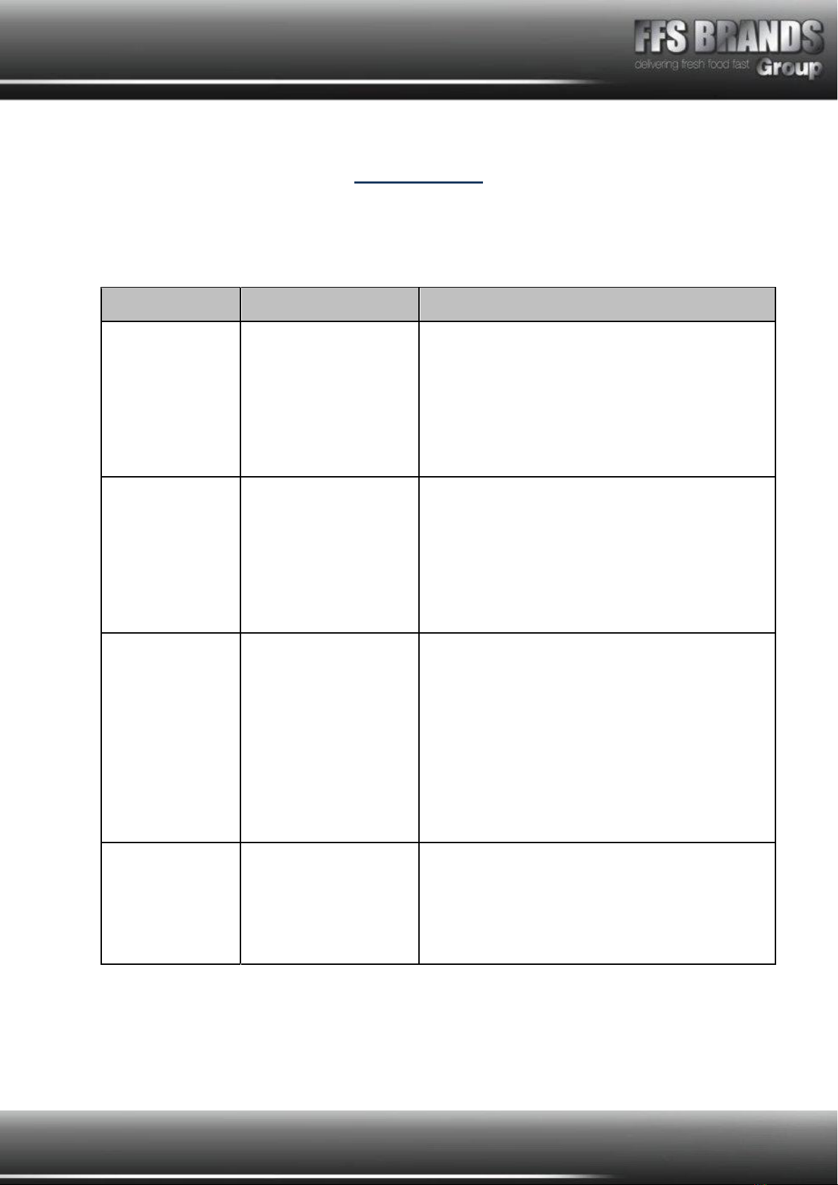
Fault Finding
Any servicing must only be carried out by qualified personnel.
Unit must be removed from electrical supply before servicing.
Problem
Probable Cause
Solution
1. Indicated
ON/OFF switch
does not light up
No power to machine.
ON/OFF switch faulty
Check machine is plugged in and switched on.
Check fuse in 13a plug.
Check circuit breaker at main supply board is in
(ON).
Check Switch
Replace switch.
2. Digital
thermostat does
not indicate
temperature
reading.
ON/Off switch OFF
ON/OFF switch faulty
Digital thermostat
faulty
Switch ON
Replace switch
Unit has overheated, allow to cool
Replace if thermostat
3. Unit does not
heat up.
No power to machine
ON / OFF switch off
ON / OFF switch faulty
Digital thermostat
faulty
Switching relay faulty
Heat element faulty
See section 1.
Switch ON
Replace Switch
Replace thermostat
Replace relay
Replace element
4.Machine does
not heat up,
alarm shown in
digital
thermostat
As indicated
Identify and correct

Page 17 of 20
Terms and Conditions
Claims
No claim shall be entertained by the Company unless made in writing. Claims arising from
damage or partial loss in transit must reach the Company within 7 days from the date of
delivery. Claims for non-delivery must reach the Company within 10 days from the date of
dispatch. All other claims must reach the Company within 7 days. Damaged goods must be
retained for inspection/collection.
Returns
The Company does not operate a returns policy unless the goods are defective:
In circumstances where the Company agrees to accept return of goods, a charge of 25% of
the invoice value will be made.
Page 18 of 20
Damage Claim Form
Machine: MINI/STANDARD HUMIDIFIED HOLDING CABINETS
Product code: VI014SHHC & VI014HHC
Customer name……………………………………………………………
Date of delivery……………………………………………………………
Machine serial number…………………………………………………
Damage comments………………………………………………………
……………………………………………………………………………………………………………
……………………………………………………………………………………………………………
……………………………………………………………………………………………………………
……………………………………………………………………………………………………………
………………………
Please indicate on the picture where the unit is damaged
Courier name…………………………………………………………………
Please cut this page out and post to Fast Food Systems
(The address is on the back of this manual)

Page 19 of 20
Warranty
UNITED KINGDOM AND REPUBLIC OF IRELAND
Excepting where otherwise specified all products are subject to 12 months parts and labour
warranty Goods found defective will be repaired, credited or replaced without charge
according to the terms of the Company’s standard warranty, provided written notice is given
within the guarantee period. In no case will the company be liable for repairs made without
its knowledge or sanction, or for indirect damage, or any consequential loss or expense
incurred by purchasers.
Fast Food Systems Ltd, warrants to the original purchaser that the equipment supplied to be
free from defective materials or workmanship for a period of 12 (twelve) months.
The following are NOT covered by warranty:
1. Failure or breakdown caused by incorrect installation.
2. Glass parts, electric lamps or door seals.
3. Adjustment or calibration of controls - this is a routine maintenance function.
4. Abuse or misuse, including cleaning.
5. Warranty labour is only carried out during normal working hours; calls attended to out
of hours may be subject to surcharges.
6. The warranty will commence either on installation or 1 (one) month from date of
dispatch - whichever is the sooner.
7. Warranty on spare parts purchased for equipment outside of the warranty period is 3
(three) months from date of sale.
8. Any faulty spare parts replaced under warranty must be returned with 7 days of
supply.
9. Warranty is non-transferable.
Fast-Food-Systems Ltd will not be held responsible, financially or otherwise, for any loss of
business as a result of equipment breakdown.
Page 20 of 20
Fast Food Systems Limited
Manufacturer & Distributor of Catering Equipment
Unit 1 Headley Park 9 Headley Road East
Woodley Reading Berkshire RG5 4SQ
Tel: 0118 944 1100 Fax: 0118 944 0350
Website: www.fast-food-systems.com
ISSUE 13 : 15.08.19
Model Number………………………………
Order ID/Job No……………………………
Machine serial number……………………
Date of Manufacture ……/………/………
Date of delivery……/………/……
Date of Commissioning……/………/……
This manual suits for next models
1
Table of contents


