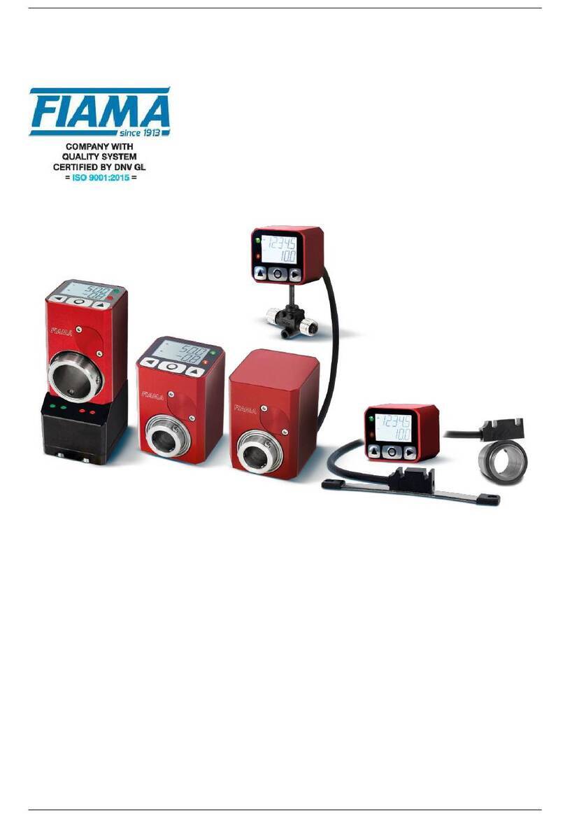
FIAMA EP43NET User manual

Hollow shaft display with fieldbus EP4-NET
08/09/22 EP4NET_1.2_ing.doc rev: 1.2 page: 1/13
USER AND MAINTENANCE MANUAL EP43NET EP46NET
ELECTRONIC HOLLOW SHAFT DISPLAY
WITH FIELDBUS
(Profinet, EthernetIP, EtherCAT, IO-Link)

Hollow shaft display with fieldbus EP4-NET
08/09/22 EP4NET_1.2_ing.doc rev: 1.2 page: 2/13
Manual purpose
This manual has been designed by the Manufacturer to provide the necessary information regarding the
EP43NET / EP46NET display to those who are authorized to carry out safely its installation, maintenance,
removal and disposal. All the necessary information for the buyers and planners can be found in the Sales
documentation. In addition to adopting good technical construction practices, the information should be read
carefully and strictly applied. Failure to observe this information could cause risks for the health and safety of
people and economical damage. This information, provided by the Manufacturer in the original language
(Italian) is also available in other languages to satisfy legislative and/or commercial needs. This manual must
be kept in good conditions by a responsible person in an ideal place so that it is always available for
consultation. In case this manual is lost or deteriorates, a replacement should be requested directly from the
manufacturer indicating the manual’s code. This manual reflects the state of the instrument at the time of
input on the market: however the manufacturer reserves the right to make changes, add or improve the
manual without further notice.
Identification of the equipment
The identification label is applied on the instrument.
To determine the identification code of the instrument, consult the sales documentation.
Environmental conditions
Temperature range: min. 0°C, max. + 50°C.
It is forbidden to use the instrument other than for its specific use and in potentially explosive conditions or
where anti-explosive elements are required.
Storage
Here below are some references to be followed for the storage of the instrument:
Avoid environments with excessive humidity and those exposed to bad weather (avoid open areas).
Avoid putting the instrument directly on the ground.
Store the instrument in its original packaging.
Conformity declaration and EC marking
The instrument respects the following Communitarian Directives:
2014/30/EU Electromagnetic compatibility, 2011/65/EU RoHS.
Maintenance
The instrument does not need particular maintenance except cleaning, only with a soft cloth dampened with
ethyl alcohol or water. Do not use hydrocarbon solvents (petrol, thinners, etc.): the use of these products
could affect the proper function of the instrument.
Repairs should be done only and exclusively at the FIAMA technical assistance centre.
Calibrations and tests
It is advisable to calibrate the instrument periodically, once every working year.
To conduct calibration, follow the calibration procedure described in the present manual.
Technical Support
For any kind of technical assistance, contact the sales department of the Manufacturer directly indicating the
information given on the identification label, the number of hours used and the type of defect.
Manufacturer’s responsibility
The manufacturer declines any responsibility in case of:
•Using the instrument contrary to applicable national safety and accident-prevention laws.
•Incorrect installation, inobservance of, or incorrect procedures in contrast with the instructions
provided in the present manual.
•Defective electrical power supply.
•Modifications or tampering.
•Operations carried out by untrained or unqualified staff.
The safety of the instrument also depends on the strict observance of the procedures indicated in the
manual: always operate the instrument in its functioning capacity and carry out a careful routine maintenance.
•All phases of inspection and maintenance should be carried out by qualified staff.
•The configurations indicated in the manual are the only ones permitted.
•Do not attempt to use the instrument in anyway which is contrary to the indications provided.
The instructions in this manual do not substitute but are a complement to the obligations of the current
legislation regarding safety laws.

Hollow shaft display with fieldbus EP4-NET
08/09/22 EP4NET_1.2_ing.doc rev: 1.2 page: 3/13
Installation
Before installing the instrument, heed the following warnings:
a) Connect the instrument strictly following the instructions of the manual.
b) It is the responsibility of the user to check, before using, the correct setting of all parameters of the
instrument to avoid damage to persons or things.
c) The instrument CANNOT function in a hazardous environment (inflammable or explosive).
The unit contains parts sensitive to electrostatic charge, therefore handling of the internal electronic cards
has to be carried out with appropriate care to avoid permanent damage.
Description
The electronic position indicator EP43NET / EP46NET, which includes within the same case a position
transducer and a display unit, is a device for measuring linear or angular movement which is compact, easy
to install, and applicable in several types of industry (packaging, woodworking, aluminum, sheet metal, etc.)
The fieldbus output which is available in the Profinet, EthernetIP, EtherCAT, and IO-Link versions allows
network connection to a PLC or a remote supervision system.
This device simplifies and quickens format changeover on machines with manual axis adjustment (for ex.
with hand-wheels).
The backlit LCD display has two lines: the first shows the current value and the second shows the value to be
reached in the new machine configuration.
The target value is communicated to the EP43NET / EP46NET via a serial interface with the PLC to allow a
manual changeover by handwheel. The two LEDs indicate if the target value has been reached or not.
With the 3 frontal keys it is possible to program the value on the display for every rotation of the hollow shaft
and activate the following functions: reset/preset of the value, absolute/relative measurement, mm/inches
conversion, and reading range in degrees.
The instrument must be powered externally with a 10-30VDC power supply and is equipped with an internal
backup battery which assures that the value is updated and saved, even in the absence of external power, for
a period of 6-8 years. When external power is not present, the display is off and the serial port is inactive.
The robust case of the EP43NET / EP4NET is made of aluminum alloy which is billet machined and anodized
while the hollow shaft is made of stainless steel and is supported by ball bearings.
Programming
To access programming of the parameters, keep pressed until
appears on the display. Then press O
2 times and 3 zeroes will appear. The first digit on the right will blink: using (digit increase) and. (digit
selection) insert the pass code which is 273 and confirm with O. In case of incorrect insertion of the
password, the unit exits the programming mode.
The various parameters can be scrolled with and appear in the following order:
0
00
0 value to be displayed after one complete rotation of the shaft
+%
+%+%
+% number of decimal places
//
////
// button activation mode
.
..
. preset quote
%.
%.%.
%. count direction
,,
,,,,
,, backlash compensation value
//
////
// target value
+,
+,+,
+, tolerance around target value
%%.
%%.%%.
%%. device address (only for PowerLink, EtherCAT version)
To modify the selected parameter press Otwo times (the first time displays only the value). With and set the
desired value and confirm with O.
To set a negative number, press until the last digit on the left blinks then press once again and after press so
that the minus sign will appear.
To exit programming press .

Hollow shaft display with fieldbus EP4-NET
08/09/22 EP4NET_1.2_ing.doc rev: 1.2 page: 4/13
Value to be displayed after one complete rotation of the hollow shaft: 0
00
0
This parameter, together with the following one, defines the value which is displayed after one rotation of the
hollow shaft. The allowable range is from 0,0001 to 99999. The decimal place is set after programming the
last digit on the left: after pressing, the decimal place will blink and with it can be moved to the desired
position. Confirm with O.
Number of decimal places: +%
+%+%
+%
It is the number of decimal places to visualize on the display, allowed range from 0 to 4.
Example 1: if each rotation of the hollow shaft will cause a displacement of 50, set 0
00
0=50 and +%
+%+%
+%=0.
Example 2: if each rotation of the hollow shaft will cause a displacement of 12,345 and the desired output on
the display is 12.3, set 0
00
0=12.345 and +%
+%+%
+%=1.
Button activation mode: //
////
//
This parameter programs the button functions.
The value is a number with 3 digits, each corresponding to a button: the digit on the right sets the O button,
the digit in the middle sets while the last digit on the left sets.
The possible values are in the following table:
VALUE O
0 Not active Not active Not active
1 mm/inch conversion Reset ABS/REL measurement
2 Not active Preset Not active
3 Not active Fast Preset Not active
4 Not active Delayed Reset after 3s (*) Not active
5 Not active Delayed Preset after 3s (*) Not active
(*) Delayed means that to activate the function (reset or preset), it is necessary to keep Opressed for
approximately 3 s.
1) Reset: reset function of the displayed value; after pressing Othe displayed value is set to zero.
2) Preset: preset function of the displayed value; after pressing Othe displayed value becomes equal to the
value in the ./
././
./
parameter, which can be set immediately after //
////
//(when the digit on the right is set
to 2).
3) Fast Preset: the fast setting of the displayed value on the display; after pressing O, ./
././
./ appears and
pressing 2 times Oit is possible to set the value directly (use and then confirm with O). This function is useful
when the displayed value must be corrected often.
4) Delayed Reset: to activate the function reset it is necessary to keep Opressed for approximately 3
seconds
5) Delayed Preset: to activate the function preset it is necessary to keep Opressed for approximately 3
seconds
ABS/REL measurement: Enables switching from an absolute to relative value; after pressing, the displayed
value is temporarily set to zero to measure a relative motion of the shaft. On the display the rel icon indicates
that the current display is relative to the reference point that has just been created. Pressing again causes the
absolute value to be displayed and the abs icon will appear.
Note: The ABS/REL function is enabled only if the measurement is in mm units.
mm/inch conversion: Pressing converts the measurement from millimeters to inches and back. When in
inch mode, the inch icon will appear and the displayed value will have an additional decimal place. When the
parameter +%=4 the mm/inch conversion is not available.
Count direction %.
%.%.
%.
It sets the count direction, allowed values are 0 or 1.
By setting 0, the displayed value increases turning the shaft clockwise.
By setting 1, the displayed value decreases turning the hollow shaft clockwise.

Hollow shaft display with fieldbus EP4-NET
08/09/22 EP4NET_1.2_ing.doc rev: 1.2 page: 5/13
Target Value //
////
//
Value shown on the first line of the display which indicates the position which must be reached by manual
adjustment.
Backlash compensation value ,,
,,,,
,,
If set different to zero, at each inversion of the rotation direction, the displayed value does not change until
the shaft completes a rotation which is equal to or above the backlash compensation value.
Set a positive value for backlash compensation in the forward direction and a negative value for
compensation in the reverse direction.
Tolerance around target value+,
+,+,
+,
When the actual value reaches inside the window around the target value (which is defined by the tolerance)
the red LED is turned off the green LED is turned on.
Example: with target value //
////
//=50 and +,
+,+,
+, =10, the green LED is on between 40,1 e 59,9.
Address device %%.
%%.%%.
%%.
This is the identification address of the unit, it must be unique for every device connected to the bus network,
acceptable values from 1 to 247.
ADJUSTMENT OF DISPLAYED VALUE
After the installation of instrument on the machine and setting of all parameters, in order to visualize on the
display the correct value it is necessary to carry out the reset or preset.
Position the shaft in a position where the correct measurement that has to be visualized is known exactly (for
example the stroke end point) or measure the position in that position of the shaft. Program parameter
+//
+//+//
+// with value 3 in the first digit on the right and exit programming.
Now press Oand ./
././
./
will appear, press again 2 times Oand set the correct value to display, then confirm
with O The display will now show the desired value.
If the required value is zero, instead of the preset function it is possible to use the reset function by setting 1
in the first digit on the right in the //
////
//
parameter so that pressing Owill bring the displayed value to zero.
Now that the instrument is adjusted, it is necessary to insert the desired //
////
//parameter to avoid
accidental reset/preset of the displayed value.
Battery status
The battery status is indicated by an icon on the display and in the STATUS register, please refer to the
STATUS word register section.
Battery substitution
The internal backup battery assure that the value is updated and saved, even in the absence of external
power, for a period of 6-8 years depending on the working conditions.
When the battery icon appears on the display it is necessary to substitute it within 15 days, according to the
following procedure:
•power the unit with the external power supply to prevent losing the correct position
•remove the two hex screws and lift the battery cover (note: the cover is connected to a small flexible
cable and special care must always be used to prevent damaging or pinching the cable)
•remove the old battery
•insert a new ½ AA 3,6V battery respecting the polarity (the negative pole must be oriented towards
the inside of the unit)
replace the battery cover making sure the cable is positioned correctly along the battery.

Hollow shaft display with fieldbus EP4-NET
08/09/22 EP4NET_1.2_ing.doc rev: 1.2 page: 6/13
Communication Protocol
The following sections describe operation of the EP4_NET in all the available versions (Profinet, EthernetIP,
EtherCAT, IO-Link).
Please refer only to the section specific to the version in use.
Profinet Communication Protocol
TheEP4_NET implements the Profinet IRT protocol (conformity class C) for IO-Device units, Ethernet
interface. Communication consists of a cyclic part (Status e Target) and an acyclic part (Parameters).
Cyclic communication (Process Data)
The cyclic communication of the EP4_NET is designed for the exchange of 10 input bytes and 4 output bytes.
A punctual description of each byte is provided later on to make their understanding easier.
Inputs (Slave →Master): 10 byte, 5 word
Name Size (byte) Type Function
Status word 2UINT Word showing the device status (Status word table).
Actual position 4DINT Actual position
Actual target position 4DINT Target position which is currently shown on the display
Status word: when moving from 0 to 1, each bit in this word warns about a different status of the device. The
meaning of each status is explained below.
Bit Name Description
0Ready EP4_NET ready to receive control words
1Target reached The current position is within the positioning window.
2Battery low the battery charge level is below a critical threshold: in this case it is necessary to
substitute it within 15 days.
3
Battery fault the battery is completely discharged, absent, or malfunctioning. In this case the
battery must be immediately replaced because in this state it is not guaranteed
that the instrument will be able to maintain the correct value when the 24VDC
power supply is off.
NOTE: if this bit is present when the machine is turned on, it is necessary
to execute a homing or reset procedure because the value measured by
the EP4NET is no longer consistent with the actual position of the
machine.
4Encoder fault Internal error

Hollow shaft display with fieldbus EP4-NET
08/09/22 EP4NET_1.2_ing.doc rev: 1.2 page: 7/13
Output (Master →Slave): 10 byte, 5 word
Name Size (byte) Type Function
Target position 4DINT Target position to be shown on the display
ACYCLIC COMMUNICATION (record data)
The EP4_NET device uses two groups of acyclic parameters which contain the 11 parameters used for
configuration.
The first group contains the configuration parameters for visualization (the same parameters which are
accessible from the device menu). These parameters are mapped as initial record data, that is as acyclic
parameters whose value is written by the PLC ad every new connection of the unit (and so also when the unit
is powered on). These (initial) values are contained within the GSDML file and can be modified by the
development environment of the control unit which is used.
Since they are acyclic parameters, they can be read and written, with the specific commands, also during
operation; note that each time the unit is turned on, the PLC will restore the initial configuration.
All of these parameters can be read and written.
The second group contains only the current position and the target position in order to allow both a preset
and acyclic reset. These two parameters are NOT mapped as initial record data. It is possible to conduct an
acyclic write using a web server which is available at the IP address of the device, or through a function
block.
All of the parameters can be modified in any moment.
Parameters
Parameter set index: 3
This set of parameters is used as Initial Record Data, i.e. as the initial values that the PLC automatically
sends to the EP4_NET unit whenever it is switched on.
For a more detailed description of the following parameters please refer to the previous section.
Parameter
index Parameter Type Range Default value Function
00
00
0 UDINT 1..99999 1000 value to be displayed after one complete
rotation of the shaft
10%&$
0%&$0%&$
0%&$ UINT 0..4 1 decimal point position for 0
00
0
2+%
+%+%
+% UINT 0..4 1 decimal point position on display
3+//
+//+//
+// UINT 0..0x151 0x111 button activation mode
4%.
%.%.
%. UINT 0..1 0 count direction
5.
..
. DINT -99999
+99999 0Presetvalue
6,,
,,,,
,, DINT -99999
+99999 0 backlash compensation value
7+,
+,+,
+, UINT 0..30000 10 target value tolerance

Hollow shaft display with fieldbus EP4-NET
08/09/22 EP4NET_1.2_ing.doc rev: 1.2 page: 8/13
Position
Parameter set index: 4
This set contains exclusively the two useful positions of the device.
It is possible to reset the positions or preset them to a desired value by using acyclic access.
Parameter
index Parameter Type Range Access Function
0Position DINT -99999
+99999 R/W Actual position of device
1Target position DINT -99999
+99999 R/W Target position of device
Ethernet IP communication protocol
TheEP4_NET implements the Profinet IRT protocol (conformity class C) for IO-Device units, Ethernet
interface. Communication consists of a cyclic part (State e Target) and an acyclic part (Parameters).
Cyclic communication
The cyclic communication of the EP4_NET is designed for the exchange of 10 input bytes and 4 output bytes.
A punctual description of each byte is provided later on to make their understanding easier.
Producing data (Slave →Master): 10byte, 5 word
Name Size (byte) Type Function
Status word 2UINT Word showing the device status (Status word table).
Actual position 4DINT Actual position
Actual target position 4DINT Target position to be shown on the display
Status word: when moving from 0 to 1, each bit in this word warns about a different status of the device. The
meaning of each status is explained below.
Bit Name Description
0Ready EP4_NET ready to receive control words
1Target reached The current position is within the positioning window.
2Battery low the battery charge level is below a critical threshold: in this case it is necessary to
substitute it within 15 days.
3
Battery fault the battery is completely discharged, absent, or malfunctioning. In this case the
battery must be immediately replaced because in this state it is not guaranteed
that the instrument will be able to maintain the correct value when the 24VDC
power supply is off.
NOTE: if this bit is present when the machine is turned on, it is necessary
to execute a homing or reset procedure because the value measured by
the EP4NET is no longer consistent with the actual position of the
machine.
4Encoder fault Internal error

Hollow shaft display with fieldbus EP4-NET
08/09/22 EP4NET_1.2_ing.doc rev: 1.2 page: 9/13
Consuming data (Master →Slave): 4 byte, 1 dword
Name Size (byte) Type Function
Target position 4DINT Target position to be shown on the display
ACYCLIC COMMUNICATION (record data)
The EP4_NET device uses two groups of acyclic parameters which contain the 11 parameters used for
configuration.
The first group contains the configuration parameters for visualization (the same parameters which are
accessible from the device menu). These parameters are mapped as C parameters, that is as acyclic
parameters whose value is written by the PLC ad every new connection of the unit (and so also when the unit
is powered on). These (initial) values are contained within the EDS file and can be modified by the
development environment of the control unit which is used.
Since they are acyclic parameters, they can be read and written, with the specific commands, also during
operation; note that each time the unit is turned on, the PLC will restore the initial configuration.
All of these parameters can be read and written.
The second group contains only the current position and the target position in order to allow both a preset
and acyclic reset. These two parameters are NOT mapped as initial record data. It is possible to conduct an
acyclic write using a web server which is available at the IP address of the device, or through a function
block.
All of the parameters can be modified in any moment.
Parameters
Instance: 3
This set of parameters is used as Initial Record Data, i.e. as the initial values that the PLC automatically
sends to the EP4_NET unit whenever it is switched on.
For a more detailed description of the following parameters please refer to the previous section.
Parameter
index Parameter Type Range Default value Function
00
00
0 UDINT 1..99999 1000 value to be displayed after one complete
rotation of the shaft
10%&$
0%&$0%&$
0%&$ UINT 0..4 1 decimal point position for 0
00
0
2+%
+%+%
+% UINT 0..4 1 decimal point position on display
3+//
+//+//
+// UINT 0..0x151 0x111 button activation mode
4%.
%.%.
%. UINT 0..1 0 count direction
5.
..
. DINT -99999
+99999 0Presetvalue
6,,
,,,,
,, DINT -99999
+99999 0 backlash compensation value
7+,
+,+,
+, UINT 0..30000 10 target value tolerance

Hollow shaft display with fieldbus EP4-NET
08/09/22 EP4NET_1.2_ing.doc rev: 1.2 page: 10/13
Position
Instance: 4
The second group contains only the current position and the target position in order to allow both a reset and
preset to a desired value using acyclic access.
Parameter
index Parameter Type Range Access Function
0Position DINT -99999
+99999 R/W Actual position of device
1Target position DINT -99999
+99999 R/W Target position of device
For acyclic access to the previous data structures it is necessary to use the msg functions, setting the
functions in the following way (the image shown below as an example is derived from the function which is
available for rslogix5000)
With this command the entire set of parameters is read by the PLC and saved to the structure which has
been designated "Destination element". Similarly, to save, it is necessary to execute the "Set attribute single"
command and send to the unit a structure containing all of the configuration bytes.
Web server
The web server is reached using the IP address of the unit. We recommend resorting to one of the
applications listed in the “Utility” section to identify and set up the desired address.
The web server is used to set up all the EP4_NET parameters. In the DOC section it is also possible to find
the instrument User Manuals and the set-up files (XML/EDS).
Note: the web server is available ONLY in the Profinet and EthernetIP versions.
Utility
The IP address and the “device name” must be set up in order for the unit to operate correctly. To do so, you
can use the free software by Siemens, Proneta, or alternatively the Profinet Commander or HMS Ipconfig
software (the latter only to set the IP address).

Hollow shaft display with fieldbus EP4-NET
08/09/22 EP4NET_1.2_ing.doc rev: 1.2 page: 11/13
Connection diagram
POWER SUPPLY CONNECTOR 24VDC
M12x1 Male 4 pins A code
PROFINET/ETHERNET CONNECTORS
M12x1 Female 4 pins D code (2 ports)
PIN FUNCTION
1TXDATA+
2RXDATA+
3TXDATA-
4RXDATA-
CASE SHIELD
Display symbols legend
1. Absolute mode indicator
2. Low battery indicator: begins to blink when the level of charge is lower than a certain value and when it
stays on is is necessary to change the batteries within 15 days.
3. origin 1 indicator (not used)
4. Relative mode indicator
5. mm unit indicator
6. origin 2 indicator (not used)
7. inch unit indicator
Error messages:
,0.
,0.,0.
,0. the current value exceeds the maximum value that can be visualized (from –99999 to 999999);
1
2
3
4
5
6
7
Target value
Actual value
PIN DESCRIPTION
1-4 (*) GND
2-3 (*) +24VDC
(*) the two pins are internally connected so it is sufficient
to wire only one.
1
4
3
2

Hollow shaft display with fieldbus EP4-NET
08/09/22 EP4NET_1.2_ing.doc rev: 1.2 page: 12/13
Overall dimensions
EP43NET
EP46NET F20/F25

Hollow shaft display with fieldbus EP4-NET
08/09/22 EP4NET_1.2_ing.doc rev: 1.2 page: 13/13
Technical specifications
Power supply 10-30 VDC, max 100mA
Battery life 6-8 years 3,6V 1/2 AA format
Hollow shaft diameter EP43NET: Ø14, Ø1/2”
EP46NET: Ø20, Ø3/4”, Ø25
Max rotation speed 1000 RPM
Resolution EP43NET: 3200 pulses/revolution
EP46NET: 4000 pulses/revolution
Range -99999; 99999
Display high readability LCD with 10mm-high-digits
Keyboard 3 digits for programming and function activation
Bus output Profinet, EthernetIP, EtherCAT, PowerLink, IOLink
Bus port connection 2 connectors M12x1, D coding
Power supply connection 1 connector M12x1, A coding
Available functions reset/preset, absolute/incremental value, mm/inches conversion
Protection degree IP65
Working temperature 0-50°C
Relative humidity 35-85%
Electromagnetic compatibility 2014/30/UE
RoHS 2011/65/UE
Manufacturer
All communications to the manufacturer should be addressed to:
FIAMA s.r.l., Via G. Di Vittorio, 5/A – 43016 San Pancrazio (Parma) - Italy
Tel. (+39) 0521.672.341 – Fax. (+39) 0521.672.537 – e-mail: info@fiama.it – www.fiama.it
FIAMA srl is not responsible for any damage to persons or things caused by tampering and improper
use and in any cases that are not compatible with the features of the instrument.
This manual suits for next models
1
Table of contents
Other FIAMA Measuring Instrument manuals
Popular Measuring Instrument manuals by other brands
Emerson
Emerson ControlWave Series Site Considerations for Equipment Installation, Grounding, and Wiring Manual
InstroTek
InstroTek 3500 Xplorer operating manual
gefran
gefran KH-SIL2 Series Manual of Electrical Installation
Voith
Voith BTG CPM-1300 user manual

Zircon
Zircon SuperScan M4 user manual
AEMC instruments
AEMC instruments 6527 user manual


