Titan Atrato 710 User manual

INSTRUCTION MANUAL
Ultrasonic Flowmeter Range
TM
B
r
e
a
k
t
h
r
o
u
g
h
F
l
o
w
m
e
t
e
r
T
e
c
h
n
o
l
o
g
y

TM

1 General 4
2 Installation 5
3 Electrical 6
4 Setup 7
5 Technical Specification 21
CONTENTS Page No

The Atrato range represents a new generation of through bore time of flight ultrasonic
flowmeters that uses breakthrough technology to offer a wide ranging yet accurate
meter. It is ideal for many process control, instrumentation and laboratory applications.
The user must make sure that the flowmeter selected is suitable for the application and
that the chemical compatibility, temperature and pressure requirements are within the
Atrato’s operating range. Please check the model number before proceeding. All meters
can be programmed and monitored via the USB connection.
1 General
4
First 3 digits Flow range
710 = 2 - 500 mL/min
720 = 0.01 - 1.7 L/min
740 = 0.02 - 5 L/min
760 = 0.1 - 20 L/min
Fourth digit seal material
V = Viton®
N = Nitrile
E = EPDM
S = Silicon
Fifth digit end fittings
0 = 3/8” John Guest 10 bar
1 = 1/2” BSP PEEK 10 bar
2 = 1/2” NPT 316 St St 30 bar
3 = 1/2” BSP 316 St St 30 bar
Sixth digit Wetted materials
0 = PEEK/316 St St
1 = PEEK / Borosilicate glass
Seventh/eighth digit Electronics package
A = Analogue output
D = Display & analogue output
RA = 110°C Sensor remote electronics analogue output
RD = 110°C Sensor remote electronics display & analogue output
For example
760 – V10 – D
This is a 20 L/Min flowmeter with Viton seals, half inch BSP fittings and a 316 stainless
steel flow tube with PEEK end fittings, fitted with a local digital display and an analogue
output.

• Locate the flowmeter in a sheltered position away from falling water.
• Care must be taken to ensure that the end fittings on the meter are not stressed during
use. Ideally, flexible tubes should be used.
• Ideally the meter should be installed with straight lengths of tube either side for a
distance of 10 pipe diameters upstream and 5 downstream.
• Install the device well away from valves, regulators bends and other components that
could cause excessive turbulence on the fluid entering or leaving the meter.
• If necessary use spacer blocks and mounting clips to raise the pipe work centre line
58mm above the surface.
• It is good practice to use upstream and downstream isolating full bore ball valves to
facilitate easy meter installation or removal.
• If push-in 3/8” John Guest fittings are used, clip the pipes to the mounting surface
300mm upstream and 150 downstream.
• The Atrato must be installed in a positive pressure system. Ensure that there is
sufficient back pressure on the flowmeter to keep any gas in solution. We recommend
500mbar plus two times the fluid vapour pressure.
• If there is any chance of air passing through the system mount the Atrato in a vertical
pipe with the flow in an upward direction otherwise air can remain trapped in the meter
and affect it’s performance.
2 Installation
5
Using suitable fixings, mount the connection box onto a rigid surface with the cable entry
preferably at the bottom. The mounting screw centres are shown in the diagram on the
right. The flowmeter should be clipped into place with the terminal screws positioned at
the lower edge. Note that the rubber strip covering the terminals on the meter will not
seal if water is persistently present in this area. Ensure the meter is not pressure washed.
The Atrato can easily be dismounted by inserting a screwdriver under the mounting
clip and gently unclipping it to release the main body. The PG9 thread can be either
connected to suitable flexible conduit or may be fitted with the supplied cable gland.
End fitting ‘B’ Order code Dimension ‘A’ mm
3/8” John Guest 0 145
1/2” BSP PEEK 1 142
1/2” NPT 2 180
1/2” BSP stainless 3 180
75
‘A’
PG9
‘B’
58
82
14
60
22

The Atrato can be operated entirely from a computer using the USB connection but this
may not be acceptable in many situations where remote operation or further functions
are required. The unit will work with systems from Windows XP onwards. The maximum
connector cable size is 2.5mm (22-14AWG), for ease of assembly we recommend 1mm
maximum. Care should be taken when terminating the wires as the conductors should
be stripped to 4 to 5mm maximum and the wire ends must be pushed fully into the
connector before tightening. These cables pass through a slot cut in the aluminium
housing please ensure that no bare conductors are clear of the surface of the connector
strip prior to closing the housing.
3 Electrical
Atrato Connector Assignments
Pin No Label Function
1 Relay NO Isolated relay contact; normally closed contact 24V 100mA
2 Relay Common Isolated relay contact; change over contact 24V 100mA
3 Relay NC Isolated relay contact; normally open contact 24V 100mA
4 4-20mA Analogue current (4-20mA) output (reference to 0V)
5 0-5/10V Analogue voltage (0-5/10V) output (reference to 0V)
6 PNP Output 1 open collector PNP OR Input 1 (5-24V dc) e.g. switch to pin 9
7 NPN Output 2 open collector NPN OR Input 2 (5-24V dc) e.g. switch to pin 8
8 0V External ground; common for PNP, NPN and Analogue outputs
9 +9 -24V dc External power; 9V ~24V (> 12V for Analogue output)
6
= Operates on External Power or USB = Operates on External Power only

Before use, download and install Atrato software from memory stick or website.
The Atrato low-flow ultrasonic flowmeter should be setup using the USB interface and a
suitable computer. Below is a screen shot of the Configuration screen.
The panel below shows the functions of the panel on the top left of the screen.
Control buttons to apply the settings and recover previously set parameters.
4 Setup
7
Send settings to system
Retrieve Settings from meter
Open settings file on the computer
Save settings to a file on the computer
Test outputs
Unlock/Lock User Settings
Diagnostic Tools
Software Information
To modify the configuration click “User Settings” tab at the bottom of the screen and
ensure the system is unlocked for editing.

8
MULTIPLE WINDOW DISPLAY
To aid set up whilst operating the meter it is possible to detach the Flow Details and
Advanced windows by dragging and dropping the bottom tabs away from the main
window. This allows the user to view those tabs whilst adjusting the User Settings.
The Flow Details window may be further reduced or expanded using the minimise and
maximise icons respectively in the top right hand of the window.
USER SETTINGS TAB:
CALIBRATION SETTINGS:
Units: A drop down menu offers the choice of - Litres, cc, gms,
kg, US gallon, Imperial gallon or Custom units i.e. blank.
Rate (units per): This is the time base for the flow rate and has
the option of Second, Minute or Hour.

9
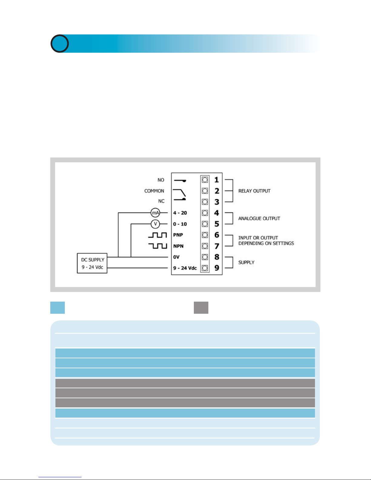
Scale Factor Adjustment: This is a fine tune adjustment on the
signal to compensate for errors introduced by erratic flow or other
system irregularities DENSITY: The flowmeter is fundamentally a
volumetric device but a density figure can be entered here if one
of the mass units are selected. Caution must be used however
as there is no temperature/density correction.
Cut Off: Flow values below this level will be set to zero.
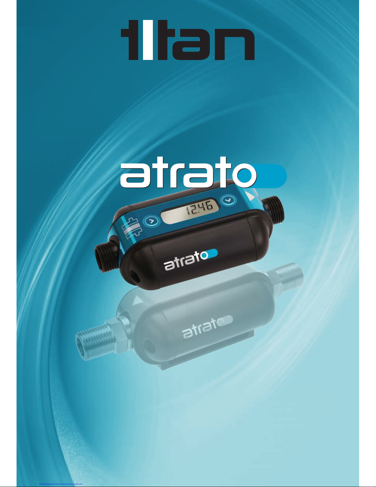
DISPLAY APPEARANCE:
Decrease Total for -ve flow: The meter will not register negative
flow unless this box is checked.
For reverse flow the rate will show a “-“ sign before the rate
and the total will be reduced accordingly. One of the transistor
outputs (PNP or NPN on Pin 6,7 or Pin 8) could be configured to
give a logic level when reverse flow is detected. Once selected
the totaliser will adjust with the negative flow and the NPN and
PNP outputs will give a pulse output in proportion to the reverse
flow seen. The analog pins will not give outputs.
Display Mode: The down arrow selects from the various display
and Metraflow functions.
The options are:-
Rate – The display will show flow rate only.
Total – The display will show total flow only.
Both – The display can be cycled from rate to total using the
left hand button on the Atrato or the left button in the “Real time
window”. The TOTAL can be Reset at any time on the display
model by pressing the Right Hand Button when the Total is being
displayed. Alternatively, a remote input can be used if either pin
6 or pin 7 has been utilised.
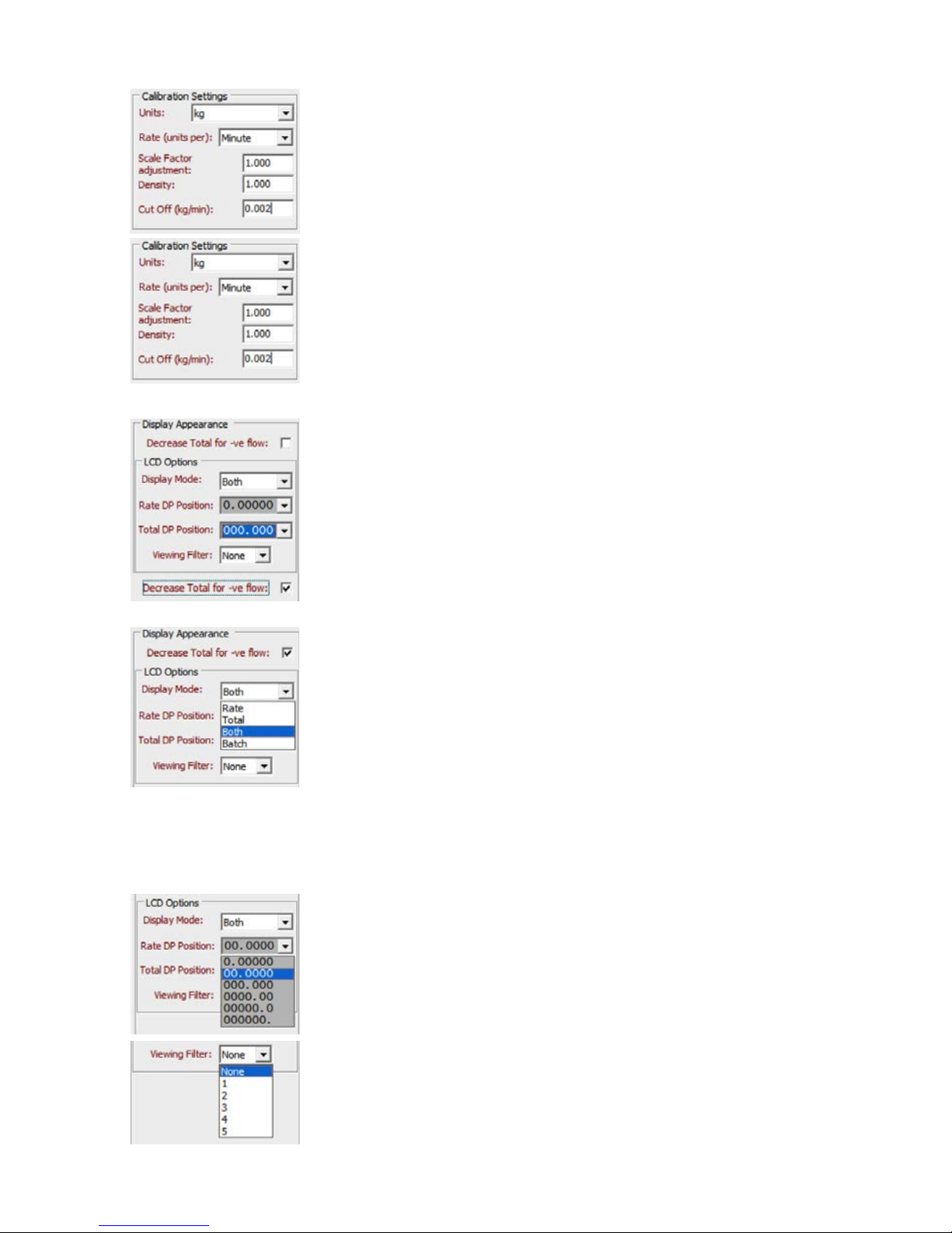
Rate DP Position: Use the drop down menu to choose the
required decimal point position.
Total DP Position: Use the drop down menu to choose the
required decimal point position.
If the decimal point is set too low and the display value exceeds
the setting capacity the display will show ----oF----.
Viewing Filter: This prevents the display, flow switches and
analogue outputs from jittering with irregularities in the flow
from say a peristaltic pump. The increments are arbitrary with
the degree of damping approximately doubling with each level.
Increments go up to 5, which may take up to a minute to stabilise.

10
NOTE: the operation for Pin 6 and Pin 7 are identical with the exception of the
type of transistor output. These instructions are the same for Pin 7 except the
Pin 6 (PNP) would read Pin 7 (NPN).
PIN 6 (PNP):Pin 6 can be configured as either an
output or an input but not both simultaneously. If one
input and one output is required the user must determine
whether they require a NPN or PNP output and use the
appropriate terminal for each action. The options are –
Not used Output Input .
PIN 7 (NPN):Pin 7 can be configured as either an
output or an input but not both simultaneously. If one
input and one output is required the user must determine
whether they require a NPN or PNP output and use the
appropriate terminal for each action. The options are –
Not used Output Input .
EXTERNAL CONNECTIONS
PIN 6 (PNP)/PIN 7 (NPN)
The contents of this box will change depending on the selection made in the External
connection box.
If OUTPUT is selected the check box options are:-
Pulse Single Flow Switch Dual Flow Switch Reverses Flow

11
PULSE: Enter the number of pulses per unit volume
required. This figure can be adjusted to suit the
application and the flow range required from the meter.
The maximum output frequency is 1000 Hz. So care
must be taken to ensure that this pulse rate is not
exceeded.
E.g. 10 L/min at 1000 Hertz equals (1000x60)/10 = 6000 P/L
Therefore 6000 pulses per litre is the maximum resolution
for 10 litres per minute assuming maximum frequency
output. If the meter is being used up to 5 L/Min the pulse
output and so resolution could be doubled to 12000 P/L.
SINGLE FLOW ALARM:
Checking this option opens up input boxes for
THRESHOLD; LATCHING and INVERT
Set the Threshold to the flow value you require the
transistor to operate. The logic of operation can be
adjusted with the INVERT check box (see left).
The Latching box gives the user three options of None;
High Threshold and Low Threshold.
• “None” will cause the alarm to be triggered when the
threshold flow is met. The alarm state will then reset
in accordance with the user set Hysteresis.
• “High Threshold” will cause an alarm signal to Latch
on when flow is seen above the set value
• “Low Threshold” will cause an alarm signal to Latch
on when flow is seen below the set value
Hysteresis (%): This is used when Latching is Set to
NONE to prevent “fluttering” of the alarm signal when
flow is around the threshold level.
LATCHED alarms will remain Active and the Local Display will show “LATCH” until they
are reset. RESET LATCH ALARMS by either a signal Input on one of the other Input/
Output PINS, or by Pressing and Holding the Right Hand Button on the Local Display
on the Flow meter for 3 seconds.
Note the alarm points are driven by the display value on the “flow reading” screen. Any
changes to the filter value of the display will affect the response time of the alarm points
so there are two adjustable parameters to ensure “fluttering” does not happen with
small flow fluctuations - response time and hysteresis.
INVERT – This Check box allows the user to invert the operation of the signal
• Checked – Alarm output logic HIGH
For details see the Alarm logic table or hover mouse over the set point to see the action
of the output with the chosen settings.

12
Checking this will enable a range of flow to be entered.
When the flow is outside/inside of this range the alarm will be
triggered.
The remaining settings in the input box are the same as for
Single Flow alarms.
• When no Latching is chosen the alarm will automatically
reset in proportion to the user set Hysteresis.
• The Latched Alarm can be reset by a signal Input on one
of the other Input/Output PINS, or by Pressing and Holding
the Right Hand Button on the Local Display on the Flow
meter for 3 seconds.
• The INVERT checkbox will reverse the action of the alarm
output. (see the Alarm Logic Table).
DUAL FLOW ALARM:
If INPUT is selected either the Reset Total or Reset Alarm can be operated remotely by
using a switch and resistor to apply a suitable voltage (between 5 and 24 Vdc) to either
Pin 6 or Pin 7 as described on page 13.
This option allows the user to send a signal from the assigned
wire/PIN when reverse flow is seen.
Selecting INVERT will reverse the action of the signal.
REVERSE FLOW:
ALARM LOGIC TABLE
Flow Latching Invert Alarm Action
Alarm Below Threshold Above Threshold
Single None Unticked OFF ON
Single None Ticked ON OFF
Single High Threshold Unticked OFF ON
Single High Threshold Ticked ON OFF
Single Low Threshold Unticked ON OFF
Single Low Threshold Ticked OFF ON
In Range Outside Range
Dual None Unticked OFF ON
Dual None Ticked ON OFF
Dual Out of Range Unticked OFF ON
Dual Out of Range Ticked ON OFF
Forward Flow Reverse Flow
Reverse Flow n/a Unticked OFF ON
Reverse Flow n/a Ticked ON OFF

13
Pin 7 : In input mode, the NPN open collector output is disabled, and the input pin
responds to an external input voltage at TTL levels (VinH ≥2.4V; VinL ≤0.8V). This input
must to be driven by an external voltage supply which can safely be in the range of
zero to 24V. Because of the potential for conflict should the NPN output be activated
accidentally, Titan recommend a resistor so that the source current cannot exceed
5mA. An example circuit is given below:
Example Input to Pin 7
Pin 6 : In input mode, the PNP open collector output is disabled, and the input pin
responds to an external input voltage at TTL levels (VinH ≥2.4V; VinL ≤0.8V). This input
must to be driven by an external voltage supply which can safely be in the full range of
zero to the external supply voltage. Because of the potential for conflict should the PNP
output be activated accidentally, Titan Enterprises Ltd recommend a resistor so that the
sink current cannot exceed 5mA. An example circuit is given below:
Example Input to Pin 6

14
RELAY
RELAY MODE: If the relay is required for a flow switch
check the flow switch box and a further set of options
for set point and hysteresis will appear.
THRESHOLD: Set the required flow rate for the flow
switch. The Reset Offset (%) (Hysteresis) is either
negative or positive depending on whether a falling
or rising alarm is required. The relay has change over
contacts but to reduce power consumption the relay
is off if positive hysteresis is selected and only powers
when the threshold is exceeded. If negative hysteresis
is chosen the relay is on up to the set point. The
increments are preset and can be cycled through using
the + &- buttons. If more than one set point is required
either both transistors must be used or one transistor
and the relay.
ANALOGUE OUTPUTS
ANALOGUE MODE: There are four options on the
drop down menu: Not Used, 4-20mA, 0-5 Volt and
0-10 Volt.
Once the selection has been made you can enter the
low and high flows for the analogue outputs as required.
These are numeric entries in the units and time base
selected in calibration settings.

15
FLOW DETAILS TAB
FLOW RATE: This is the instantaneous flow rate and is updated approximately every
100 milliseconds.
FILTERED This is the filtered flow rate and is identical to the LCD display on the
FLOW flowmeter (if fitted) and the speed of change will depend on the filter
RATE setting. The filter will also affect the response time for the analogue
outputs and the flow switches.
TOTAL: The total liquid passed since the last reset.
PIN 6 & 7: If no selection is made “Not used” will be in the Notes column. See
following text and chart for the display legends.
OR:- When Pin 6 or 7 is set to “Output” and set to “Pulse” this will
display the frequency of the running output and the number of pulses
per litre selected.
OR:- If it is selected to “Output” and set to “Flow switch” the Value
column will show the transistor status either “low” or “high” and the
notes will show the selected switch points.
OR:- If “Output” and “Reverse Flow” are selected the Value column will
show either “low” or “high” depending on forward or reverse flow.
OR:- If “Input” is selected the Value column will show “high” or “low” depending
on the switch condition and “Input Logic level” in the Notes column.
The large display reflects the meter readings showing on the Atrato LCD Display, if fitted
and will mimic that display. The buttons either side have the functions selected on the
‘Configuration’ screen and also work in parallel with the buttons on the Atrato flowmeter
unit itself. The small window below the rate and total display shows various relevant
operational parameters whilst the unit is operating e.g. relay status and frequency
output if these options are selected; and overfill or under fill if in batch mode.

16
The chart below shows the various display messages for various operating functions.
During operation only one message will be shown for each parameter.
Parameter Value Notes Function
Flow rate 2.5000 Litres per minute Units selected in configuration
Filtered flow rate 2.4981 Litres per minute This will lag flow rate
Total 16.95 Litres Total passed since last reset
Pin 6. Off Pin not being used
83.33Hz Output Pulses (2000 per Litre) Frequency output for current flow rate @
2000 pulses/Litre
On Will turn off when rate below 2.7 Flow switch set to 3 L/Min 10% -ve flow.
Off Will turn on when rate above 3.3 Flow switch set to 3 L/Min 10% +ve flow.
Forward Direction of flow Reverse flow tab selected
Low Input logic level Left push button selected will momentarily
show high when remotely operated
Low Input logic level Right push button selected will momentarily
show high when remotely operated
Pin 7. Off Pin not being used
83.33Hz Output Pulses (2000 per Litre) Pulse output selected
On Will turn off when rate below 2.7 Flow switch set to 3 L/Min 10% -ve flow.
Off Will turn on when rate above 3.3 Flow switch set to 3 L/Min 10% +ve flow.
Forward Direction of flow Reverse flow tab selected
High Input logic level Left push button selected will momentarily
show low when remotely operated
High Input logic level Right push button selected will momentarily
show low when remotely operated
Relay Off Relay not being used
On Will turn off when rate below 2.8 Flow switch set to 3 L/Min 10% -ve flow.
Off Will turn on when rate above 3.4 Flow switch set to 3 L/Min 10% +ve flow.

17
PIN 7: The display for “Pin 7” will function the same as “Pin 6” (see page 13).
RELAY: If no function is set for the relay the Value column will show “Off” otherwise
it will display the function and its operating parameters.
BATCHING If Batch is selected in the “Display mode” the relay is automatically
OPTION: assigned to the total display for batching pre-set volumes of liquid. The
preset batch size can be entered in the relay box. This value will be seen
on the LCD display and will count down when the left hand start button is
pressed. The batch can be interrupted by pressing the right hand button,
in the paused state a further press of the right button cancels the batch. If
you wish to continue the batch from the paused state the left hand button
continues the dispense from the point it was interrupted.
If an alternative batch size is required after the unit is disconnected from
the computer pressing both buttons together for 3 seconds will permit
the batch size to be altered by using the right hand key to increment the
digit that is flashing and the left hand button to advance to the next digit.
Holding the left button for 3 seconds enters the selected numbers and the
meter is ready to begin batching. Both buttons can be operated remotely
if required e.g. for remote start/stop signals.
ATRATO ADVANCED USER TAB

Median filter.
This filter removes short term anomalies in the recorded e.g. an air bubble passing
through. It should be used with caution as it is theoretically possible that over use of this
feature could lead to incorrect results in certain circumstances. Under normal operating
conditions the meter returns around 25 results per second and a regular occurrence at
this frequency could be completely ignored thus causing problematic readings.
The filter is a moving window taking the middle number from an odd number of results
selectable between 1 and 21. It is not an average or mean and it is designed to totally
ignore one or more results.
18
PIN protection.
There are 2 possibilities for the PIN protection:-
To use these features it is first necessary to create a PIN. This is a four digit number in
the range 0001 to 9999. Setting a value of 0000 tells the software there is no PIN and
this is how to remove the PIN. After allocating a PIN these check boxes can lock all
of the settings or just the advanced user, including the accumulated total reset. If you
forget your PIN please contact you supplier for the default value. Once entered, all the
setting parameters remain visible. In the ‘Help’ menu, the user can ‘Log On using PIN...’
but the user will be prompted for the PIN prior to making any changes. If the display
version of the meter is being used and the display is set to view totals or rate and total
the left hand button will cycle through the various options.
Rate The display shows units and time base e.g. 1.0 Ltr/min.
Total The display is static with just the volume e.g. 10.3Ltr.

19
SPEED OF SOUND COMPENSATION
The Atrato ultrasonic flowmeter is factory
calibrated on clean water and therefore the
window of calibration is based around the
measured time of flight of the ultrasonic
signal based on the speed of sound of water.
When a fluid is used in the meter that has a
significantly different speed of sound to that
of water, the stable signal may move outside
of the window causing the meter to read
incorrect and unstable time of flight signals. In
this scenario you can compensate by manually
adjusting the measurement window of the
meter in the advanced tab feature for Fluid
Speed of Sound Adjustment. A bar is seen in
the graph indicating whether a strong signal is
being measured. If a fluid has a faster speed of
sound the user can click the FASTER button
to adjust the measurement window a stronger
signal point. A RED graphic is a very poor
signal, ORANGE indicates a weak signal and
GREEN is a Good strong signal
The user then enters a simple scaling factor on the
User Settings tab, to accurately adjust the water
calibration to that of the fluid being measured.
Recorded flow Used flow
0 0
1 1
1 1
2 2
2 2
3 2
0 3
3 3
4 4
4 4
4 4
Recorded and numerical order
2 3 0 0 2 3 2 is used
3 0 3 0 3 3 3 is used
0 3 4 0 3 4 3 is used
The seventh flow in the table above is zero. This could have been a small bubble passing
through the 710 meter which has a 1mm bore which could completely absorb the
ultrasound. The median filter completely ignores this reading and for the zero reading
returns the value of 3 from the results either side. This filter is particularly useful at low
flows where a small dip in value could drop a result below the internal cut off levels.

20
DATALOGGING (not available on all meters)
For general diagnostic purposes it is possible to log the meter performance using the
Data logging Tab function. The logging is not internal to the flowmeter, but stored to the
connected PC and therefore only occurs whilst the PC is connected to the meter.
Simply tick the relevant parameter you wish to log, choose a sensible sampling period
(i.e. for longer data-logging periods choose 10+ second intervals to limit the size of
the file created), and then click the Icon under
Storage File and enter a simple filename (no
spaces) at a location you desire.
Once all is selected correctly the START
LOGGING button will become enabled. Click it to start the datalogging file creation. In
the bottom left corner the samples collected will be listed as the log file builds.
To finish the log file,
simply Click STOP
LOGGING.
This manual suits for next models
3
Table of contents
Other Titan Measuring Instrument manuals