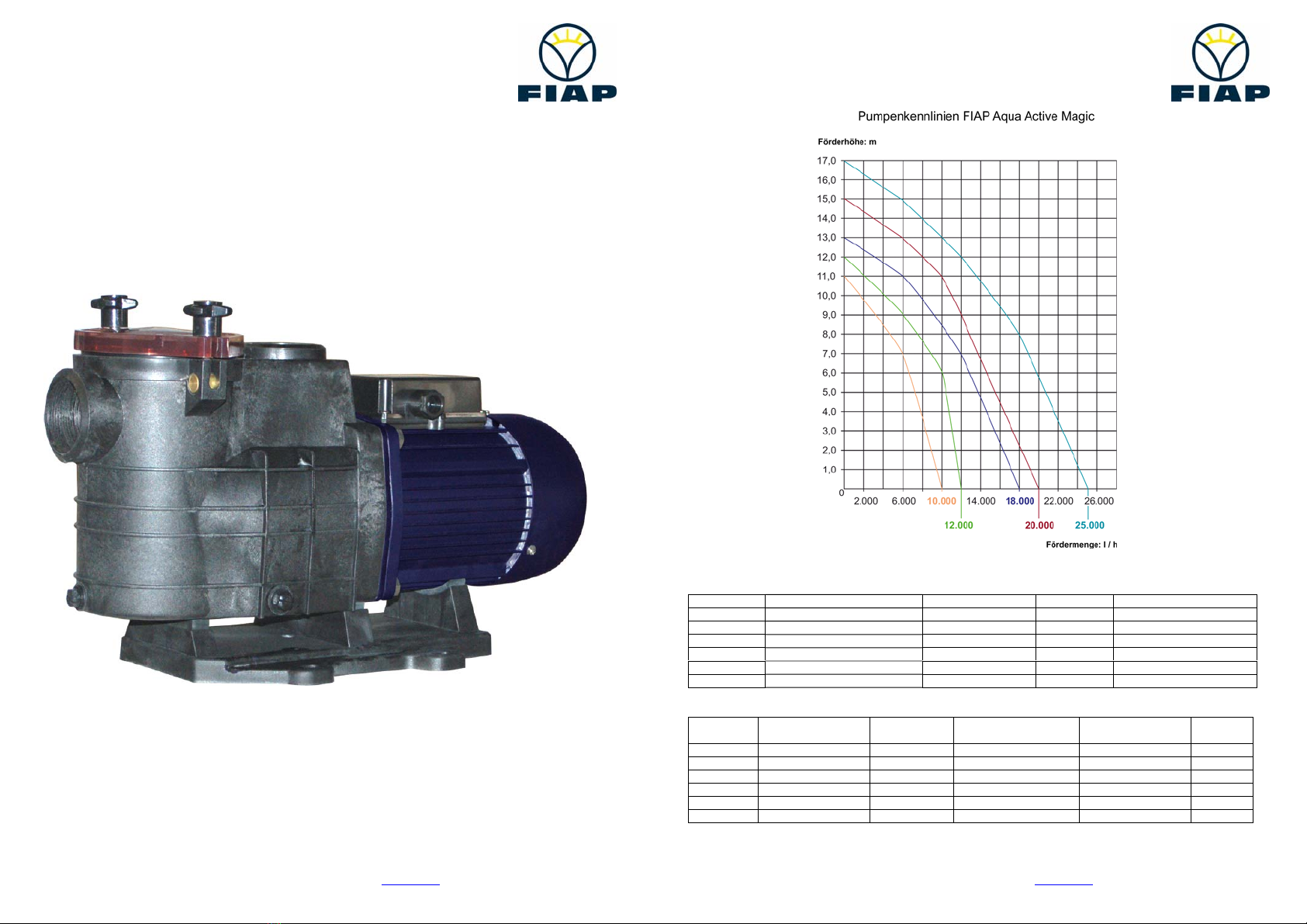
FIAP Aqua Active Magic
Technische Änderungen vorbehalten. Für Druckfehler übernehmen wir keine Haftung. 01/2008 3
FIAP GmbH, Jakob Oswald Str. 16, 92289 Ursensollen
Tel: 09628 9213 0; Fax: 09628 9213 30; www.fiap.com
D
Beschreibung
Die Aqua Active Magic Pumpe ist zur Umwälzung des
Wassers in Garten- und Schwimmteichen einzusetzen. Die
Kunststoffteile sind überwiegend aus Polypropylen PP
hergestellt, Laufrad aus PA 66 GF 30/PC und haben damit
eine hervorragende Korrosionsbeständigkeit gegenüber
dem Wasser und den zur Wasserpflege üblichen
Wasserbehandlungsmitteln. Im Pumpengehäuse sind keine
Verschleißteile enthalten. Damit ist auch das
Pumpengehäuse recyclingfähig.
Die Motorwelle dient gleichzeitig als Pumpenwelle, auf der
das Laufrad befestigt ist. Als Wellendichtung dient eine
Gleitringdichtung, die auf der Laufradnabe aus Kunststoff
sitzt. Hierdurch ist eine sichere Trennung zwischen Wasser
und Elektromotor gegeben. Durch die Blockbauweise hat
die Pumpe einen geringen Platzbedarf. Sie wird durch einen Wechselstrommotor angetrieben. Im
Pumpengehäuse ist ein Sieb integriert, der gröbere Verunreinigungen aus dem Pumpeninneren fernhält.
Aufstellung
Wird die Aqua Active Magic Pumpe im Freien aufgestellt, sollte sie mit einem einfachen Regenschutz
versehen werden. In einem geschlossenen Raum wie z. B. Keller muss unbedingt ein Wasserablauf
vorhanden sein. Ist die Pumpe in einem feuchten Installationsraum aufgestellt, muss für eine wirksame Be-
und Endlüftung gesorgt werden, damit sich kein Kondenswasser bilden kann. Bei kleinen Aufstellungsräumen
kann die natürliche Luftkühlung so gering sein, dass auch hier eine Be- und Entlüftung erforderlich ist, damit
die Umgebungstemperatur von 40° C nicht überschritten wird.
Durch geeignete Maßnahmen ist sicherzustellen, dass Körper- oder Luftschall der Pumpe nicht in
unzulässiger Weise die Umgebung beeinträchtigt.
Es ist darauf zu achten, dass genügend Platzreserve vorhanden ist, damit die Motoreinheit in Richtung
Motorlüfter mind. 90 mm und das Saugsieb nach oben mind. 140 mm ausgebaut werden können.
Zur Befestigung der Pumpe sind ausschließlich Schrauben, Gewinde oder Dübel im Fundament zu
verwenden, um einen Ausbau der Motoreinheit nicht zu blockieren. Saug- und Druckleitung sind
spannungsfrei am Pumpengehäuse anzubringen.
Die Pumpe muß horizontal und trocken aufgestellt werden. Sie kann sowohl unterhalb (Zulaufbetrieb max. 3
m) als auch 2 m oberhalb des Wasserniveaus (Saugbetrieb) montiert werden. Hierbei darf die Saughöhe
zwischen Wasserspiegel und Pumpe (geodätische Höhe) 2 m nicht überschreiten. Die Saughöhe wird durch
Strömungswiderstände in der Saugleitung bei längeren und/oder zu klein bemessenen Rohrleitungen
erheblich herabgesetzt. Es ist auf Dichtigkeit der Saugleitung zu achten, denn bei undichter Saugleitung
saugt die Pumpe schlecht oder gar nicht an. Der Klarsichtdeckel muß ebenfalls dicht aufgeschraubt sein. Die
Saugleitung soll so kurz wie möglich sein. Dadurch verringert sich die Ansaugzeit, die vom Luftvolumen in der
Saugleitung abhängig ist. Bei sehr langen Saugleitungen kann sie bis zu 12 min. betragen. Die Saugleitung
sollte bis zur Pumpe möglichst unter dem Niveau des Wasserspiegels verlegt werden. Es empfiehlt sich, dort,
wo die Pumpe über dem Wasserspiegel installiert wird, in der Saugleitung ein Fußventil einzubauen. Die
Saugleitung kann sich somit beim Stillstand der Pumpe entleeren. Dadurch bleibt die Ansaugzeit kurz z. B.
nach dem Reinigen des Saugsiebes.
Elektroanschluß nur durch einen Fachmann!
Bitte darauf achten, dass in der Elektroinstallation eine Trennvorrichtung vorgesehen ist, die das Abtrennen
vom Netz mit mindestens 3 mm Kontaktöffnung jedes Poles gestattet. Diese Pumpe ist nach Schutzklasse I
gebaut. Die Umgebungstemperatur darf max. 40° C nicht überschreiten.
Pumpen mit Wechselstrommotoren sind serienmäßig mit einem Wicklungsschutzkontakt ausgerüstet.
Die Motoren sind nach ISO Kl. F (Wärmeklasse) gebaut und können außen an den Rippen Temperaturen bis
70° C erreichen.
FIAP Aqua Active Magic
Technische Änderungen vorbehalten. Für Druckfehler übernehmen wir keine Haftung. 01/2008 4
FIAP GmbH, Jakob Oswald Str. 16, 92289 Ursensollen
Tel: 09628 9213 0; Fax: 09628 9213 30; www.fiap.com
Vorsicht: Benutzung der Pumpe ist nur zulässig wenn diese nach DIN/VDE 0100 Teil 702 errichtet ist.
Bitte fragen Sie einen Elektrofachmann!
Der versorgende Stromkreis ist mit einer Fehlerstromschützeinrichtung mit einem Nennfehlerstrom von I ∆n≤30
mA zu schützen.
Die verwendeten Leitungstypen H05RN – F für inneren, H07RN – F für außen, müssen einen
Mindestquerdurchschnitt von 1 mm² haben.
Öffnen des Klemmenkastendeckels:
Mit einem Schraubendreher unbedingt zuerst alle 4 Sicherungsstifte locker hebeln, diese dann von Hand bis
zum Anschlag (etwa 10 mm) nach oben schieben.
Keine Gewalt anwenden, Sicherungsstifte nicht herausreißen!
Mit einem Schraubendreher in den Schlitz fassen und die 4 Nocken nach oben hebeln.
Klemmenkastendeckel senkrecht abheben.
Schließen des Klemmkastendeckels:
Um eine eventuelle Beschädigung der filigranen Dichtlippen zu vermeiden, den Deckel vorsichtig und
rechtwinklig auf das Gehäuse setzen und nach unten drücken.
Erst wenn der Deckel passgenau mit dem Gehäuse verbunden ist, die Sicherungsstifte zum Verrasten
hineindrücken.
Erstinbetriebnahme
Den Gewindering über dem Saugsieb durch Drehen gegen den Uhrzeigersinn lösen und den Klarsichteinsatz
abheben. Die Pumpe langsam mit sauberem Wasser bis zum Sauganschluss füllen. Den Klarsichteinsatz
aufsetzen und darauf achten, dass sich der Runddichtring in der Gehäusenut befindet. Den Gewindering mit
Handkraft anziehen, andernfalls kann die Pumpe nicht oder nicht mit voller Kraft ansaugen. Die Pumpe nicht
trocken laufen lassen! Auch nicht zur Drehrichtungskontrolle!
Achtung: Die ABS-Verklebung, Bundbuchse, benötigen eine längere Aushärtezeit. Inbetriebnahme erst nach
mindestens 12 Stunden möglich.
Zu Beachten:
Pumpe vor Inbetriebnahme, nach längerer Stillstands- bzw. Lagerzeit, - auf Leichtgängigkeit prüfen. Hierzu
einen Schraubendreher in den Schlitz am Motorwellenende (Lüfterseite) stecken und von Hand in
Motordrehrichtung durchdrehen oder, falls erforderlich, die Lüfterhaube entfernen und gleichfalls von Hand
am Lüfterrad in Motordrehrichtung bewegen. Nach Inbetriebnahme auf Dichtigkeit der Gleitringdichtung
achten.
Die Pumpe darf nicht ohne Saugsieb bzw. Saugsieb-Griff (Gefahr des Aufschwimmens vom Saugsieb) in
Betrieb genommen werden, da sie sonst verstopfen oder blockieren könnte.
Bitte darauf achten, dass die eingebauten Absperrvorrichtungen in Saug- und Druckleitung bei Betrieb völlig
geöffnet sind, weil die Pumpe nie bei geschlossenen Absperrorganen laufen darf!
Wartung:
Das Saugsieb muß von Zeit zu Zeit gereinigt werden. Bei verschmutztem oder vollem Sieb geht der
Förderstrom der Pumpe zurück und es findet keine ausreichende Filtration statt.
Reinigen des Saugsiebes:
1. Pumpe ausschalten
2. Absperrorgane schließen
3. Den Gewindering öffnen, Klarsichteinsatz abheben. Saugsieb herausnehmen, reinigen und wieder
einsetzen. Klarsichteinsatz aufsetzen und Gewindering anziehen.
4. Absperrorgane öffnen
5. Pumpe wieder einschalten.
Wird die Pumpe durch den eingewickelten Wicklungsschutzkontakt außer Betrieb gesetzt, ist die Stromzufuhr
zu unterbrechen und zu prüfen, ob sich die Pumpe leicht durchdrehen lässt. Dazu die Motorwelle an der
Lüfterseite mit einem Schraubendreher o. ä. durchdrehen. Ist die Motorwelle schwergängig, muß die Pumpe