Apart from detecting presence of smoke, FIBARO Smoke Sensor has an additional function of informing of exceeding the programmed temperature threshold. The
function is disabled by default in parameter 2 settings.
Excess temperature warning is defined by user in parameter 30 – set to 55°C by default. Excess temperature level can be also signaled by visual indicator glow
(parameter 3) and short beep (parameter 4). Parameter 20 should not be set to 0 because such setting disables temperature measurements.
Malfunction detection
FIBARO Smoke Sensor can automatically detect a malfunction. The device performs a test every 10 seconds. If malfunction is detected (e.g. damaged smoke
chamber) an intermittent sound signal will start and alarm will be sent to the Z-Wave network controller.
Once trouble alarm has been detected, it is recommended to dismount the sensor and:
check the power source (replace battery)
check whether the Smoke Sensor is exposed to direct light
Note: If a malfunction alarm is continually reported, it is recommended to replace FIBARO Smoke Sensor with new one or contact with guarantor if the product
warranty is still valid.
Self-test may be triggered manually:
1. Make sure the device is powered
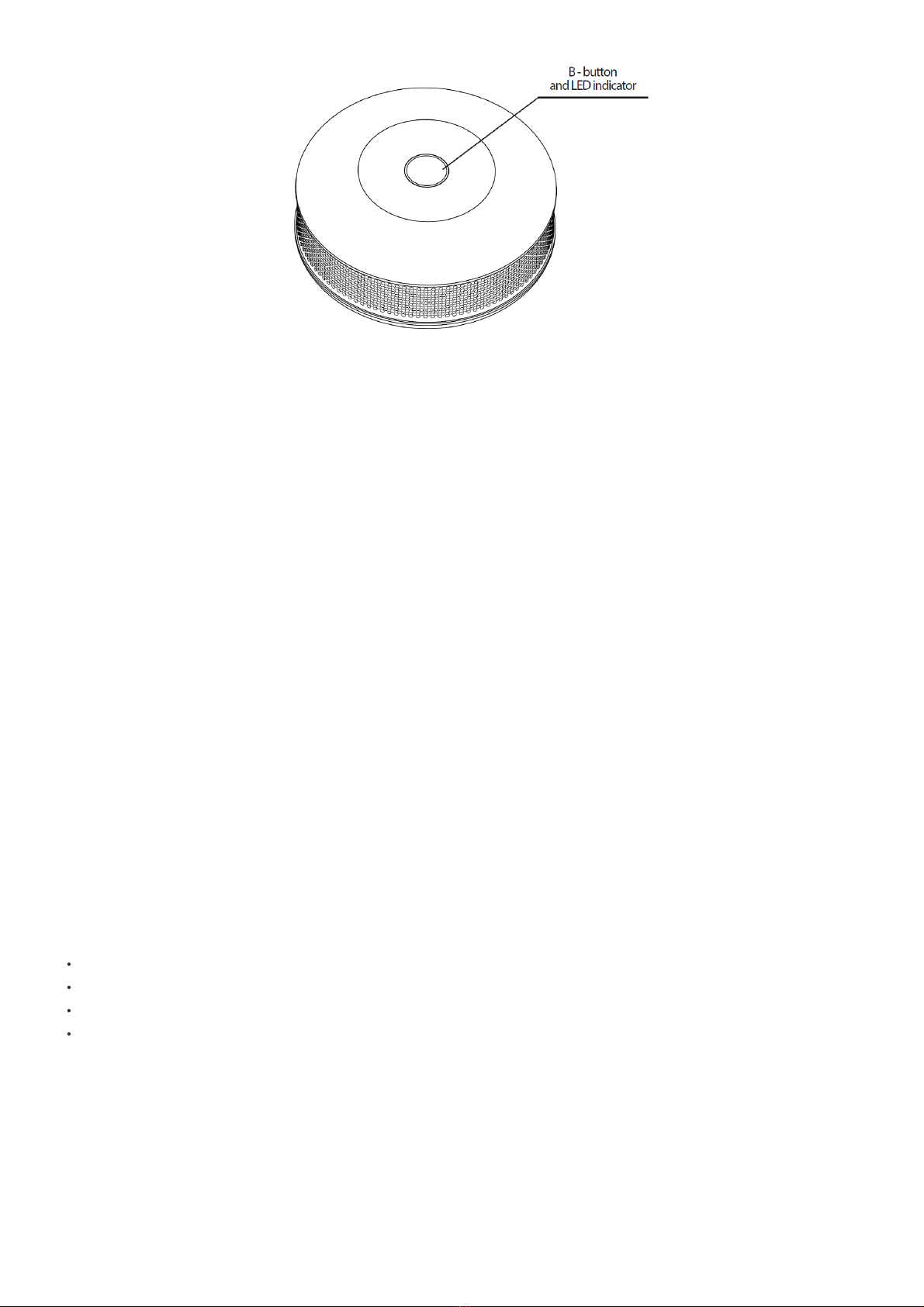
2. Press and hold the B-button
3. The visual indicator will glow white and the short alarm will sound
4. Keep holding the B-button
5. After 3 seconds from the first beep smoke chamber operation will be checked
Triggering fire alarm and beep mean positive result and should occur within 10 seconds. No fire alarm means that the sensor is malfunctioning.
Note: When the self-test is triggered manually the Smoke Sensor sends control command to the Z-Wave network controller. The procedure will be performed at
least as long as the B-button is not released (will be completed in up to 10 seconds after releasing the B-button).
Note: Any service or repair must be carried out by the manufacturer. The expiry date of the device is indicated on its back.
Lack of Z-Wave range detection
When included in the Z-Wave network, FIBARO Smoke Sensor tests the network communication. By default the procedure is performed at each temperature
report depending on parameters 20 and 21 settings. In addition, Z-Wave network communication test is performed during waking up. Lack of the Z-Wave network
communication may be signaled by an intermittent alarm sound and visual indicator blinking violet.
By default sound and visual signals are disabled but you can enable it by changing values of parameters 3 and 4.
Once a FIBARO Smoke Sensor has reported no Z-Wave network communication, it is recommended to wake up the device by clicking the B-button. If it does not
stop the alarm, Z-Wave networks operation and the main controllers operation need to be verified.
FIBARO Smoke Sensor will cancel the Z-Wave network communication alarm once it communicates with the network after manual or automatic wake up.
Communication to a Sleeping device (Wakeup)
This device is battery operated and turned into deep sleep state most of the time to save battery life time. Communication with the device is limited. In order to
communicate with the device, a static controller C is needed in the network. This controller will maintain a mailbox for the battery operated devices and store
commands that can not be received during deep sleep state. Without such a controller, communication may become impossible and/or the battery life time is
significantly decreased.
This device will wakeup regularly and announce the wakeup state by sending out a so called Wakeup Notification. The controller can then empty the mailbox.
Therefore, the device needs to be configured with the desired wakeup interval and the node ID of the controller. If the device was included by a static controller this
controller will usually perform all necessary configurations. The wakeup interval is a tradeoff between maximal battery life time and the desired responses of the
device. To wakeup the device please perform the following action:
Available settings: 0 or 21 600 – 65 535 (in seconds, 6h – 18h)
Default setting: 21 600 (6h)
At each wake up Smoke Sensor communicates with the main controller, updates parameters settings and the software if necessary. The Smoke Sensor will wake
up at defined time interval and will ALWAYS try to communicate with the main controller. After each failed communication attempt, the sensor will retry to establish
connection with the main controller after 60 seconds. After 3 failed attempts, the lack of the Z-Wave range alarm will be triggered. Longer time interval means less
frequent communication and thus a longer battery life. The Z-Wave range alarm will be cancelled automatically, after first successful connection. Change of wake
up interval value does not affect alarms or trouble signals operation.
Setting to 0 disables sending Wake Up Notification frame. Wake up may be still performed manually by a single B-button click or by sending Node Info frame (triple
click the B-button).
Quick trouble shooting
Here are a few hints for network installation if things dont work as expected.
1. Make sure a device is in factory reset state before including. In doubt exclude before include.
2. If inclusion still fails, check if both devices use the same frequency.
3. Remove all dead devices from associations. Otherwise you will see severe delays.
4. Never use sleeping battery devices without a central controller.
5. Dont poll FLIRS devices.
6. Make sure to have enough mains powered device to benefit from the meshing
Association - one device controls an other device
Z-Wave devices control other Z-Wave devices. The relationship between one device controlling another device is called association. In order to control a different
device, the controlling device needs to maintain a list of devices that will receive controlling commands. These lists are called association groups and they are