CTAP-1000
Step 1. Install into Rack
Install RegenTAP-1000 into 19” rack system and you can use “2-slot rack mount guide” if you want.
[ 2-slot rack mount guide is an option accessory ]
Step 2. Ports connections
1. Connect Network Device #1 to Network port A in the RegenTAP-1000 with CAT5 UTP cable.
2. Connect Network Device #2 to Network port B in the RegenTAP-1000 with CAT5 UTP cable.
3. Plug in adapter to AC power and connect adapter jack in the rear part of RegenTAP-1000
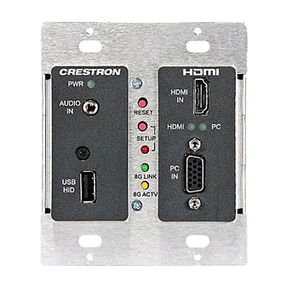
and check LED in front panel as bellows.
• Power status LED(PWR A and PWR B in the front) shows the power is good, it’s dual
power system and should be green at least one of two.
•Packet rate LED (Green color : 10/100 Mbps, Orange color : 1 Gbps)
• Link/Act if LED is blinking Act status which means packet is flowing, if it’s lit continuously
then it’s Link status which means linked but no packet flowing.
4. Connect monitoring device to Monitor port A with CAT5 UTP cable.
5. Connect monitoring device to Monitor port B with CAT5 UTP cable.
[ All port supports MDI/MDIX and auto-negotiation ]
Step 3. Monitoring Device connection
Packets that flow from Network port A to Network port B is duplicated to monitor port A,
Packets that flow from Network port B to Network port A is duplicated to monitor port B,
All monitor ports do not affect to traffic(packet flow) on network line.
You can use those for performance monitoring, error detection,
DDoS detection, hacking detection and protocol analyzing.
Special features
1. Support FCS, PAUSE Packet forwarding
2. Support LLCF ( Link Loss Carry Forward) : LLCF is useful function in the dual network system.
When one link is failed, LLCF function changes the connection from active network to standby
network to keep alive the network.
3. Support Bypass Hardware to keep alive even if its dual power down.
Network Device #1
Network Device#2
CTAP-1000


