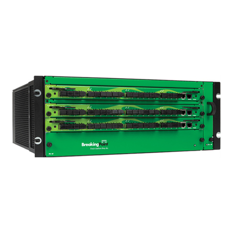
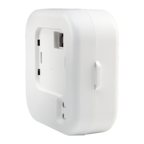
TG-NET Cloud Box M-3 User manual

TG-NET Cloud Box M-3/M-5
User Manual

User Manual
i
Copyright notice
©Copyright 2016 TG-NET Botone Technology CO. Ltd.
Shenzhen TG-NET Botone Technology CO. Ltd. ( short for TG-NET) all right reserved,
and retain all rights to this manual and this declaration.
All content in this manual book shall not be reproduced, copied or used in other ways
without permission. Otherwise TG-NET will have the right to pursue legal responsibilities.
Disclaimer
The content of this manual is based on the existing information, due to product version
upgrades or other reasons, the content is likely to change. TG-NET reserves the right to
modify the contents of the manual without any notice or prompt.
This manual is only used as a guide, TG-NET has made every effort to ensure that the
content is accurate and reliable in the preparation of this manual. But there is no error or
omission in ensuring that the manual is complete. All the information in this manual does not
constitute any express or implied warranty.
Shenzhen TG-NET Botone Technology CO. Ltd.
Tel: +86-755-86963766
Fax: +86-755-86963733
Headquarter: 4F, Building E3, #1001, Zhongshanyuan Road, Nanshan Disctict
City: Shenzhen
Province: Guangdong

User Manual
ii
Contents
1 Notice Before Use ......................................................................................3
2Introduction.................................................................................................4
2.1 Characteristic ....................................................................................4
3Hardware Introduction And Device Connection.................................5
3.1 Hardware Introduction.........................................................................5
3.1.1 Interface...............................................................................5
3.1.2 LED Indicator Light................................................................5
3.2 Device Connection..............................................................................6
3.2.1 Connection Notes..................................................................6
3.2.2 Connection And Application....................................................6
4TCP/IP configuration..................................................................................7
5Login..............................................................................................................9
6WEB Page configuration ...........................................................................9
6.1 Intelligent Statistics............................................................................10
6.1.1 One Key Detection..............................................................10
6.1.2 Device Port Status............................................................... 11
6.1.3 Wireless Online Number ......................................................12
6.2 Function Pool....................................................................................12
6.2.1 Wireless Management.........................................................13
6.2.2 Certification Marketing.........................................................22
6.2.3 Switch Management............................................................25
6.3 Network Topology..............................................................................29
6.3.1 Topology Display.................................................................29
6.3.2 Topology Preservation And Reset.........................................30
6.4 Intranet Scan.....................................................................................30
6.5 System Management ........................................................................31
6.5.1 System Information .............................................................31
6.5.2 System Management...........................................................32

User Manual
3
1 Notes Before Use
Please don’t place device in the vicinity of flammable or conductive materials,
high temperature (such as direct sunlight) or humid environment, or PC
chassis, and check the surrounding appliances and other device is stable or
not.
Please check the cable has no aging phenomenon. To detect and confirm
the AC or DC input voltage value in the range of device allowable, and the
DC polarity is correct or not.
Please use the adapter that comes with the product (indicating the type with
the label)
Please place the device on the smooth plane, don't place items on the
equipment.
Device at work it’s easy to generate heat, should maintain proper space for
heat dissipation to avoid overheating damage. Please keep the slender hole
enclosure ventilation clean, Avoid items from the cooling mouth into the
interior of the device, otherwise it may cause device short-circuit and
damaged or fire. Do not put liquid spilled to the device surface.

User Manual
4
2 Introduction
TG-NET Cloud Box M-3/M-5 (short for M-3/M-5) is TG-NET newly launched a
comprehensive network products that set of wireless management, switch (POE
power management) management, intelligent statistic, network topology in one,
allows the user to easily configure network equipment, network maintenance, and
through wireless certification to achieve advertising marketing.
2.1 Characteristic
For hotels, restaurants, entertainment, business, campus, hospitals and other
places to carry out wireless coverage, typical networking solutions can achieve the
following goals:
Support AP and TG switch centralized management
Support for authenticated users management and control
Support for hybrid authentication, wireless terminal access authentication,
advertising push
Support AP information, AP state, user status information of the unified query
Support AP cross VLAN management
Support VLAN function based SSID features
Support bandwidth speed limit function based STA

User Manual
5
3 Hardware Introduction And Device Connection
3.1 Hardware Introduction
3.1.1 Interface
Interface
Description
LAN1/2/3/4
LAN interface. Can answer the hubs, switches, computers
and other support for local area network equipment.
WAN
WAN interface. Can use Ethernet cable connected to the
uplink network device
USB
USB interface. Can charge the battery for android mobile
phone,and connect USD mini fan.
Reset
Reset key. Long press 6-8 second to loosen again after
the device is powered, you can restore the device to
factory default state.
3.1.2 LED Indicator Light
Indicator light
Mode
Status
PWR
N/A
The power indicator light,red
light has been on when the
device is power on.
SYS
N/A
SYS light in the process of
device boot,and go out after
full boot.
LAN1~LAN4
100M
bps
Green light indicates that the
connection is established,
flashing indicates data
transmission.
WAN
100M
bps
Green light indicates that the
connection is established,
flashing indicates data
transmission.

User Manual
6
3.2 Device Connection
3.2.1 Connection Notes
Connection device with the computer, network hub or switch cable length can
not be greater than 100 meters
Please put the wireless device in the central area to maximize the wireless
coverage area
3.2.2 Connection and Application
Typical networking as shown above. Router connect down the core switch and
POE switch, M-3/M-5 side hang in switch,theAP through POE power supply,
terminal associated wireless to carry on the internet.
1 M-3/M-5 can centralized management switch and AP, configure and issued
them.
2 M-3/M-5 access will not have an impact on the cable terminal. Wireless
terminal access network,and open authentication on M-3/M-5 can achieve the
purpose of advertising marketing,at the same time can control the Internet
behavior of the wireless terminal.

User Manual
7
4 TCP/IP Configuration
Take the Windows system as an example,describes the login TCP/IP need
M-3/M-5 configuration
1 Click on the bottom left corner of the start menu, enter 【The control
panel-network connection】, or right click on the network icon in the lower right
corner of the desktop, open the "network connection" window。
2 In the "network connection" window,right click the "local connection",then left
click to select the "properties" option.
3 In the pop-up window,double-click the left mouse button "Protocol Version
Internet 4(TCP/IPv4)".

User Manual
8
4 In the pop-up window,click the left mouse button the "use the following IP
address(S)",then enter your desired IP address in "IP address". IP address range
is "192.168.255.(2-253)". does not need to set the subnet mask,The bar will be
automatically generated after you enter the IP address. The remaining options bar
does not need to fill in. The left mouse button click the lower right corner of the "OK"
button.
M-3/M-5 default IP address is 192.168.255.254, User name and password is:
admin/admin.
Tips:
If the computer is equipped with multiple network cards ,network
connection items will display a number of "local connection" menu.

User Manual
9
5 Login
Open IE or another browser (IE9.0 or above, Firefox, Google and etc are
recommended). Enter http://192.168.255.254 in the address bar and press Enter.
Enter the username and password (admin/admin) on the page displayed.
Tips:
The default password is printed on the device box bottom label.
When you configuring the web page,please don’t cut off the power supply,
otherwise it may cause damage to the device.
6 WEB Page Configuration
After logging in to M-3/M-5,the first to see is the intelligent statistics page.

User Manual
10
The bottom of the page for the first level menu,It’s mainly includes three first
level Icon. The three first level icons are intelligent statistics, function pool, system
management.
The middle of the page for the intelligent statistical features display area,this
area includes a key detection, device port status, and the number of wireless online.
The upper right corner of the page icon to exit the shortcut button,click the
icon to exit the web configuration interface at any time.
6.1.1 Intelligent Statistics
Intelligent statistics contains detection, the device port status, the number of
wireless online.
6.1.2 One Key Detection
TG-NET M-3/M-5 original and 360-type one key detection. It can quickly scan
the network device running state, and gives the solution of the existing problems,
optimization suggestions. Mainly in the network of TG devices in the hardware stable,
stable configuration, network stability, network security and other aspects of a
comprehensive test,and according to the category of diagnosis,the detection results
were displayed to each test item. Click the "One Key Detection button", it can be
intelligent diagnosis. Detection is completed, if the diagnosis is no exception, then the
display is "normal". If there is an exception in the diagnosis, it will prompt the
existence of "anomalies", and display the abnormal diagnosis results.

User Manual
11
Click to have an exception detection item,you can view the details of the
diagnosis. As shown below,Users can handle the proposed operation in accordance
with the details of the diagnosis, improve network security.
6.1.2 Device port status
Port description of device port status as shown below:

User Manual
12
6.1.3 Wireless Online Number
Click the "Wireless online number ", as shown below. Click the date below to
view the 24 hours of the day the number of Online, click the "save" button in the
upper right corner to save the image.
6.2 Function Pool
Click “Function Pool”into the basic functions management interface.
This interface has three functional modules, including wireless management, switch
management and router management.

User Manual
13
6.2.1 Wireless Management
Click “WLAN”icon to enter the following interface:
WLAN module is mainly used for managing AP in Intranet, unified configuration
issued, Achieve certification, advertising push service, AP monitor statistics, terminal
monitoring statistics, and etc.
6.2.1.1 Quick Guide
1 Click “Quick Guide”on the left menu bar, start configuration.
2 Setting AP key management, it is recommended to keep the default
configuration. (AP management key matches in order to be AC control when
AC/AP default management are admin)
3 Configure the default AP template AP manage, configure AP template basic
information about the SSID.

User Manual
14
4 After setting, click the "Apply" button to complete the configuration.
6.2.1.2 Monitoring Statistics
Monitoring statistics including AP information table, AP status table and the
user status table, as shown below.

User Manual
15
6.2.1.3 Function Management
Click on “Function management”button, enter the function management
configuration page. Function management is mainly used for settingAP management
key, enable wireless roaming, enable AP local authentication and configuring AP
broadcast suppression.
AP management key: Authentication mechanism for communication between
M-3/M-5 and AP, AP can only be managed by the M-3/M-5 that matches its
management key, key does not match theAP will not be M-3/M-5 management.
Wireless roaming:Achieve activeAP roaming, roaming detection cycle enabled
by default.
AP local authentication: Achieve the AP local forwarding mode switches, after
opening,AP local forward user need to verify in order to access the Internet.
AP broadcast suppression: Configuring AP suppression number of broadcast
packets per second, the number "0" setting does not inhibit, the default is 10
pps.
6.2.1.4 DHCP Configuration
M-3/M-5 is provided with DHCP Server, LAN users can be on-demand IP
address. Click “DHCP Configuration”, enter DHCP address pool configuration page,
as shown below:

User Manual
16
DHCP server: If you need to use the DHCP function of M-3/M-5, then check
“Enable”; If you use the front-end router or other DHCP server, the check is “Disable”.
DHCP functional mode: This module is divided into user mode and common
mode. User mode only for the SSID based wireless terminal distribution IP address;
Common mode for the gateway based on the wired, wireless terminal distribution IP
address.
After the configuration is complete, click "apply" to come into effect.
Tips:
In common mode, IP in the IP address pool must follow superior routing in the
same network segment in order to access the Internet.
DHCP IP address pool can assign up to 2048, to address the border, should
be combined with the network, use a router or other larger capacity DHCP
pool, maximum number of concurrent 100.
6.2.1.5 AP Management
Click on the "AP Management" button, enter the page shown below, is used to
manage theAP distributed configuration and maintenance.

User Manual
17
AP Templates
This page is used to create, delete, modify the AP templates. Maximum 512
template.
Tips:
When the AP and M-3/M-5 key matching, after the access to the AP, M-3/M-5
automatically to AP issued by default template configuration, the default
template “Defaults”can not be deleted, only support to modify the
configuration information.
Click on the “actions”column of “details”button, can view and modify the
template details. Click “add”button, can add a newAP template.

User Manual
18
On this page you can set the SSID forwarding mode. There are two forwarding
modes, one is to centralized forwarding, the other is local forwarding. Among them, local
forward is a wireless business data directly from the switch to the router to forward out, not
through the M-3/M-5 forwarding, as figure(1) below shows; Centralized forwarding is
wireless business data redirected to the M-3/M-5 first, and then forwarded by the M-3/M-5,
as figure(2) below shows.
Figure (1) local forward Figure(2) centralized forwarding
Tips:
When the forwarding mode is local forward, if you need to configure
authentication, you can enable the AP local authentication function in
“Function management”.
ADD AP template

User Manual
19
Click on “add”button, enter the page of addAP template configure, as the shown
below:
Items must be configured: template name, login name, login password, SSID name,
user limit number; the rest is optional, if no special requirements are suggested using the
default configuration.
Tips:
The configuration of the channel state code is based on the legitimate
configuration of your country;
If you need to encrypt the SSID, Proposed to choose the use of
WPA/WPA2-PSK security model and the combination of AES/TKIP encryption
algorithm, encryption security is above the average, the terminal
compatibility is good.
After the configuration is complete, click "apply" to come into effect.
This manual suits for next models
1
Table of contents

