Fiber Tronix FT-FOTR-16VD-ST-S User manual

v1.0 4/5/11
1
INSTALLATION MANUAL
FT-FOTR-16VD-ST-S
16-Channel Digital Duplex
Baseband Video Transmitter and Receiver
With Reverse Data Transmission
for PTZ Cameras

v1.0 4/5/11
2
PACKAGE CONTENTS
This package contains:
One each FT-FOTR-16VD-ST-S 16-channel baseband video transmitter and receiver
Two 5VDC power supplies
One installation manual
PRODUCT DESCRIPTION
The FT-FOTR-16VD-ST-S fiber optic transmitter/receiver supports the transmission of sixteen
baseband video channels and a single reverse data signal over one strand of single-mode fiber
optic cable. This product is compatible with all NTSC and PAL video signals. Power, optical signal,
video signal and data signal are easily inspected through LED indicators directly on the units. The
transmitter and receiver combination supports transmission distances for optical loss budgets of
less than 18 dB.
SPECIFICATIONS
FT-FOTR-16VD-ST-S
Specifications (Typical)
1. Optical Wavelength
1310nm / 1550nm
2. Fiber Type
Single-mode 9/125µm
3. Maximum Link Distance
12.5 miles
4. Connector
Simplex ST
5. Acceptable Loss Budget
18 dB
6. Number of Video Inputs
16
7. Video Connector
BNC Female
8. Transmitter Input Impedance
75Ω unbalanced
9. Receiver Output Impedance
75Ω unbalanced
10. Video Bandwidth per Channel
0Hz –6.5MHz
11. Video SNR
>60 dB
12. Differential Gain
<1%
13. Differential Phase
<1°
14. Tilt
<1%
15. Data Rate
0 –300Kbps
16. Data Connector
Terminal Block
17. Data Interface
RS485, RS422 or RS232
18. Baud Rate Per Channel
0 –100Kbps
19. Bit Error Rate
<10-9
20. Power Supply
5VDC
21. Power Consumption
<10W
22. Operating Relative Humidity
0 –95% non-condensing
23. Operating Temperature
14F –122F
24. Dimensions
9.1”x8.2”x2.2” per unit
25. Weight
2.6 lb. per unit

v1.0 4/5/11
3
INSTALLATION AND OPERATION
CAUTION: To reduce the risk of electrical shock do not remove the cover or back of this
unit. No user serviceable parts are inside.
CAUTION: To prevent electric shocks and risk of fire hazards, do not use other than
specified power source.
1. UNPACKING and HANDLING
Each unit is shipped assembled and factory tested.
Ensure that all accessories are removed from the container before discarding packing material
2. MECHANICAL INSPECTION
Inspect the front and rear of the equipment for shipping damage. Make sure the equipment is
clean, and no connectors are broken, damaged, or loose. If equipment appears to be damaged
or defective please contact your distributor or Fibertronix at 1-610-429-1511 for assistance.
3. WIRING CONNECTIONS
Transmitter Front and Rear Panels
Data Tx
Data Rx
Power
Optical
Digital Video Optical System
678
14 15 16
5
13
123 4
910 11 12
Video Signal Indicators
POWER CH1
CH9 CH10 CH11 CH14CH12 CH13 CH15 CH16
CH2 CH3 CH4 CH5 CH6 CH7 CH8
OPTICAL
Optical port
(ST/PC)
Power Input
(DC5V)Video Input 1-16 ch
A B
Data
G
Data connector
(Terminal Block)
This symbol is intended to alert the user to the presence of important operating and
maintenance (servicing) instructions.
This symbol is intended to alert the user to the presence of “dangerous voltage” within the
product’s enclosure that may be of sufficient magnitude to constitute a risk of electrical
shock.

v1.0 4/5/11
4
Receiver Front and Rear Panels
Data Tx
Data Rx
Power
Optical
Digital Video Optical System
678
14 15 16
5
13
123 4
910 11 12
Video Signal Indicators
POWER CH1
CH9 CH10 CH11 CH14CH12 CH13 CH15 CH16
CH2 CH3 CH4 CH5 CH6 CH7 CH8
OPTICAL
Optical port
(ST/PC)
Power Input
(DC5V)Video Output 1-16 ch
BG
A
Data
Data connector
(Terminal Block)
Terminal Block
A: Data Output +
B: Data Output –
G: Ground Connection
a. Plug the included power supplies in a 120VAC outlet. Each power supply’s DC output
adaptor connects respectively to the power input of the transmitter and receiver.
b. Connect the transmitter and receiver’s optical connectors with an ST/PC patch cable.
The transmitter and receiver’s Link Indicator Lights will indicate optical signals are
transmitted and received normally.
c. Connect the video source (e.g., camera) to the transmitter’s video input port using
quality 75Ω coaxial cable with BNC connectors.
d. Connect the video monitor to the receiver’s video output port using quality 75Ω coaxial
cable with BNC connectors.
e. Connect the data ports using the RS485 terminal block. Be sure the wiring
configurations are consistent with the diagram above for the transmitter and receiver
as well as the PTZ camera.
f. Indicator lights:
Power LEDs display power status. A normal display indicates the input
power supply is correct. An irregular display indicates the wrong input power
or a problem with the unit’s circuits.
Optical LEDs display whether the optical signals are being transmitted and
received correctly.
Video Signal LEDs indicate the video status
Data TX and Data RX LEDs respectively display data output and data input
status.
A B G
Data
RS485

v1.0 4/5/11
5
4. SPECIAL ATTENTION
a. Only use the power supplies included with these units. The use of other power supplies
may damage the transmitter and/or receiver and void the warranty.
b. The loss of optical fiber should be less than 18 dB. Any loss greater than 18 dB will
compromise the receiver’s ability to get the optical signals from the transmitter.
c. Adhere to the equipment’s in-door operating temperature and humidity specifications.
Failure to do so may damage the equipment and void the warranty.
5. TROUBLESHOOTING
a. No picture after applying power –(i) check all connectors and cables are securely
connected to the video source, monitor, transmitter and receiver; (ii) ensure all power
supplies are providing the correct voltage and current.
b. No image or poor image quality –determine if the optical signal loss is greater than 18
dB.
c. The picture has ripples –(i) check to see if the camera’s power supply is experiencing
AC ripple, if so a filter may be required; (ii) determine if the monitor is faulty; (iii)
determine if other peripheral equipment is causing ripple and if so make the necessary
adjustments.
d. The picture background continuously changes color –a fluorescent lamp’s magnetic
field may cause color roll, therefore, reduce the number of fluorescent lamps or
increase the distance between the camera and the lamps.
e. The picture appears smeared –(i) the camera’s power supply voltage level may be
unstable, therefore, try another power supply; (ii) ensure the camera and/or monitor
cables are correctly connected and/or the cables are of the correct impedance.
f. Other interference may require a Fibertronix ground loop isolation filter.
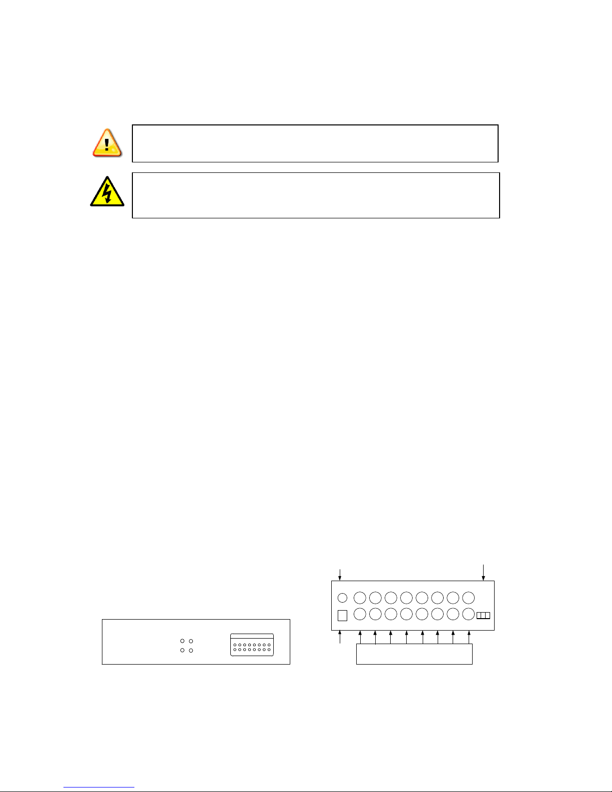
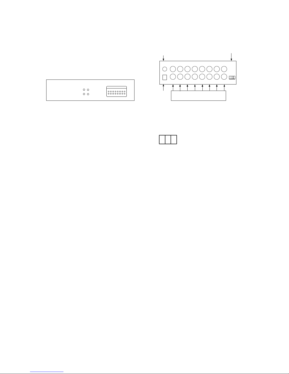
g. Data communications are not working –(i) ensure all cables and connectors are
secured and (ii) ensure all terminal block connections are consistent as specified in the
wiring diagram for the transmitter and receiver and the PTZ camera.
h. Additional troubleshooting assistance can be found on-line at www.fibertronix.com in
addition to support from Fibertronix sales engineers at 1-610-429-1511.
Table of contents
Popular Transceiver manuals by other brands

ADTRAN
ADTRAN SFP+ Combo PON D1 OLT quick start

Park Air Systems
Park Air Systems T6TR User documentation

Sael
Sael RRF Installation and operating manual

Yaesu
Yaesu FTdx5000 Series operating manual

Vertex Standard
Vertex Standard VX-146 operating manual

Williams Sound
Williams Sound Digi-Wave 300 Series user manual