Fibersystem 21-180 User manual
Fiberoptic G.703 Converter
21-180
Technicalmanual
FS18134-Technical-Manual-21-180-R2
1

About this manual
About the contents of this manual
The information in this document may be changed at any time without notice.
Table of Contents
About the contents of this manual 2
Table of Contents 2
Version and revision history. 3
Revision history for product: 3
Revision history for this document. 3
Functional 4
Fiber Optic G.703 Codirectional 4
Applications 4
Features 6
Fiberoptic and data transfer protocol 6
G.703 – Codir 6
Power Supply. 6
Environmental conditions 6
CE compliance 6
Mechanical 6
EMC compliance 6
Insulation 7
Physical size and Weight 7
Unpacking. 8
Product 21-180 consists of: 8
Serial number. 9
Front Panel. 9
Back Panel. 9
G.703 Codir Port 11
Fiber Optic Port. 11
Functional earth/ground, FE. 12
Signal ground - Protective earth/ground. 12
Normal use 14
Config rotary switch 14
External clock 15
Fiber clock. 15
Internal clock – “Master mode” 15
Power on. 16
LED-status. 16
CE - mark 18
2

3
Version and revision history.
Revision history for product:
Revision R0.
Product released for serial production. 2006-06-26.
Revision history for this document.
Revision AK0.
2006-06-22, AnNy, document created. Revision
R0. 2006-06-26, AnNy, document released.
Revision R1.
2006-06-26, AnNy, applications updated.
Revision R2
2018-03-12, MiLa, document corrected.
Document properties.
Last saved: 12/3/2018 13:05:00
Filename: FS18133 Technical Manual
21-170 R4
Author.
Created by Anders Nyström.
Last saved by Mikael Larsson

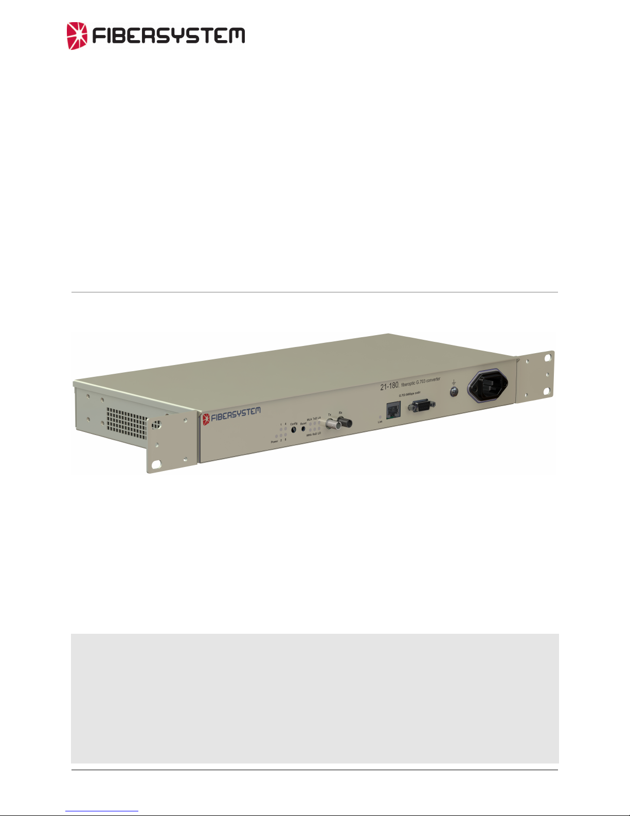
General description
Functional
The 21-180, Fiberoptic G.703 converter is intended to extend distance and galvanic
isolate the teleprotection equipment for substations connection to telecom network.
Fiber Optic G.703 Codirectional
The ITU-standard “G.703 64kbit/s codirectional interface” describes a galvanic
interface. This interface is for example commonly used by teleprotection equipment
for connection to telecom multiplexers.
The codirectional interface is transferred at one balanced pair for each direction.
21-180
The 21-180 converts the codirectional interface signals to a proprietary fiber optic
protocol.
Applications
The fiberoptic port of the ABB REL55x/56x , Line Differential Protection
Terminals, is directly connected to the fiberoptic port of 21-180. The 21-180 Codir-
port is then connected to a 2048kbps G.703 E1 multiplexer.
64kbps
fiber optic
interface
60-00-2721
Telecom
Network
REL 55x / 56x
REL 55x / 56x
E1 Multiplexer
E1 Multiplexer
21-180
64kbps galvanic interface
60-00-3521
G.703
64kbps codir
fiber optic
G.703
64kbps codir
galvanic
G.703
64kbps codir
galvanic
4

Or connect to another Fibersystem product using the same fiber optic protocol.
5

6
Features
Fiberoptic and data transfer protocol
Data speed/protocol Fibersystem proprietary protocol.
Optical data
Wavelength 820nm
Fiber optical connector ST
Optical System budget 13dB with multimode fiber,
(62.5/125 um)
9dB with multimode fiber,
(50/125 um)
Typical distance 2km (6dB systemmargin for 62.5/125
and 3dB margin for 50/125).
G.703 – Codir
Interface 9-pin female D-sub or RJ45. 120Ohm.
Protocol G.703, 64 kbit/s.
Power Supply.
48V DC to 250V DC, +20%
110V AC to 230V AC, 50Hz, +20%.
AC connector IEC 320, 3 pin.
Power consumption <20W.
Environmental conditions
Operating temperature range -25 to +70 °C.
Storage temperature range -40 to +85 °C.
Relative humidity operating 5 to 95%.
Relative humidity storage 5 to 95% non condensing.
CE compliance
Immunity EN 61000-6-2
Emission EN 61000-6-4
LVD EN 50178, RIV = 250V OVC = III
Mechanical
Vibration IEC 60255-21-1 Class 2
Shock IEC 60255-21-2 Class 2
Sesmic IEC 60255-21-3 Class 2
EMC compliance
ESD IEC 60255-22-2 Class 3, contact 6kV, air 8kV.
Radiated IEC 60255-22-3 / IEEE/ANSI C37.90.2; 35V/m
Burst Power IEC 60255-22-1 Class III
Burst Communication IEC 60255-22-1 Class II; 0,5kV diff, 1kV common mode
Fast transient Power IEC 60255-22-4 Class IV
Fast transient Communication IEC 60255-22-4 Class II; 1kV

7
Insulation
Dielectric test IEC 60-255-5, 2,0kV 1min
Impulse voltage test IEC 60255 / EN 50178 5kV / 6kV
Insulation resistance IEC 60255-5; >100MOhm at 500VDC
Physical size and Weight
The unit can be to be mounted in a 19” rack.
By adjusting, the rack mount brackets, the unit can also be mounted on a wall or
similar.
Height 45 mm
Width 483 mm (380 mm without rack mount brackets).
Depth 173 mm (from front to back, connectors excluded).
Weight 3 kg

Unpacking.
Check that the packing material has no damage. If damages are discovered on packing
material, contact your shipping company, before unpacking.
The delivered product consists of several parts. Check that all parts are present
according to the list below, and have no damage.
Product 21-180 consists of:
Quantity Part number Description
1 1 21-180 Fo modem G.703 64kbps
(Part number includes all parts in this list).
2 2 60-00-5387 Rack Mounting Bracket
3 8 50-65-1673 Screw, MFX-H M3x5 FZB
4 1 50-65-0106 Power cord, 1.8m European connector.
5 4 50-65-5030 Rubber feet
6 1 90-20-0112 This manual
21-180, (Part number includes all parts in list above).
Power cord.
2 Rack mounting
brackets
8 screws for rack
mounting brackets
4 Rubber fee
t
8

Installation.
Serial number.
The products serial number is the best way for Fibersystem to identify the product.
If the serial number is not noted on your delivery notes, please add the serial number
to your own product documentation. This will be useful at future contact with
Fibersystem.
9
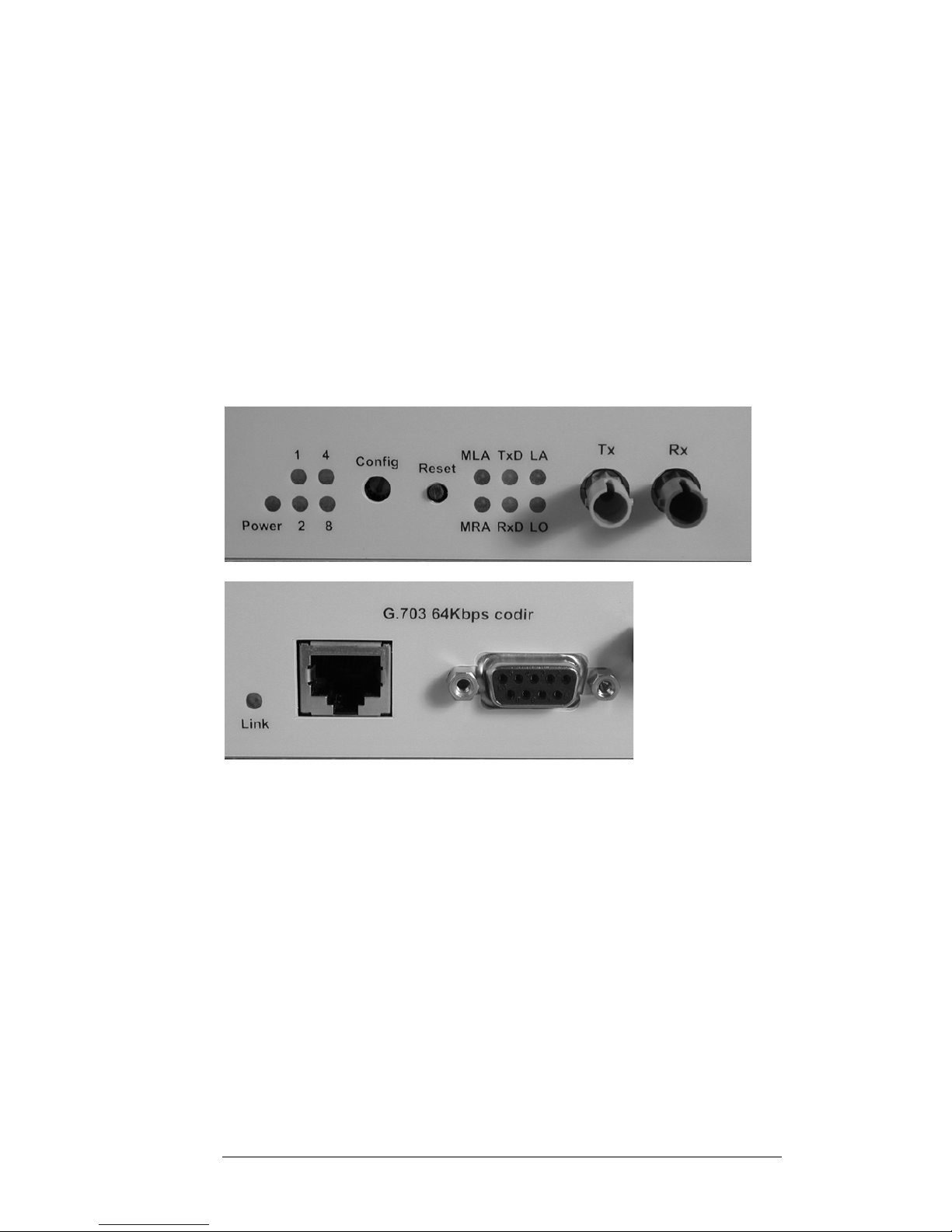
Front Panel.
Serial number
S/N
Fiber Optic Port
Functional
earth/ground
Power Supply
IEC 320
connector
G.703 Codir por
t
Status LEDs
and configuration
Back Panel.
There are no connections or indications on the back panel.
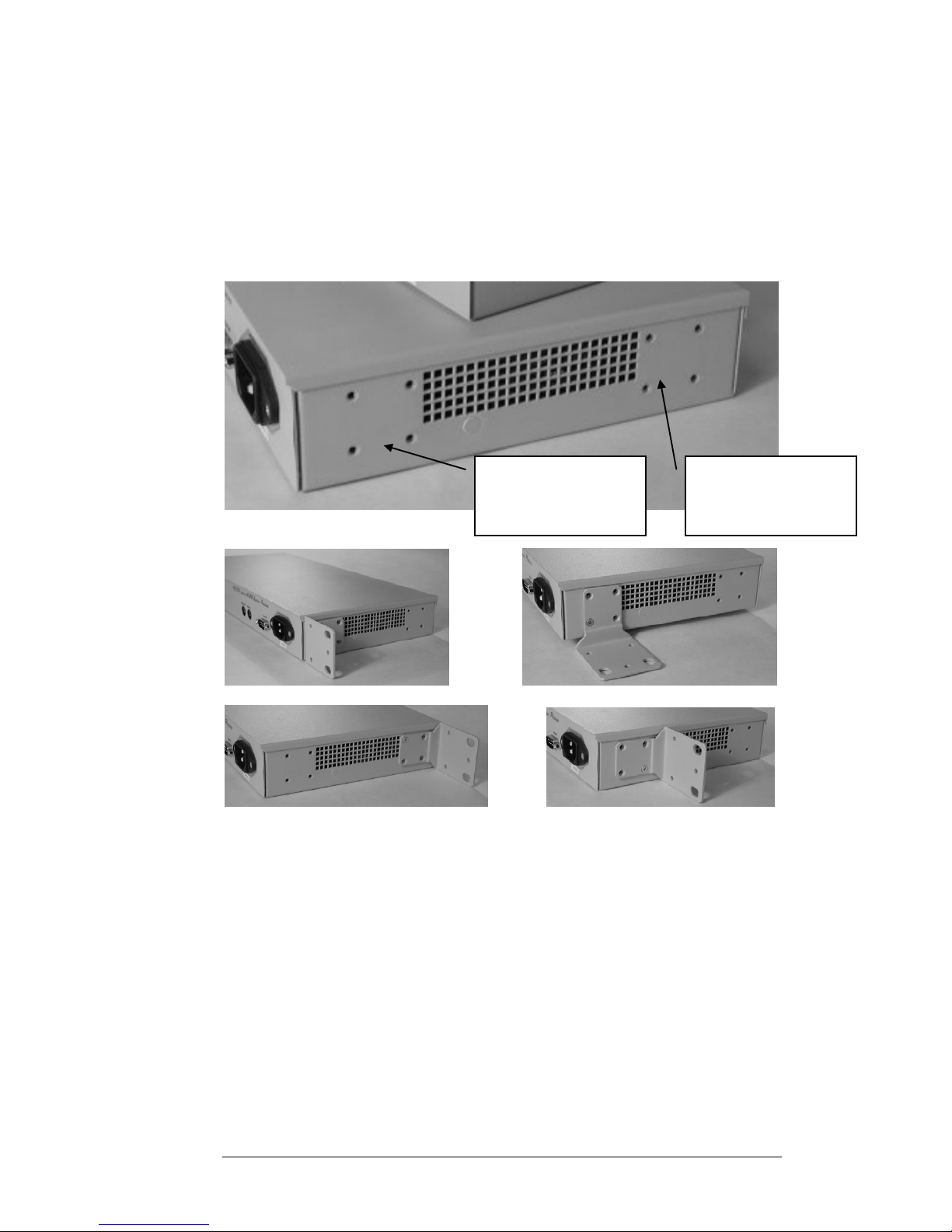
Mounting
Before mounting check if 21-180 must be configured internally. See later in this
chapter under section “Signal ground - Protective earth/ground”.
The products can be used stand alone, rack mounted or attached with screws to wall
or similar.
The rack brackets have two alternative places on each side of the unit and the
brackets can be rotated for alternative positions.
Alternative rack
bracket mounting
positions
Alternative rack
bracket mounting
positions
10
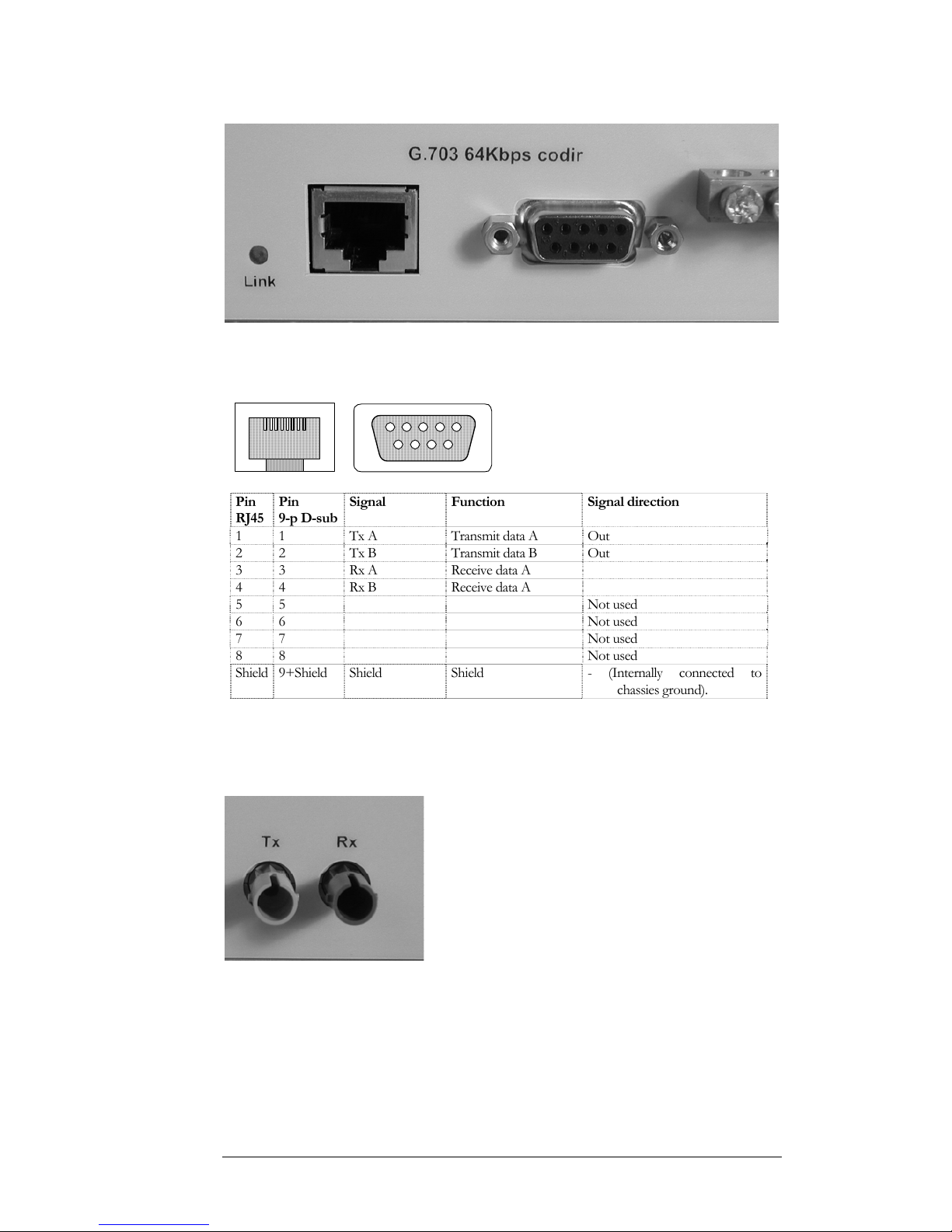
G.703 Codir Port
The Codir interface uses one balanced pair for each direction of transmission.
Impedance 120 Ohm.
The RJ45 connector and the 9-pin D-sub connector are connected in parallel.
81
96
51
Pin
RJ45
Pin
9-p D-sub
Signal Function Signal direction
1 1 Tx A Transmit data A Out
2 2 Tx B Transmit data B Out
3 3 Rx A Receive data A
4 4 Rx B Receive data A
5 5 Not used
6 6 Not used
7 7 Not used
8 8 Not used
Shield 9+Shield Shield Shield - (Internally connected to
chassies ground).
Always use cables with a good shield. For example S/FTP, (twisted pairs with foil
shielding around each pair and a braid shielding around cable).
Fiber Optic Port.
The fiber optic connector is of ST type.
Confirm that the attenuation of the fiber optic cable, including splices and patch
cables, doesn’t exceed the system budget. Don’t forget to add a safety margin.
Minimum safety margin is 3dB.
Make sure that the local fiber optic transmitter, marked Tx, is connected to the
remote units fiber optic receiver, marked Rx. And local Rx shall be connected to
remote Tx.
11

Functional earth/ground, FE.
To the left of the IEC 320 power supply connector, a reference ground/earth screws
are available.
Protective earth/ground, PE, shall always be connected to the IEC 320 power supply
connector.
Signal ground - Protective earth/ground.
Factoty setting for relation between Signal ground and Protective earth/ground I
“Soft”. Signal ground is connected to PE with a resistor, (100kOhm), in parallel with a
condensator, (100nF).
A direct connection between Signal ground and PE can be strapped.
To do this the 21-180 must then be opened.
Disconnect power.
Four screws at the backpanel shall be removed. Puch top lid towards backpanel.
Lift top lid.
P2
12

P2
To connect Signal ground and Protective ground directly connect the terminals of P2
with strap.
13

Configuration
Normal use
Normally no configuration is needed!
When two 21-180 are connected back-to-back, (G.703 Codir ports connected to each
other), one of the 21-180 should be set to “Internal Clock”.
Config rotary switch
Configuration switc
h
The rotary switch has 16 positions, (HEX-switch).
At position 0 the switch’s arrow, visible through the adjusting hole, points straight
down.
All configuration is done by setting the position of the “Config” rotary switch on the
frontpanel. The “Config”-switch is operated with a small screwdriver. The switch has
16 positions. Every switch position is presented by the four LEDs 1, 2, 4 and 8. The
LEDs forms a corresponding binary-value of the switch position.
In the table below an “X” marks a lit LED.
LED
1 LED
2 LED
4 LED
8 FUNCTION
(0H) External clock selected.
X(1H) Fiber clock selected.
X(2H) Internal clock selected.
X X (3H) Future use
X (4H) Future use
X X (5H) Future use
X X (6H) Future use
X X X (7H) Future use
X (8H) Future use
X X (9H) Future use
X X (AH) Future use
X X X (BH) Future use
X X (CH) Future use
X X X (DH) Future use
X X X (EH) Future use
X X X X (FH) Future use
14
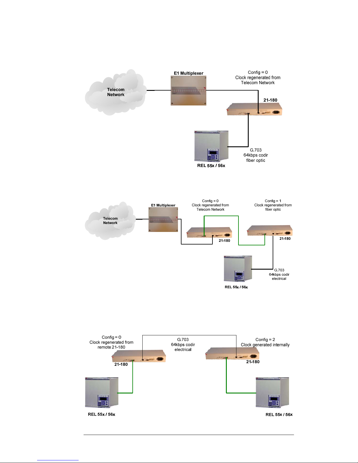
External clock
When HEX-switch is in position 0, the clock extracted from the signal received at the
G.703 64kbps Codir port is used. This is the normal configuration when connected to
a telecom network.
Fiber clock.
When HEX-switch is on position 1, the clock used is regenerated from fiber optic
interface. This can be used for example when G.703 Codir needs to be galvanic
isolated.
Internal clock – “Master mode”
When HEX-switch is on position 2, the clock used is generated by an internal clock.
This is for example used when two 21-180 are directly connected to each other with
galvanic cables. Only one 21-180 shall have this configuration.
15
Start and usage.
Power on.
Connect the power cord to the 21-180 and then connect to a power supply with PE,
(Protective Earth/ground connection).
The “LO”-LED shall be lit green. If not, try to cross-connect the fibers at one end of
the link.
LED-status.
There are 12 LED-indicators at the front panel.
Power
A green LED lit, within 5 seconds, when power is connected to the unit.
Link
A green LED lit when G.703 Codir interface receives correct coded G.703 Codir
signal.
16

1 , 2 , 4 , 8
Yellow LEDs. Marks the position of the Config switch. The four LEDs forms a
binary value, lit LEDs, corresponding to the 16 positions of the Config switch. Only
position 0, 1 and 2 of the configuration switch are used. LEDs 4 and 8 shall always be
“black”.
MLA
Memory Local Alarm. Normally off/dark. This indication has the same function as
“LA” with an additional memory function. Is lit red if the unit has detected an “LA”-
error, and stays lit until the “Reset”-button is pressed.
MRA
Memory Remote Alarm. Normally off/dark. Is red if when the remote unit of the
fiber optic link has detected an error. This indication has a memory function. Any
remote error will be indicated until “Reset”-button is pressed.
TXD
A yellow LED indicates data sent at selected electrical interface.
RXD
A yellow LED indicates data received at selected electrical interface.
LA
Local Alarm. Normally off. Is lit red if the fiber optic link monitoring has detected a
communication error on the incoming fiber.
LO
Link OK. Green when the fiber optic link is operating correctly.
17

18
Technical support
Before contacting technical support, we beg you to first read the manual once again..
If you still have problems or questions, don’t hesitate to contact help desk. Please
gather all relevant information, including serial number, about your installation before
contacting help desk.
Our technical support can be reached at:
Fibersystem AB
Gardsfogdevagen 18B
S-16866 Bromma
Sweden
Telephone: +46-8-564 828 80 • telefax: +46-8-28 33 50
Web: http://www.fibersystem.se/
E-mail addresses can be found on our web-site.
CE - mark
The product described in this manual, is designed to apply to the specifications of the
EMC directive 89/336/EEC and to low voltage directive 73/23/EEC
-:-
Table of contents
Other Fibersystem Media Converter manuals


