Fibersystem 21-216 User manual
FS18132-Technical-manual-21-216-Secure-Series-R1-v3
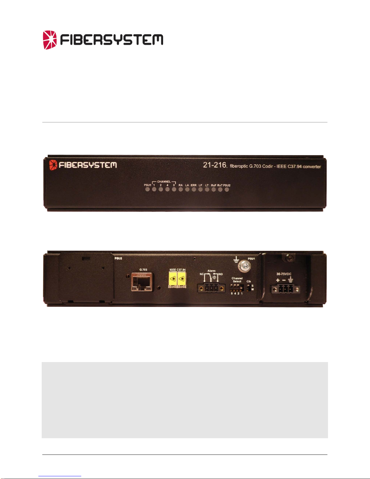
Fiber Optical Converter -21-216 Secure Series
G.703 Codir -IEEE C37.94
Technicalmanual

About this manual
About the contents of this manual
The information in this document may be changed at any time without notice.
Table of Contents
About the contents of this manual i
Table of Contents i
Version and revision history. 1
Revision history for product: 1
Revision history for this document. 1
Document properties. 1
Author. 1
Functional 2
IEEE C37.94 2
G.703 Codirectional interface - Codir 2
Features 3
Fiberoptic and data transfer protocol 3
Power Supply 3
Physical size 3
Environmental conditions 3
Unpacking. 4
Product 21-216 consists of: 4
Installation. 6
Serial number. 6
Connections on Rear side panel. 6
G.703 64kbit/s Codir Port. 7
Functional earth/ground. 7
Configuration 8
Start and usage. 8
Power on. 8
LED-status. 8
PSU1 8
CHANNEL 8
RA 9
LA 9
ERR 9
LF 9
LT 9
RxF 9
RxT 9
PSU2 (Optional second power supply) 9
Alarm 9
Technical support 10
CE - mark 10

1
Version and revision history.
Revision history for product:
Revision R1.
Product released for serial production. 2018-01-31.
Revision history for this document.
Revision AK0.
2018-01-30, LaJo, document created.
Revision R1.
2018-02-02, OsLi, Product released for serial production.
Document properties.
Last saved: 01/03/2018 13:58:00
Document name: 90-20-0125 Technical Manual 21-216 ½19" Secure Series Revision 1
Author.
Created by Lars Jonsson.
Last saved by Oscar Lindberg.

2
General description
Functional
The 21-216, Fiber Optical Converter G.703 Codir – IEEE C37.94 is intended to
extend distance and galvanic isolate the teleprotection equipment for substations
connection to multiplexers.
IEEE C37.94
The standard “IEEE C37.94-2002, IEEE Standard for N times 64 Kilobit per Second
Optical Fiber Interfaces between Teleprotection and Multiplexer Equipment”
describes a fiberoptic intra-substation communication links between
teleprotection equipment and multiplexers.
G.703 Codirectional interface - Codir
The standard “G.703 64kbit/s codirectional interface” describes a galvanic
interface commonly used by teleprotection equipment for connection to
multiplexers.

3
Features
Fiberoptic and data transfer protocol
Data speed 2048kbps
Optical data
Wavelength 850nm
Fiber optical connector LC
Optical System budget 13dB with multimode fiber,
(62.5/125 um)
9dB with multimode fiber,
(50/125 um)
Typical distance 2km (6dB system margin for 62.5/125
and 3dB margin for 50/125).
Power Supply
DC input: 36-75VDC
AC input: 85-264 VAC, 50-60 Hz, + 20%,
or 120-370 VDC.
AC-connector IEC 320, 3pin, locking.
Power consumption <5 W,
Optional second removable power supply available.
Dimensions and Weight
Height 44 mm
Width 222 mm (without rack mount brackets).
Depth 228 mm (from front to back, connectors excluded).
Weight 1,4 kg
The unit is intended to be mounted in a 19” rack. For a single unit mount in 19”
rack, a Single Mounting Bracket is available.
Two units can also be mounted side-by-side using a Double Mounting Bracket
Kit.
By adjusting, the rack mount brackets, the unit can also be mounted on a wall or
similar.
Environmental conditions
Operating temperature -25 to +55 oC
Storage temperature -40 to +85 oC
Relative humidity operating 5 to 95 %
Relative humidity storage 5 to 95 % non condensing.

4
Unpacking.
Check that all packing material has no damage. If damages are discovered on
packing material, contact your shipping company, before unpacking.
The delivered product consists of several parts. Check that all parts are present
according to list, and have no damage.
Product 21-216 consists of:
Quantity
Part number
Description
1
1
21-216
Fiberoptic G.703 Codir – IEEE C37.94 converter
(Part number includes all parts in this list).
60-00-7264
Fiberoptic G.703 Codir – IEEE C37.94 converter - DC
60-00-7265
Fiberoptic G.703 Codir – IEEE C37.94 converter - AC
2
1
60-00-7268
Single Mounting Bracket
3
2
60-00-7270
Angle Bracket Kit
Incl 8 screws (50-65-3118).
4
1
50-65-6585
Power cord, AC connector IEC320, 3 pin locking
5
4
50-65-5030
Rubber feet
6
1
90-20-0125
This manual - Technical Manual 21-216 ½19" Secure Series
Revision 1
Accessories
7
2
60-00-7269
Double Mounting Brackets
Incl 12 screws.
8
1
60-00-7389
AC/DC Slim Power Module
9
1
60-00-7363
DC/DC Slim Power Module 19"
10
1
60-00-7271
Din Rail mounting kit
21-216, (Part number 60-00-7264 DC, 60-00-7265 AC)
21-216, (Part number 60-00-7264 DC)
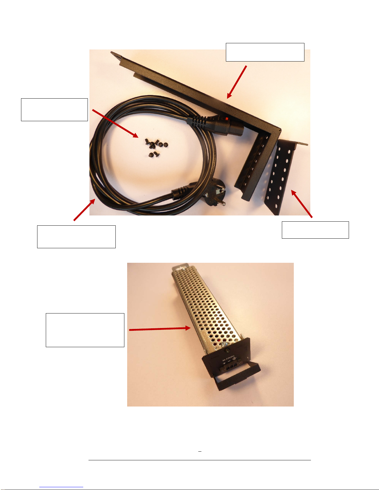
5
Power cord, AC connector
IEC320, 3 pin locking.
Single Mounting Bracket.
Screws for mounting
brackets.
Angle Bracket Kit.
Optional, extra removable
Slim Power Module. AC or
DC.
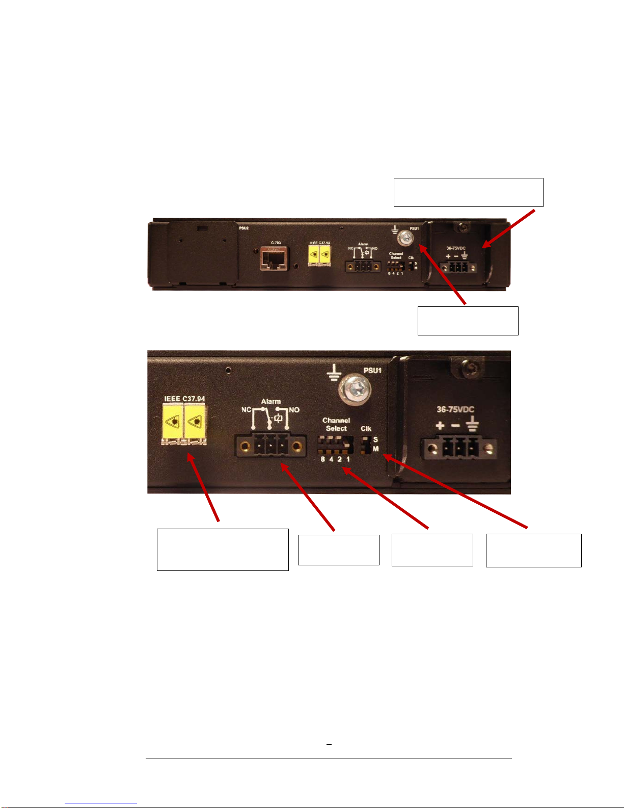
6
Power supply 1 (PSU1) - DC.
Functional ground
Fiber optic port – LC type,
with dust cover.
Alarm port.
DIP switch for
channel select.
Clock select,
Master or Slave.
Installation.
Serial number.
The products serial number is the best way for Fibersystem to identify the product.
If the serial number is not noted on your delivery notes, please add the serial
number to your own product documentation. This will be useful at future contact
with Fibersystem.
Connections on Rear side panel.
Confirm that the attenuation of the fiber optic cable, including splices and patch
cables, doesn’t exceed the system budget. Don’t forget to add a safety margin.
Minimum safety margin is 3dB.

7
Shielded (Metal house).
Pin 1
Pin 8
G.703 64kbit/s Codir Port.
Pinning of Codir port:
RJ45 pin
Name
Direction
1
Tx+ (TIP-out)
From 21-216 to multiplexer
2
Tx-(RING-out)
From 21-216 to multiplexer
4
Rx+ (TIP-in)
From multiplexer to 21-216
5
Rx-(RING-in)
From multiplexer to 21-216
Metalhouse
Shield
Cables shield must be connected
Use a cable with twisted pairs and a high quality shield. Only foil shielding is not
enough.
Rx+ and Rx- should form one twisted pair - Tx+ and Tx- another twisted pair.
A Cat5 S/FTP-cable, (Shielded/Foil Twisted Pair) used for example in Ethernet
communication is a good cable. The outer shield is a braided mesh around the
cable. In addition every twisted pair has a foil-shielding.
If a S/FTP patchcable for Ethernet is used, be aware that a cross-connected cable
has only the pairs on pin 1-2 and 3-6 cross-connected, the two remaining pairs are
not cross-connected.
Functional earth/ground.
To the left of the PSU1 power supply, a reference ground/earth screw is available.
Protective ground shall be connected to the IEC 320 power supply connector.

8
Configuration
Start and usage.
Power on.
Connect the power cord to the 21-216 and then connect to mains.
If the link doesn’t work, try to cross-connect the fibers at one end.
LED-status.
There are 13 LED-indicators at the front panel.
PSU1
A green LED lit when power is connected to the unit.
CHANNEL
Four yellow LED’s representing the channel chosen by DIP switch at rear panel.
The channel is “calculated” by adding the lit LED’s.
For example if LED 1and LED 2are lit 1+2=3 Channel 3 is chosen.
This means that data to/from G.703 codir-port is sent and received on the IEEE C37.94
protocol on the fiber.
The fiber protocols bits for N, named p,q,r,s in the IEEE 37.94 standard are always set to
N=1, (0,0,0,1). This means that 21-216 will send 1 channel and active data will be sent on
channel 3. The remaining 11 channels will have idle data - all ones. 21-216 will also accept
data on channel 3.
9
RA
Remote Alarm. A red LED indicating that the remote unit has encounter a fault condition
and has set the “Yellow Alarm bit” in the IEEE C37.94 protocol.
LA
Local Alarm. A red LED indicating that the 21-216 has encounter a fault in the received IEEE
C37.94 protocol – LOS Loss Of Signal. The “Yellow Alarm bit” is set in the outgoing IEEE
C37.94 protocol.
ERR
Error. A red LED indicating that the 21-216 has detected an internal error.
LF
Link Fiber. A green LED indicating that the 21-216 receives correct IEEE C37.94 frames, (no
LOS).
LT
Link Twisted pair/G.703 codir. A green LED indicating that 21-216 receives G.703 codir
64kbit/s protocol.
RxF
Receives data on fiber. A green LED indicating that 21-216 receives data in IEEE C37.94
format.
RxT
Receives data on Twisted pair/G.703 codir. A green LED indicating that 21-216 receives
data in G.703 codir protocol.
PSU2 (Optional second power supply)
A green LED lit when power is connected to the unit.
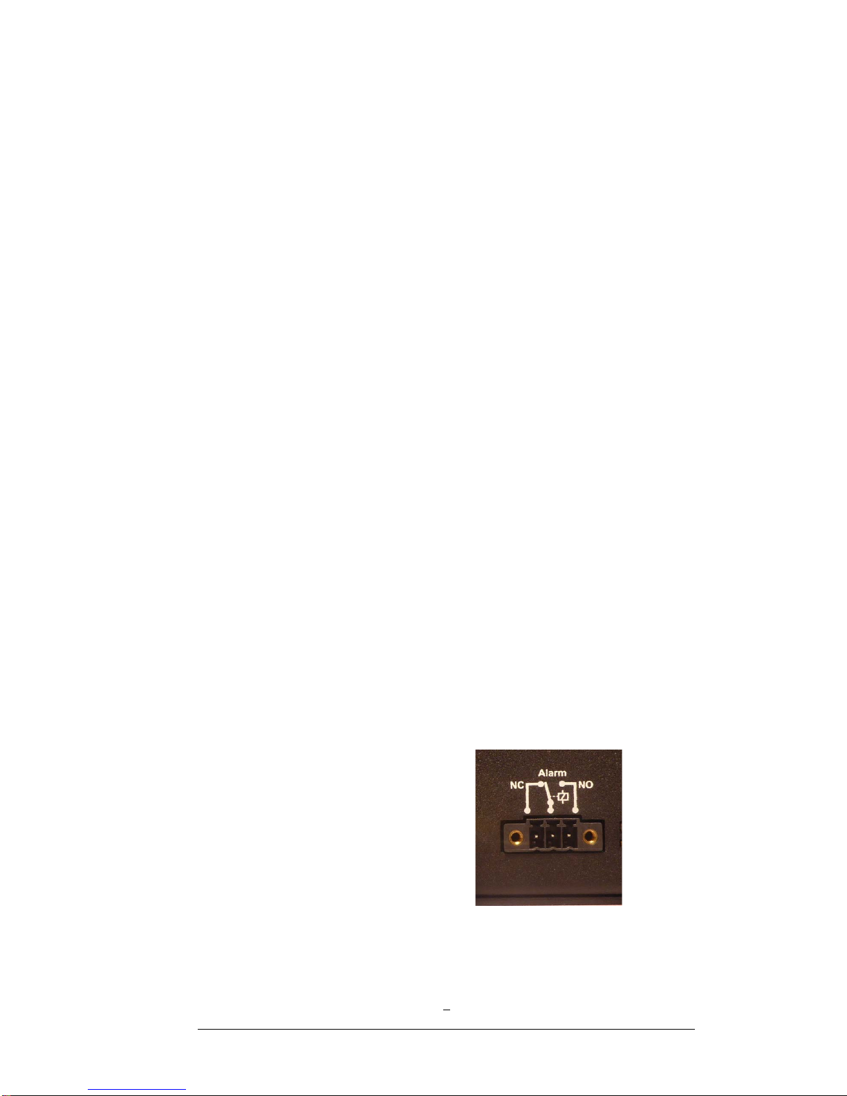
Alarm
Alarm out, is a 3-pin relay output. Normally when the G.703 link is up and the C37.04 link
is up and no errors, the NC pin and the common pin(in the middle) are closed, at the
same time the NO pin are open.
When G.703 link is down or C37.94 link is down or any other error is detected the relay
will switch to the opposite state.
Max switching voltage 440VAC, 300VDC.
Max switching current 8 A.

10
Technical support
Before contacting technical support, we ask you to first read the manual once again.
If you still have problems or questions, don’t hesitate to contact help desk. Please gather
all relevant information, including serial number, about your installation before contacting
help desk.
Our technical support can be reached at:
Fibersystem AB
Gårdsfogdevägen 18A
S-168 67, Bromma
Sweden
Telephone: +46-8-564 828 80
Web: http://www.fibersystem.com/
E-mail addresses can be found on our web-site.
CE -mark
The product described in this manual, is designed to apply to the specifications of the
EMC directive 89/336/EEC and to low voltage directive 73/23/EEC
-:-
This manual suits for next models
2
Table of contents
Other Fibersystem Media Converter manuals


