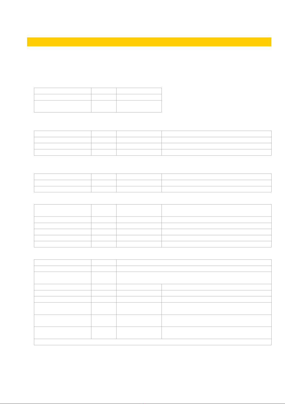
Jasper JasperMIDI User manual

JasperMIDI guide
Building and using JasperMIDI
Table of Contents
Introduction........................................................................................................................................... 1
Bill Of Materials..................................................................................................................................... 2
Building Choices................................................................................................................................... 3
Construction.......................................................................................................................................... 4
Installing in a Jasper enclosure.............................................................................................................5
Standalone use.....................................................................................................................................
Using JasperMIDI................................................................................................................................. 7
PCB Size and layout.............................................................................................................................8
Advanced – updating and hacking JasperMIDI.....................................................................................8
The Link Bus......................................................................................................................................... 9
Mapping Link to MIDI............................................................................................................................9
Introduction
JasperMIDI is a simple MIDI interface to allow you to
connect Jasper or other EDP link enabled equipment
like the vintage Wasp and Gnat Synths or Spider
sequencer to modern control equipment.
It can be used installed in an enclosure of a Jasper
synth, connected directly to the main PCB, or stand
alone in an external box. JasperMIDI has an optional
5V regulator allowing it to be powered with a V - 12V
supply, or this can be left out and it can be powered
using an existing regulated 5V. It can also take power
over the Jasper mini DIN connector.
JasperMIDI is based around an ATMega328P
processor programmed using the Arduino environment. The MIDI input is protected using a n137
opto-isolator. Spare analogue and digital ports are broken out, allowing for optional expansion or
additional features to be implemented.
The Link bus is quite a limited control method – Wasp type synthesisers only have 3 octaves of
control, purely monophonic. All devices on the same link bus will play or respond to the same note
at the same time.
v1 Page 1 of 9 November 2017

JasperMIDI guide
Bill Of Materials
There are no rare or expensive components in JasperMIDI. All the items can be obtained from the
usual electronics components suppliers. No special tools are required to build JasperMIDI – just
the usual soldering iron, solder and side cutters. If you wish to program the ATMega328 yourself,
then you will need an AVR compatible ISP programmer like the USBtinyISP.
Resistors
R11, R12, R13 3 220ohm
R2 1 1K
R1, R3, R4, R5, R ,
R7, R8, R9, R10
9 10K
Standard ¼W through hole resistors 1% or 5%
Capacitors
C8 1 15pF Small ceramic capacitor
C , C7 2 22pF Small ceramic capacitor for crystal
C1, C5, C9 3 0.1uF Small ceramic capacitor – decoupling
C3, C4 2 4.7uF Electrolytic capacitor
All capacitors 2.5mm lead spacing
Diodes
D1 1 1N4001
D3 1 1N4148
D2 1 LED 3mm standard LED (R2 sets brightness)
Integrated circuits etc
IC1 1 ATMEGA328P-P 28 pin DIP – programmed IC supplied with the
PCB
IC2 1 N137 Opto-isolator 8 Pin DIP
U1 1 MCP1702-5002 5V voltage regulator TO-92
Y1 1 1 Mhz Crystal HC49 type low
IC socket 1 8 pin For opto-isolator IC2
IC socket 1 28 pin For IC1
Misc
Pushbutton switch 1 Panel mounted push-button switch, push to close
Mini DIN socket 1 Shielded 8pin Mini DIN socket for Jasper Link connection
5 pin 180° DIN socket 2 Panel mounted socket for MIDI in & out – choose to suit your
enclosure.
JP1 1 2way pin header or use wire to jumper connection
P1, P2, P7 3 2way header MTA-100 or Molex-KK or wire to board
P8 1 3way header MTA-100 or Molex-KK or wire to board
P3
1 ICSP header 2x 3way pin header 2.54mm pitch. Needed if
you wish to update the firmware
P4 1 7way header MTA-100 or MolexKK 7way or 1x3way +
1x4way or wire to board
P5 1 8way header MTA-100 or MolexKK 7way or 2x4way or wire
to board
Hookup wire, mounting hardware, etc.
v1 Page 2 of 9 November 2017

JasperMIDI guide
Building Choices
There are options to consider before you start construction.
•If using JasperMIDI as an internal option
in a Jasper or Wasp synthesizer, then
you can omit the 5V regulator, D1 and
C3 and the 8pin mini-din socket. The
PCB can be wired directly to the 5V rail
in the synth.
•If using JasperMIDI as an external unit,
but connected to a Jasper synth using a
mini-din cable, it can be powered from
the host with the LINKPWR jumper on
the PCB is bridged, and enabled on the
Jasper synth.
•Alternatively you can power the JasperMIDI separately with a battery or DC jack. In which
case do not solder the LINKPWR jumper. The version illustrated above right uses a 9V battery
connected to a sliding switch.
•If you only want MIDI input, then you can omit one of the 5 pin DIN sockets.
•If you are happy with only having JasperMIDI operate on MIDI channel 1, you can omit the
pushbutton switch.
•MTA100 or Molex KK connectors can be omitted and the socket and Link cables can be wired
directly to the PCB. This is useful if your enclosure is quite small.
•A 78L05 5V regulator can be used in place of the low drop-out MCP1702 5V regulator – but
you will need to twist its legs to match the pinout.
•If you wish to interface with vintage Wasp or Gnat synths, you can wire a 7pin full size DIN
socket to the Link header on the PCB.
•If you are not likely to be reprogramming your JasperMIDI microcontroller, you can omit the
2x3 pin header.
v1 Page 3 of 9 November 2017

JasperMIDI guide
Construction
It is a fairly quick build. Solder the PCB as normal. Start with the smaller components – resistors
etc. and moving onto the taller items – IC sockets, voltage regulator, and the electrolytic capacitors.
Take care to get the polarity of the diodes, LED and electrolytic capacitors correct. For the LED and
electrolytic capacitors the longer (+ve) leg goes into the square shaped pad. Also the negative side
of the electrolytic capacitors are shaded on the PCB silk-screen. Before installing the ICs, connect
power to the PCB and check that you are getting 5V at the correct places.
Push button: Connect the push-button to the pads marked A0 and GND. This allows setting the
MIDI channel number. It is MIDI channel 1 by default, so leave the push-button out if you are happy
with this and don’t anticipate changing it.
MIDI DIN Soc et wiring: cut your wire long enough to reach from the JasperMIDI PCB headers to
where the sockets are located in your enclosure.
LED: The LED can be soldered directly to the PCB if you’re making an external box, or it can have
wires soldered to its pins so it can be positioned away from the PCB. A standard 2.54mm (0.1")
pitch MTA100/MolexKK or JST XH header can be soldered into the LED position on the PCB.
v1 Page 4 of 9 November 2017

JasperMIDI guide
Installing in a Jasper enclosure
If you built Jasper with a case including a speaker, then there will be enough room to install
JasperMIDI. You can omit soldering the mini-din socket, and the power regulator components. Use
hookup wire or ribbon cable to connect JasperMIDI to the Jasper main board. Use the 5V header
on the JasperMIDI PCB to the 5V pads (or connector) on the Link2 header. When connecting the
link port, make sure the wires are correctly connected. It’s a good idea to use coloured wire and
use a continuity tester so they don’t get mixed up.
The pin marked ‘G’ on the Link port header is a connection to GND, and can be omitted if you
connect 5V and GND to the 5V In header.
Remember to allow enough space in your enclosure for fitting the PCB and panel mounted
sockets, switch and LED.
The images below shows JasperMIDI installed behind the main Jasper PCB in an acrylic case. The
DIN sockets, LED, push button are connected using ribbon cable to JST crimp connectors on the
MIDI PCB. The Link port and 5V In connections are soldered on the PCB, but are terminated with
MTA100 plugs that connect to the Link2 header on the main PCB. Allow enough length on the
ribbon cable to reach the header.
v1 Page 5 of 9 November 2017

JasperMIDI guide
Standalone use
It is possible to put JasperMIDI in an external box – it can be powered by a Jasper using the mini-
DIN cable. If you wanted to make an external enclosure for use with the vintage Link equipment,
then it can be powered by battery, or external DC. It will work fine using a 9V battery connected to
the 12V header. A full-size 7-pin DIN socket to allow use with vintage EDP equipment could be
wired to the Link header on the PCB.
The image below show a simple 3D printed enclosure for JasperMIDI. It has two panel mounted
DIN sockets, and a push-button for programming the channel. It takes its power from the host
Jasper using the mini-din cable. The STL file for 3d printing can be downloaded from the
JasperSynth website.
v1 Page of 9 November 2017

JasperMIDI guide
Using JasperMIDI
Use standard 5pin DIN MIDI cables to connect JasperMIDI to your other equipment. When
connecting to a Jasper synth with an 8 way mini-DIN connector, make sure you use straight-
through connected shielded cable. The shield must be connected at both ends as this provides the
GND reference for the circuits.
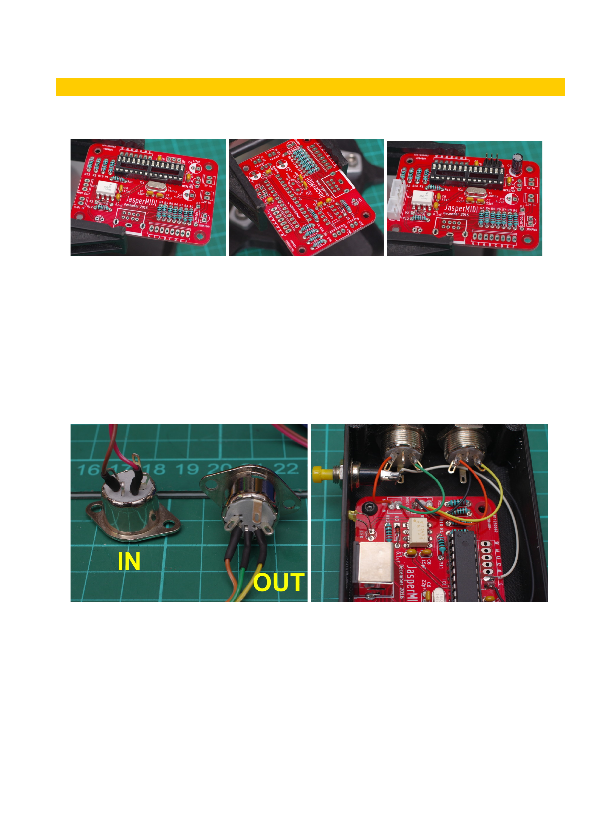
If you are using large 7pin DIN cables as used on original EDP equipment, do not get them mixed
up with the MIDI connectors – you may damage things.
JasperMIDI has a current draw of around 20mA to 23mA in use. If it is idle for a period of time, the
microcontroller goes to sleep drawing less than 8mA. Activity on the Link or MIDI input ports or a
press of the button will wake it up.
By default JasperMIDI will use MIDI channel 1. The only commands it responds to are NoteOn and
NoteOff (or NoteOn with velocity 0) commands for notes 3 -72 – 3 octaves from C0 to C3. The 2
octave Jasper/Wasp keyboard will produce notes in the top two of these octaves from C1 to C3.
Notes outside this range are ignored. Velocity or after-touch is ignored.
The Link port is purely monophonic – multiple synths connected together on a single Link bus will
simply play the same note at the same time. If you try to play two notes at the same time using a
Jasper keyboard and MIDI controller, glitchy results will occur as the different triggers try and
compete!
JasperMIDI keeps track of MIDI notes held down together, allowing for trilling and fast keyboard
playing. When playing a MIDI keyboard, the most recent key is played, even if other keys are held
down. When that key is released, the next most recent key still held down is played.
To change the MIDI channel, hold down the push-button for four seconds. This will put JasperMIDI
into a learning mode which lasts for 10 seconds. The LED will flash. The next MIDI command sent
from your controller will set the channel. This is saved in EEPROM, so will be persistent.
To reset it back to channel 1, hold down the button when the JasperMIDI is powered up.
MIDI output simply consists of NoteOn and NoteOff commands for the notes played over the Link
port. Jasper can be used as a very limited MIDI controller. JasperMIDI doesn’t pass through any
other MIDI data, but only outputs the notes played over the Link bus.
Due to limitations with the Wasp/Jasper envelope triggering circuitry you may find that fast
triggering of notes by MIDI won’t trigger the envelope. If using a keyboard (or Jasper’s touch
keyboard) you will find you have to lift your finger from the keyboard in order to retrigger envelope
on the next note. Likewise if using a sequencer, there should be a minimum of about 30mS
between notes sent over MIDI if you need the envelope to retrigger.
v1 Page 7 of 9 November 2017

JasperMIDI guide
PCB Size and layout
The PCB is 70mm x 50mm in size with rounded corners using a 5mm radius. 3mm diameter fixing
holes are inset 5mm from the edges.
5mm 15mm 30mm 65mm
5mm
45mm
Advanced – updating and hac ing JasperMIDI
JasperMIDI is implemented as a minimal
Arduino clone and can be programmed using
the Arduino environment. It has no USB
hardware on-board – so in order to program it
you must use an ISP programmer like the
USBtinyISP illustrated. This uses the pin
header above the ATMega chip.
This USBtinyISP was a kit from Adafruit and
works well. Other programmers are available
cheaply from Ebay and AliExpress.
Using the programmer it is possible to reflash
the firmware with an updated version, or even
your own code. If you are using an unused blank ATMega328, use the Arduino IDE to flash the
Arduino bootloader first. Select Arduino/Genuino Uno as the board type in the IDE.
The Arduino analogue pins A0 to A4 are broken out for further expansion. In the original firmware
written for JasperMIDI, A0 is used for a push-button that is used to set the MIDI channel. Also A4 is
used for a debug serial port, if a flag is set in the source.
These pins can be used for digital IO, or for analogue input. A5 is used for the LED. Digital pins D9
and D10 are also free, but not broken out on the PCB – however you can use these pins by
carefully soldering wires to the pads under the IC socket. Arduino digital pin D9 is pin 15 and D10
is pin 1 on the ATMega328P. Digital pins D11,D12 and D13 are used by the ICSP programmer –
so are broken out on the pin header.
v1 Page 8 of 9 November 2017

JasperMIDI guide
The Lin Bus
T A B C D E F
Trigger Note 1 lsb Note 2 Note 3 Note 4 msb Octave 1 lsb Octave 2 msb
The Link bus uses 5V TTL logic levels.
Notes are encoded as a number from 0-11 from top to bottom using bits A-D. The octave on bits E
and F from 0-2, 0=high, 1=mid, 2=low.
The trigger is a pulse approximately 50Hz when active, and the note data is decoded on its rising
edge.
When not actively playing a note, the lines on the Link bus should be put in a hi-Z state, in order
that other equipment can use the bus. On a microcontroller this usually means switching the pins
to Input mode with any internal pull-up resistors switched off.
C0 C0# D0 D0# E0 F0 F0# A1 A1# B1 C1G0 G0# C1#D1 D1# E1 F1 F1# A2 A2# B2 C2G1 G1# C2# D2 D2# E2 F2 F2# A3 A3# B3 C3G2 G2#
The Wasp/Jasper keyboard allows playing of the top two octaves, but by using the Link port
another octave is possible, shown in grey above. There is a hardware ‘bug’ in the Wasp/Jasper
decoding circuitry – the lowest C (C0 above) is not decoded, so it won’t play. The Gnat decoding
circuitry can play the lowest C.
The note codes are shown in decimal in the above graphic. Between the C#s and Cs there is a gap
of four – this is because the note numbers only count from 0-11 per octave. Numbers 12-15 are
skipped/ignored by the decoding logic in the synths.
Mapping Lin to MIDI
The following table shows the MIDI note numbers used by JasperMIDI, and the corresponding
number of each note on the Link bus:
Note Octave C0 C0# D0 D0# E0 F0 F0# G0 G0# A1 A1# B1
MI I Note 3 37 38 39 40 41 42 43 44 45 4 47
Link Note 48 43 42 41 40 39 38 37 3 35 34 33
Note Octave C1 C1# D1 D1# E1 F1 F1# G1 G1# A2 A2# B2
MI I Note 48 49 50 51 52 53 54 55 5 57 58 59
Link Note 32 27 2 25 24 23 22 21 20 19 18 17
Note Octave C2 C2# D2 D2# E2 F2 F2# G2 G2# A3 A3# B3 C3
MI I Note 0 1 2 3 4 5 7 8 9 70 71 72
Link Note 1 11 10 9 8 7 5 4 3 2 1 0
Note: C0 doesn’t play on Jasper/Wasp – but is OK on the Gnat.
v1 Page 9 of 9 November 2017
Table of contents
Popular Media Converter manuals by other brands

Pilz
Pilz PSEN enc m2 eCAM operating manual

MuxLab
MuxLab UHD-4K Quick installation guide

HEIDENHAIN
HEIDENHAIN AK ERM 2420 Mounting instructions

CHD Elektroservis
CHD Elektroservis P61-KBD user guide

TR-Electronic
TR-Electronic PROFI BUS QDH Series user manual

SamplexPower
SamplexPower VTC305-12-12 owner's manual

Lika
Lika SMAX-MB Series user guide

Checkpoint LAB
Checkpoint LAB Microcontroller-cafe USB-RS232 user guide

MyTek
MyTek Stereo96 DAC user manual

SYP
SYP SY-4KS Operation manual

Cambridge Audio
Cambridge Audio AZUR DacMagic 100 Technical specifications

Lika
Lika Posicontrol IF55 LIN CB Series Mounting instructions