Elgo LIMAX2M Series User manual

Operating Manual
SERIES LIMAX2M
Magnetic Absolute Shaft Information System
(Translation of the original operating manual)
Position measuring for lifting heights up to 130 meters
Travel speed up to 4 m/s
Insensitive to dirt, smoke and humidity
Resolution up to 0.0625 mm
Easy and flexible mounting
No referencing necessary
Magnetic tape may be installed vertically freely suspended or horizontally
Wear-free, contactless and noiseless measuring principle
D-103918 / Rev. 2 / 2020-02-07


Contents
- 3 -
1Contents
1Contents ............................................................................................. 3
2General.............................................................................................. 4
2.1 Information Operating Manual .............................................................................5
2.2 Explanation of Symbols ........................................................................................5
2.3 Statement of Warranties.......................................................................................6
2.4 Demounting and Disposal....................................................................................6
3Safety ................................................................................................. 7
3.1 General Causes of Risk........................................................................................7
3.2 Personal Protective Equipment...............................................................................7
3.3 Conventional Use ...............................................................................................8
4Transport and Storage ...................................................................... 9
4.1 Safety Instructions for Transport, Unpacking and Loading ..........................................9
4.2 Handling of Packaging Material ............................................................................9
4.3 Inspection of Transport ........................................................................................9
4.4 Storage .............................................................................................................9
5Product Features .............................................................................. 10
5.1 Functional principle...........................................................................................10
6Technical Data ................................................................................. 11
6.1 Identification ....................................................................................................11
6.2 Dimensions Sensor............................................................................................11
6.3 Dimensions Magnetic Tape ................................................................................12
6.4 Technical Data Sensor ....................................................................................... 12
6.5 Technical Data Magnetic Tape............................................................................13
7Installation and First Start-Up......................................................... 14
7.1 Operating Area ................................................................................................14
7.2 Description Mounting / Installation of the Sensor....................................................15
7.3 Description installation / Mounting of the Magnetic Tape ........................................16
8Connections and Interfaces ............................................................. 22
8.1 LEDs (Operating Status and Notices)....................................................................22
8.2 CAN Interface ..................................................................................................23
8.3 SSI Interface..................................................................................................... 29
8.4 RS422 and RS485* Interface ..............................................................................30
9Disturbances, Maintenance, Cleaning............................................. 34
9.1 Fault Clearance................................................................................................ 34
9.2 Re-start after Fault Clearance..............................................................................34
9.3 Maintenance.................................................................................................... 35
9.4 Cleaning .........................................................................................................35

Contents
- 4 -
10 Type Designation ............................................................................. 36
10.1 Accessories ......................................................................................................37
11 Index ................................................................................................ 43
2List of Figures
Figure 1: Sensor Construction.................................................................................................................. 10
Figure 2: Dimensions LIMAX2M ............................................................................................................... 11
Figure 3: Dimensions Magnetic Tape ....................................................................................................... 12
Figure 4: Installation with tension weight ................................................................................................... 15
Figure 5: Installation with spring............................................................................................................... 15
Figure 6: Mounting groove on the sensor.................................................................................................. 16
Figure 7: Assessment of the pretention of the magnetic tape ....................................................................... 17
Figure 8: Correct orientation of the magnetic tape..................................................................................... 18
Figure 9: Distance and orientation of the magnetic tape in relation to the sensor ......................................... 18
Figure 10: Assessment of the guiding rail of the tape in the sensor - twisted magnetic tape ........................... 19
Figure 11: Assessment of the guiding rail of the tape in the sensor - skewed mounting of the magnetic tape... 19
Figure 12: Assessment of the vertical alignment of the sensor ..................................................................... 20
Figure 13: LED signals on the upper side of the sensor............................................................................... 22
Figure 14: Protocol DS406...................................................................................................................... 23
Figure 15: Protocol DS417...................................................................................................................... 23
Figure 16: Setting the Heartbeat Cycle Duration........................................................................................ 24
Figure 17: Setting the Sending Cycle for the position data .......................................................................... 25
Figure 18: Saving the parameters............................................................................................................. 25
Figure 19: Changing the device into the Operational Mode....................................................................... 26
Figure 20: Changing the device into the Pre-operational Mode .................................................................. 26
Figure 21: Changing the device into the Stopped Mode............................................................................. 26
Figure 22: Changing into the LSS Configuration Mode .............................................................................. 27
Figure 23: Saving the parameters in the LSS Mode .................................................................................... 27
Figure 24: Setting the Baud rate............................................................................................................... 28
Figure 25: Setting the node-ID................................................................................................................. 28
Figure 26: Data Protocol SSI.................................................................................................................... 29
Figure 27: Data Protocol Version 4221 .................................................................................................... 30
Figure 28: Data Protocol Versions 4220 / 4850........................................................................................ 30
Figure 29: Connection to a RS422 Master ................................................................................................ 32
Figure 30: Cable M12F5 - open cable ends ............................................................................................. 37
Figure 31: Cable M12F5 - D9M.............................................................................................................. 38
Figure 32: Cable M12F - open cable ends ............................................................................................... 38
Figure 33: Cable M12F - D9M1.............................................................................................................. 39
Figure 34: Mounting angle...................................................................................................................... 40
3List of Tables
Table 1: Configuration of CANopen DS406 ............................................................................................. 23
Table 2: Configuration of CANopen DS417 ............................................................................................. 23
Table 3: Pin Assignment CAN .................................................................................................................. 23
Table 4: Pin Assignment SSI..................................................................................................................... 29
Table 5: Error-codes of an addressable LIMAX2M ..................................................................................... 32
Table 6: Pin Assignment RS422................................................................................................................ 33
Table 7: Pin Assignment RS485................................................................................................................ 33
Table 8: Connections Cable M12F5 - open cable ends ............................................................................. 37
Table 9: Connections Cable M12F5 - open cable ends ............................................................................. 38
Table 10: Connections Cable M12F - open cable ends ............................................................................. 39
Table 11: Connections M12F - D9M1...................................................................................................... 39

General
- 5 -
4General
4.1 Information Operating Manual
This manual contains important information regarding the handling of the device. For your own safety and op-
erational safety, please observe all safety warnings and instructions.
Precondition for safe operation is the compliance with the specified safety and handling instructions. Moreover,
the existing local accident prevention regulations and the general safety rules at the site of operation have to be
observed.
Please read the operating manual carefully before starting to work with the device! It is part of the product and
should be kept close to the device and accessible for the staff at any time. The illustrations in the manual are for
better demonstration of the facts. They are not necessarily to scale and can slightly differ from the actual design.
4.2 Explanation of Symbols
Special notes in this manual are characterized by symbols.
The notes are introduced by signal words which express the magnitude of danger.
Please follow this advice and act carefully in order to avoid accidents and damage and injuries.
Warning notes:
DANGER!
This symbol in connection with the signal word “Danger” indicates an immediate danger for
the life and health of persons.
Failure to heed these instructions can result in serious damage to health and even fatal injury.
WARNING!
This symbol in connection with the word „Warning” means a possibly impending danger for
the life and health of persons.
Failure to heed these instructions can result in serious damage to health and even fatal injury.
CAUTION!
This symbol in connection with the signal word “Caution” indicates a possibly dangerous
situation. Failure to heed these instructions can lead to injuries or damage of property.
Special safety instructions:
DANGER!
This symbol in connection with the signal word “Danger” indicates an immediate danger for
the life and health of persons due to voltage. Failure to heed these instructions can result in
serious damage to health and even fatal injury. The operations may only be carried out by a
professional electrician.
Tips and recommendations:
NOTE!
…points out useful tips and recommendations as well as information
for an efficient and trouble-free operation.
References:
(1.2) Marks a reference to chapter 1.2 of this manual.
(DOC 3.4) Marks a reference to chapter 3.4 of the document DOC.
General
- 6 -
4.3 Statement of Warranties
The statement of warranties is enclosed separately in the sales documents.
Guarantee
The producer guarantees the functional capability of the process engineering and the selected parameters. The
period of warranty is one year and begins with the date of delivery.
4.4 Demounting and Disposal
Unless acceptance and disposal of returned goods are agreed upon, demount the device considering the safety
instructions of this manual and dispose it with respect to the environment.
Before demounting:
Disconnect the power supply and secure against re-start. Then disconnect the supply lines physically and dis-
charge remaining energy. Remove operational supplies and other material.
Disposal:
Recycle the decomposed elements:
Metal components in scrap metal
Electronic components in electronic scrap
Recycle plastic components
Dispose the remaining components according to their material consistence
CAUTION!
Wrong disposal causes environmental damages! Electronic scrap, electronic components,
lubricants and other auxiliary materials are subject to special refuse and can only be disposed
by authorized specialists!
Local authorities and waste management facilities provide information about environmentally sound disposal.
Safety
- 7 -
5Safety
CAUTION!
Please read the operating manual carefully, before using the device! Observe the installation
instructions! Only start up the device if you have understood the operating manual.
The operating company is obliged to take appropriate safety measure.
The initial operation may only be performed by qualified and trained staff.
Selection and installation of the devices as well as their embedding into the controlling system
require qualified knowledge of the applicable laws and normative requirements on the part of
the machine manufacturer.
5.1 General Causes of Risk
This chapter gives an overview of all important safety aspects to guarantee an optimal protection of employees
and a safe and trouble-free operation. Non-observance of the instructions mentioned in this operating manual
can result in hazardous situations.
5.2 Personal Protective Equipment
Employees have to wear protective clothing during the installation of the device to minimize danger of health.
Therefore:
Change into protective clothing before performing the works and wear them throughout the process.
Additionally observe the labels regarding protective clothing in the operating area.
Protective clothing:
PROTECTIVE CLOTHING
… is close-fitting working clothing with light tear strength, tight sleeves and without distant
parts. It serves preliminarily for protection against being gripped by flexible machine parts.
Do not wear rings, necklaces or other jewelry.
PROTECTIVE GLOVES
…for protecting the hands against abrasion, wear and other injury of the skin.
PROTECTIVE HELMET
…for protection against injuries of the head.

Safety
- 8 -
5.3 Conventional Use
The product described in this manual was developed to execute safety-related functions as a part of an entire
assembly or machine. It is the responsibility of the manufacturer of a machine or installation to ensure the prop-
er operation of the system. The ELGO-device is conceived only for the intended use described in this manual.
The LIMAX2M - ELGO- length measuring system serves only to measure lengths.
CAUTION!
Danger through non-conventional use! Non-intended use and non-observance of this operat-
ing manual can lead to dangerous situations.
Therefore:
Only use the device as described
Strictly follow the instructions of this manual
Avoid in particular:
Remodeling, refitting or changing of the construction or single components with the in-
tention to alter the functionality or scope of the device.
Claims resulting from damages due to non-conventional use are not possible.
Only the operator is liable for damages caused by non-conventional use.

Transport and Storage
- 9 -
6Transport and Storage
6.1 Safety Instructions for Transport, Unpacking and Loading
CAUTION!
Transport the package (box, palette etc.) professionally. Do not throw, hit or fold it.
6.2 Handling of Packaging Material
Notes for proper disposal: 2.5
6.3 Inspection of Transport
Check the delivery immediately after the receipt for completeness and transport damage.
In case of externally recognizable transport damages:
Do not accept the delivery or only accept under reserve.
Note the extent of damages on the transportation documents or delivery note.
File complaint immediately.
NOTE!
Claim any damage immediately after recognizing it. The claims for damage must be filed in
the lawful reclaim periods.
6.4 Storage
Store the device only under the following conditions:
Do not store outside
Keep dry and dust-free
Do not expose to aggressive media
Protect from direct sun light
Avoid mechanical shocks
Storage temperature (6 Technical Data) needs to be observed
Relative humidity (6 Technical Data) must not be exceeded
Inspect packages regularly if stored for an extensive period of time (>3 months)

Product Features
- 10 -
7Product Features
The absolute shaft information system LIMAX2M with its significant advantages is a particularly affordable, non-
sensitive and easy-to-install alternative to conventional shaft information systems. Due to the absolute measure-
ment principle, referencing is not required after commissioning.
Compared to other shaft information systems, LIMAX2M is characterized by an extraordinarily low price. LI-
MAX2M is able to cover lifting heights up to 130 meters and speeds up to 4 m/s. The standard interfaces are
CAN, RS422 or SSI. We also provide customized solutions on request.
This measuring system provides smallest sensor of the entire LIMAX series. With these small space requirements,
LIMAX2M is ideal for remodelling and modernization.
A simple and flexible mounting ensures quick installation or replacement of the measuring system.
Features:
Robust measuring principle to dirt, smoke and humidity
Easy and flexible mounting
No reference necessary
Wear-free, contactless and noiseless measuring principle
7.1 Functional principle
The tape carries the unique positioning information as a magnetic code. It is installed free hanging in the eleva-
tor shaft by use of a mounting kit. The sensor head is mounted to the elevator car. While the actual measure-
ment is contactless the tape must be kept within a maximum distance to the sensor head. Therefore, the tape is
guided along the sensor by use of the polymer tape guide which is an integral component of the sensor head.
The magnetic measurement principle is extremely robust. Dust, dirt and humidity do not affect the measurement
in any way. Also, smoke and even higher temperatures have no influence on the measuring quality. Therefore,
LIMAX2M is particularly suited for application in fire fighter elevators. Also is the tape robust enough to with-
stand the sometimes-harsh conditions in elevator shafts.
7.2 Sensor Construction
The LIMAX2M sensor consists of the following components:
Sensor housing with integrated signal LEDs for signaling various states.
M12 round connector (5-pin) for power supply and communication with the lift control.
Guide rail with plastic underlay (keeps the magnetic tape at a defined distance from the sensor).
Holding plate for mechanical fixation of the polymer guide rail.
Figure 1: Sensor Construction
M12 Connector Signal LEDs
Guide unit:
Holding plate
for guide rail
Guide rail
Underlay
Sensor housing

Technical Data
- 11 -
8Technical Data
8.1 Identification
The type label serves for the identification of the unit. It is located on the housing of the sensor and gives the
exact type designation (=order reference, see type designation) with the corresponding part number. Further-
more, the type label contains a unique, traceable device number.
When corresponding with ELGO always indicate this data.
8.2 Dimensions Sensor
Figure 2: Dimensions LIMAX2M

Technical Data
- 12 -
8.3 Dimensions Magnetic Tape
Figure 3: Dimensions Magnetic Tape
8.4 Technical Data Sensor
LIMAX2M (Standard version)
Mechanical Data
Measuring principle
absolute
Repeat accuracy
±1 mm
System accuracy in µm at 20°C
±(1000 + 50 x L) L = measuring length in meter
Basic pole pitch
8 mm
Sensor housing material
aluminium
Sensor housing dimensions
L x W x H = 247 x 54 x 27 mm
Necessary type
AB20-80-10-1-R-D-15-BK80
Maximum measuring length
130 m
Connection
M12 round connector
RJ45 plug with fixed cable outlet on request
Weight
approx. 320 g
Sensor cable
3 m standard cable length (other on request)
Electrical Data
Supply voltage
10 … 30 VDC
Residual ripple
< 200 mVpp
Power input
max. 0.2 A
Interfaces
12
Resolution
12
Speed
max. 4 m/s
Conditions
Storage temperature
−20 … +85 °C
Operation temperature
−10 … +70 °C
(−25 … +85 °C on request)
Humidity
max. 95 %, not condensing
Protection class
IP54 (IP67 on request)
Scale 5:1

Technical Data
- 13 -
8.5 Technical Data Magnetic Tape
The magnetic tape consists of two components:
The actual magnetic tape which carries the position information
A mechanical stainless steel back iron
TEMPLATE Magnetic Tape AB20-80-10-1-R-D-15-BK80
Coding
absolute, one track system
Pole pitch
8 mm
Operation temperature installed
−20 … +65 °C
(−20 … +80 °C when using without adhesive tape, options „B“ or „D“)
Storage temperature uninstalled
Short-term: −10 … +60 °C
Medium-term: 0 …+40 °C
Long-term: +18 °C
(−20 … +80 °C when using without adhesive tape, options „B“ or „D“)
Gluing temperature
+18 °C … +30 °C
Relative humidity
max. 95 %, non-condensing
Accurateness 20°C in µm
± (1000 + 50 x L) L = measuring length in meters
Material carrier tape
Precision strip 1.4310 / X10CrNi 18-8 (EN 10088-3)
Double-faced adhesive tape
3M-9088 (observe instructions), others on request
Dimensions
without adhesive tape:
10 mm (±0.1) x 1,35 mm (±0.11)
with adhesive tape (excl. carrier):
10 mm (±0.1) x 1,56 mm (±0.13)
with adhesive tape (incl. carrier):
10 mm (±0.1) x 1.63 mm (±0.14)
Length expansion coefficient
16 x 10-6 1/K
Thermal length expansion
∆L[m] = L[m] x [1/K] x ∆[K]
(L = tape length in meters, ∆= relative temperature change)
Bending radius
min. 150 mm
Available lengths
max. 260 m
Weight magnetic tape
ca. 62 g/m (incl. magnetic tape and cover tape)
Tape imprint
ELGO standard, printing color black, digit height >= 5 mm
Influence of external magnets
External magnetic fields must not exceed 64 mT (640 Oe; 52 kA/m on
the surface of the magnetic tape as this could damage or destroy the
code on the tape.
Protection class
IP65
Installation and First Start-Up
- 14 -
9Installation and First Start-Up
CAUTION
Please read the operating manual carefully before using the device! Strictly observe the Instal-
lation instructions!
In case of damage caused by failure to observe this operating manual, the warranty expires.
ELGO is not liable for any secondary damage and for damage to persons, property or assets.
The operator is obliged to take and to realize appropriate safety measures.
The operator is obliged to take appropriate safety measures. The first start-up may only be
performed by staff that has been trained and authorized by the operator.
9.1 Operating Area
WARNING!
Do not use the device in explosive or corrosive environments!
The device must not be installed close to sources of strong inductive or capacitive interference
or strong electrostatic fields!
CAUTION!
The electrical connections must be made by suitably qualified personnel in accordance with
local regulations.
The device may be designed for switchboard mounting. During work on the switchboard, all
components must be de-energized if there is a danger of touching the energized parts!
(protection against contacts)
Wiring works may only be performed in the de-energized state!
Thin cable strands have to be equipped with end sleeves!
Before switching on the device, connections and plug connectors have to be checked!
The device must be mounted in a way that it is protected against harmful environmental influ-
ences such as splashing water, solvents, vibration, shock and severe pollution and the operat-
ing temperature must not be exceeded.

Installation and First Start-Up
- 15 -
Sensor
Magnetic tape
Guide rail
Upper tape fixation
Tension weight
Sway guard
Upper tape fixation
Sensor
Magnetic tape
Spring
Guide rail
9.2 Description Mounting / Installation of the Sensor
9.2.1 Installation Principle
Figure 4: Installation with tension weight
Figure 5: Installation with spring
LIMAX2M can be installed at any position in the shaft, depending on space situation and layout of the particular
elevator installation.
The magnetic tape is installed freely suspended in the shaft. It can be fixed with the RMS mounting kit (available
as option) on the guide rail. Alternatively fixation in the shaft head is either on beams or directly bolted into the
ceiling. The necessary tension in the tape is provided by a tension weight of about 5kg. A sway guard at the
bottom is recommended. This will keep the tape from swaying in an uncontrolled manner which may cause
damage to the tape or other components in the shaft. Alternatively the magnetic tape can be tensioned by a
spring.
The sensor head can be mounted onto the car body or car frame –again depending on the specific conditions
of the elevator.
Installation and First Start-Up
- 16 -
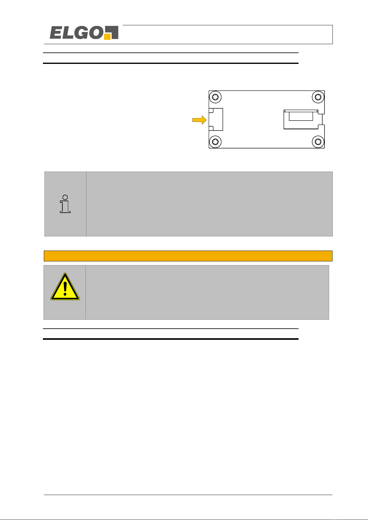
9.2.1 Installation of the Sensor
The sensor is fixated on the cabin or on the car frame. The mounting position is basically determined by the
condition.
The integrated mounting notch on the housing of the
sensor head allow for a very simple and self-
explanatory installation from one side. You can either
use M6 hexagon head screws (DIN 933) or M6
square nuts (DIN 562), to mount the system at the
desired position.
Figure 6: Mounting groove on the sensor
NOTE
During installation of the magnetic tape in the sensor, pay attention to the marks on the mag-
netic tape and on the sensor head.
Wrong orientation of tape vs. Sensor head will yield incorrect position readings!
The arrows printed on the magnetic tape and sensor head point in positive counting direction
(in the direction of the shaft head)!
9.3 Description installation / Mounting of the Magnetic Tape
NOTE External Magnetic Fields
The influence of the magnetic tape by magnetic fields must be avoided!
The magnetic tape must not come into direct contact with other magnetic fields (e.g. per-
manent magnets, magnetic clamps, electromagnets, magnetic stands)! This may cause
irreparable damage, which will compromise the measuring accuracy or even the function-
ing.
9.3.1 General Information
The technology has proven to be highly robust.LIMAX2M will work under the most adverse environmental condi-
tions. Extreme temperatures, high moisture and excessive soiling will not alter the information coded onto the
tape nor will these conditions affect reading precision of the sensor. Even weak magnetic fields such as they are
generated by door magnets can be tolerated.
If some basic rules and guidelines are followed LIMAX2M systems require a minimum amount of installation and
maintenance effort while offering maximum lifetime.
One important issue to consider is the protection of the magnet tape against mechanical wear. The LIMAX2M
tape consists of two components:
The magnetic tape which actually carries the position information
A protective steel tape which gives the mechanical properties
Installation and First Start-Up
- 17 -
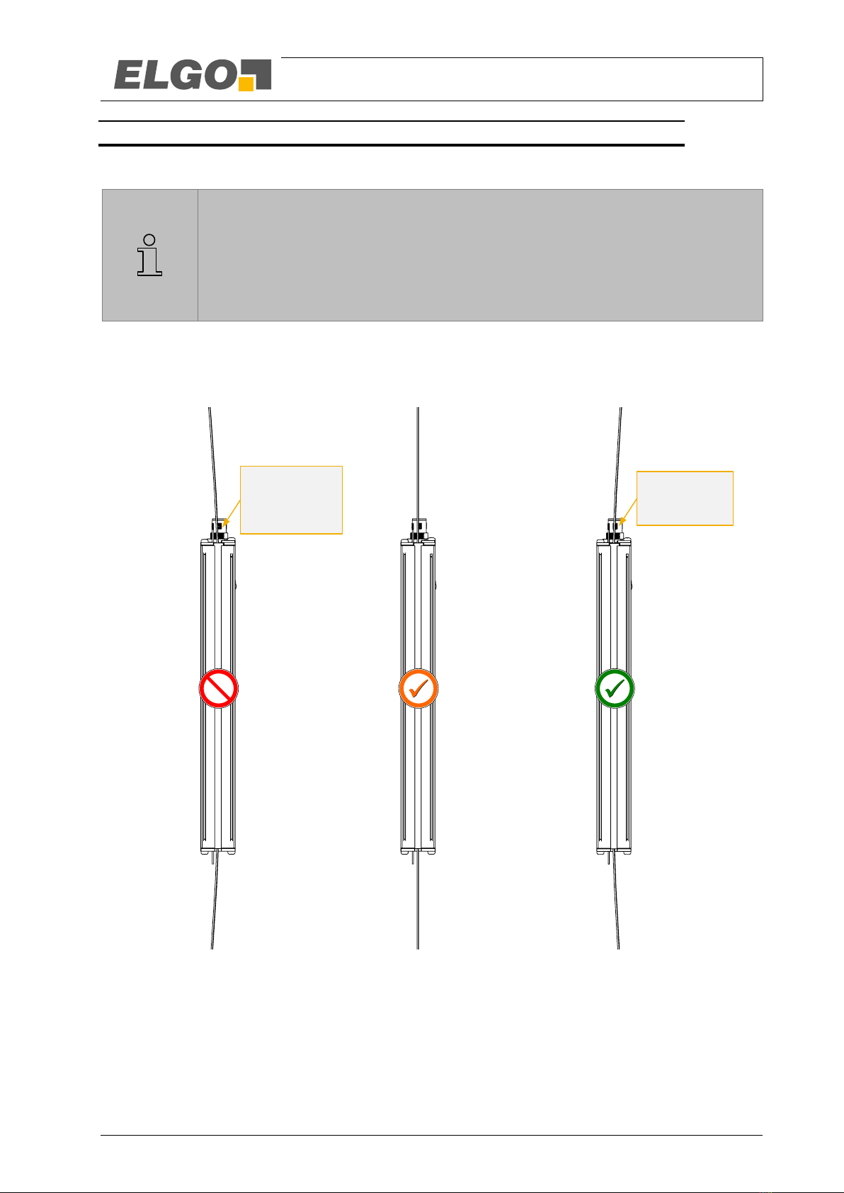
9.3.2 Installation Concept
9.3.2.1 Basic principle for the mounting
NOTE!
The magnetic tape itself is not designed to withstand excessive mechanical wear. It is there-
fore important to ensure that the system is installed such that the mechanical contact between
tape and sensor head is mainly between the steel tape and the polymer sensor guide. These
two materials have been specifically paired for this application.
Avoiding contact between the magnetic side and the sensor could be achieved with a perfectly perpendicular
installation of the band. Yet, in reality this is not practicable. It is therefore preferable to install the tape with a
horizontal offset from the sensor. During operation this method will result in a forced contact between the steel
side of the band and the polymer guide of the sensor which guarantees an optimal operation of the system.
Figure 7: Assessment of the pretention of the magnetic tape
Tape touches
the guide with
the magnetized
side
Wrong
Constanc contact
between magnetized side
and sensor housing lead
to abrasion
Tolerable Recomended
Vertical alignment
minimal contact between
tape and sensor
Enforced conact between
steel tape and polymer
housing
Tape touches
the guide with
the steel side
Installation and First Start-Up
- 18 -
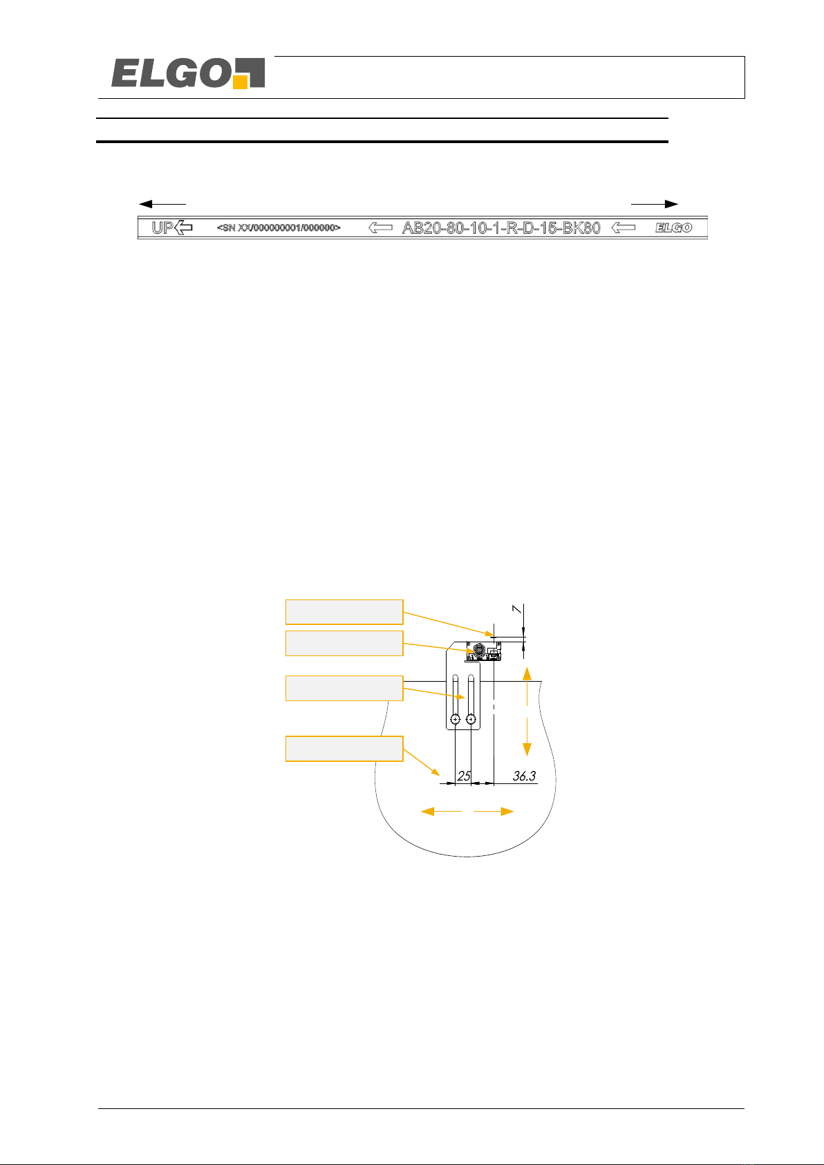
9.3.3 Installation Procedure
1. Attach the top end of the tape in the shaft head. Ideally use an ELGO Mounting Kit. Check for correct
orientation of the tape. The arrows on the magnetic side must point in upward direction.
Figure 8: Correct orientation of the magnetic tape
2. The magnetic side of the tape must face the sensor body. In most situations this means that the steel side
points to the shaft wall.
3. Drive down the shaft with inspection speed and unroll the tape. The ELGO tape packaging system has
been specifically designed for this purpose. The tape can be unwound directly from the box without open-
ing.
4. Attach the tension weight (about 7.5 kg) at the bottom end of the tape in the shaft. Secure the tape with a
sway guard. Pay attention to a proper vertical mounting of the tape.
If you use dowels to fix the tape in the shaft, tighten the spring such, that the according tractions results to
minimum 7.5 kg. When using the ELGO Mounting Kit RMS/RMS90 this is equivalent to a spring elonga-
tion of about 90mm.
Note that slightly higher tensile forces are never a problem, but avoid under-tensioning. In higher build-
ings it may even be preferable to slightly increase the tension in order to prevent flapping of the tape dur-
ing operation. However, if correctly installed tensile forces of more than 10 kg should never be necessary.
5. Drive the car to the middle of the shaft.
6. Attach the sensor to the car. The side with the cable outlet and the LED’s must face upward.
7. Adjust the sensor using the tape as a reference. First, align sensor and magnet band on their centerline.
Figure 9: Distance and orientation of the magnetic tape in relation to the sensor
8. Adjust now the distance between sensor and tape. Up to a travel height of 50m we recommend an offset
of at least 7 mm. This will ensure steady contact between steel side of the band and the polymer guide of
the sensor. This level can be increased later, if it turns out that the band still rubbing with the magnetic
side on the sensor.
In higher installations this distance may be increased by the initial assembly up to 5 cm.
Pay attention to a perpendicular alignment of the sensor. Misalignment will lead to increased wear.
9. Pass the tape through the sensor. Loosen the splint-pin and release the polymer guide. Insert the tape and
re-attach the guide with the tape in its position.
10. Pay attention that the pad does not slip after removal of the polymer guide from the aluminium guide out
and drops down in the shaft.
11. Check for proper alignment of band vs. sensor. Any angular offset should be corrected.
Shaft head Shaft pit
7.
8.
Mounting Angle
Magnetic Tape
Car
Sensor
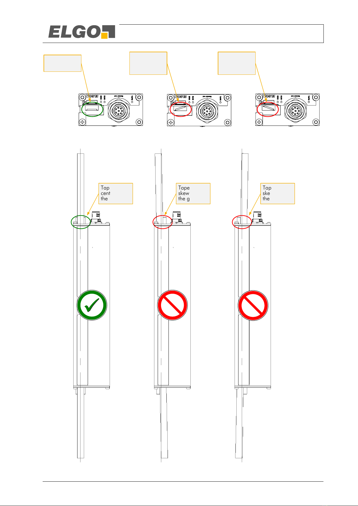
Installation and First Start-Up
- 19 -
Figure 10: Assessment of the guiding rail of the tape in the sensor - twisted magnetic tape
Figure 11: Assessment of the guiding rail of the tape in the sensor - skewed mounting of the magnetic tape
Tape is flat
in the guide
Tape is
skewed in
the guide
Tape is
skewed in
the guide
Tape is
centered in
the guide
Tape is
skewed in
the guide
Tape is
skewed in
the guide

Installation and First Start-Up
- 20 -
12. IMPORTANT: Installation Check!
Values for tape tension and offset between tape and sensor are guidelines based on experience. But in
any case, a proper check after installation is mandatory. It must absolutely be avoided that the magnetic
side constantly grinds on the sensor body during operation.
Run an inspection trip along the complete shaft. Observe the system and pay attention to the respective
positions of band and sensor. You have achieved an optimal installation if the steel side of the tape is
constantly pressed slightly against the polymer guide of the sensor. At some points in the shaft also dou-
ble-check on the bottom side of the sensor. If the sensor is tilted it may look good on top but the tape can
still grind along the bottom edge of the sensor.
Figure 12: Assessment of the vertical alignment of the sensor
Recomended Wrong vertical
alignment
Table of contents
Other Elgo Industrial Equipment manuals


