Fichtelbahn ReadyServoTurn User manual
FichtelBahn
WEEE-Reg.-Nr.DE52732575
FichtelBahn
ReadyServoTurn
4-fach BiDiB-Servodecoder
with 4x Relais and 4x Input
Line
Ready
Made in Germany
Power
12V - 18V
DC
ŝŝͲ/ĚĞŶƟĨLJ
TERM
DCC BiDiB
ĐƟǀŝƚLJ
POWER - ON
+-
TAST
ID
Message
REL 3REL 2REL 1
NO
REL 0
NC
COM
Servo 3
-D
+
INPUT
2
GND
2
Data
0
GND
0
Data
3
GND
3
Data
1
GND
1
Data
Servo 2
-D
+
Servo 1
-D
+
Servo 0
-D
+
NO NC
COM
NO NC
COM
NO NC
COM
Error
REL 3REL 2
REL 1REL 0
SERV 2 SERV 3
SERV 1
SERV 0
IN1 IN3
IN0 IN2
ReadyServoTurn
Handbuch / Manual
Line
Ready
Manual ReadyServoTurn © 2022 FichtelBahn®
Manual Version 1.0 Technical changes and errors reserved
Page 2
FichtelBahn
Line
Ready
What is a ReadyServoTurn for?
The ReadyServoTurn is an accessory decoder that is operated by the BiDiBus and pro-
vides servo outputs, relay outputs and inputs for the model railway layout.
Servo turnouts 4 turnouts
Servo turnouts with polarisaon 4 servo turnouts with polarisaon
Semaphore signals with lighng 4 semaphore signals
Barrier crossing with St. Andrew‘s cross 2 level crossings
Double slip switch / three-way turnout 2 Mul-way turnouts
Online Documentaon
Nowadays, printed manuals can become outdated very quickly.
The most recent version of this manual can be found in the download secon of the
FichtelBahn webpage. The version number in the footer will shows the current version.
New funcons und addions are always published in the online version on the
webpage rst.
Further informaon on this product can be found also in the BiDiB-Wiki on
hps://wiki.chtelbahn.de (Unl now unfortunately mainly in German)
Please noce:
The ReadyServoTurn cannot be controlled by digital command staons that only
send digital turnout commands to the accessory decoders (e.g. DCC format).
The ReadyServoTurn requires the BiDiBus for operaon.
The ReadyServoTurn allows the posion and speed of each servo output to be set.
With the help of the relays, the frogs or switch blades can also be polarised.

Manual ReadyServoTurn © 2022 FichtelBahn®
Manual Version 1.0 Technical changes and errors reserved
Page 3
FichtelBahn
Line
Ready
Inhaltsverzeichnis
01. Safety Instrucons............................................................................................3
02. Introducon......................................................................................................4
03. Technical Data...................................................................................................4
04. Connecng the ReadyServoTurn ......................................................................5
05. Conguraon of the module ..........................................................................11
06. Module sengs for the ReadyServoTurn .......................................................29
07. LED indicaon................................................................................................. 31
09. Firmware update ............................................................................................ 33
10. Support case and further help........................................................................34
11. Warranty Informaon.....................................................................................35
01. Safety Instrucons
To reduce the risk of electric shock and injuries do not touch parts that carry voltage.
Do not touch conducve material that might carry voltage in case of a fault, e.g. short
circuit, improper input voltage, excessive humidity and accumulaon of condensate.
To reduce these risks, keep these safety precauons in mind:
Use this module only indoors and in a clean and dry environment. Avoid moisture and
splash water in close proximity.
Switch o the voltage supply before carrying out wiring work. Only use wire with suf-
cient cross-secon. Wait for 2 hours aer accumulaon of condensate.

Manual ReadyServoTurn © 2022 FichtelBahn®
Manual Version 1.0 Technical changes and errors reserved
Page 4
FichtelBahn
Line
Ready
Package Contents
- ReadyServoTurn module with or without housing
- Connecon terminal for supplying power
- 4x 3-pole terminal for outputs
- 2x jumper (2,54 mm/1 in grid) for bus terminaon
- Manual
Required Materials
- Switching power supply with 12V-18V, DC min. 2A current
- RJ45 patch cable for connecon to BiDiBus
02. Introducon
03. Technical Data
Supply voltage 12V - 18V direct current (DC)
Power consumpon (quiescent current) 10mA (0,15W)
Servo output 4x servos with 0.5A connuous operaon per output (peak = 1A)
Number of relay outputs 4x changeover / switching current 2A (4x 3-pole output terminal)
Switching mes 20ms to connuous operaon
Inputs 4x inputs with ground reference
Protecon per output (servo) Short-circuit proof with switch-o and error message
Interfaces BiDiBus (RJ45)
Protecon class IP 00
Ambient temperature (operaon) 0 … +60 °C / 32 ... 140 °F
Ambient temperature (storage) -10 ... + 80 °C / 14 ... 176 °F
Permissible relave humidity max. 85 %
Dimensions casing 100mm x 90mm x 34mm / 3.94 in x 3.54 in x 1.34 in
Weight 85 g / 3 oz
This manual explains the basics step by step for using this module. Careful reading and
taking note of ps will reduce potenal errors and therefore the amount of work to
solve failures.
Designated Use
The normal use of the ReadyServoTurn is for model making especially digital model
railways according to this manual. Any improper use will leas to loss of warranty.
Manual ReadyServoTurn © 2022 FichtelBahn®
Manual Version 1.0 Technical changes and errors reserved
Page 5
FichtelBahn
Line
Ready
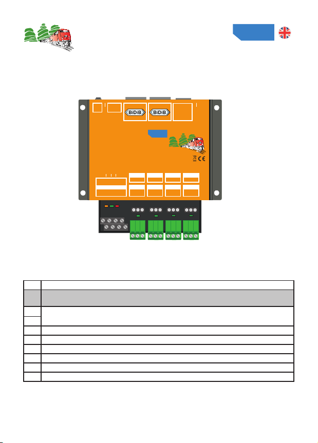
04. Connecng the ReadyServoTurn
WEEE-Reg.-Nr.DE52732575
FichtelBahn
ReadyServoTurn
4-fach BiDiB-Servodecoder
with 4x Relais and 4x Input
Line
Ready
Made in Germany
Power
12V - 18V
DC
ŝŝͲ/ĚĞŶƟĨLJ
TERM
DCC BiDiB
ĐƟǀŝƚLJ
POWER - ON
+-
TAST
ID
Message
REL 3REL 2REL 1
NO
REL 0
NC
COM
Servo 3
-D
+
INPUT
2
GND
2
Data
0
GND
0
Data
3
GND
3
Data
1
GND
1
Data
Servo 2
-D
+
Servo 1
-D
+
Servo 0
-D
+
NO NC
COM
NO NC
COM
NO NC
COM
Error
REL 3REL 2
REL 1REL 0
SERV 2 SERV 3
SERV 1
SERV 0
IN1 IN3
IN0 IN2
AB1 B2
C DH
LK
M
AConnector for the power supply (DC 12V-18V)
B BiDiB interface
connecon to command staon and further BiDiB nodes
B1 Both sockets are internally connected and can be used equally
B2
CTerminang jumper for terminang DCC signal
DTerminang jumper for terminang BiDiB
HIdent- / Bootloader buon for system funcons
K4x inputs against ground (e.g. for posion feedback of the servo motors)
L 4x servo outputs for servo motors
M4x relay outputs (changeover contact - NO/COM/NC) e.g. for frog polarisaon

Manual ReadyServoTurn © 2022 FichtelBahn®
Manual Version 1.0 Technical changes and errors reserved
Page 6
FichtelBahn
Line
Ready
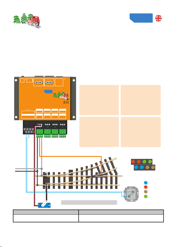
Connect the power supply terminal (A) of the module to a switched 12V-18V DC
power supply. Be careful to check the polarity of the module – marked red (+) and
blue (-) in the sketch.
04.1 Connecng the power supply
12V-18V
DC
WEEE-Reg.-Nr.DE52732575
FichtelBahn
ReadyServoTurn
4-fach BiDiB-Servodecoder
with 4x Relais and 4x Input
Line
Ready
Made in Germany
Power
12V - 18V
DC
ŝŝͲ/ĚĞŶƟĨLJ
TERM
DCC BiDiB
ĐƟǀŝƚLJ
POWER - ON
+-
TAST
ID
Message
REL 3REL 2REL 1
NO
REL 0
NC
COM
Servo 3
-D
+
INPUT
2
GND
2
Data
0
GND
0
Data
3
GND
3
Data
1
GND
1
Data
Servo 2
-D
+
Servo 1
-D
+
Servo 0
-D
+
NO NC
COM
NO NC
COM
NO NC
COM
Error
REL 3REL 2
REL 1REL 0
SERV 2 SERV 3
SERV 1
SERV 0
IN1 IN3
IN0 IN2
The current consumpon of up to max. 2A, depending
on the simultaneously acve servo motors, should be
taken into account when selecng the power supply.
Several modules can be connected to one power
supply at the same me if the power supply used can
provide the necessary output current.
Please noce:
DO NOT connect a transformer (alternang volt-
age/AC) or reced alternang voltage. Doing so
will lead to unrepairable damage to the module!
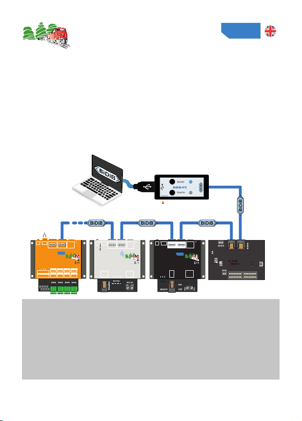
04.2 Connecng to the BiDiBus
The ReadyServoTurn has two parallel BiDiBus sockets (B1/B2) which can be used to
place the module at any desired posion within the bus by using patch cables. .
WEEE-Reg.-Nr.DE52732575
FichtelBahn
ReadyServoTurn
4-fach BiDiB-Servodecoder
with 4x Relais and 4x Input
Line
Ready
Madein Germany
Power
12V - 18V
DC
ŝŝͲ/ĚĞŶƟĨLJ
TERM
DCC BiDiB
ĐƟǀŝƚLJ
POWER- ON
+-
TAST
ID
Message
REL 3REL 2REL1
NO
REL 0
NC
COM
Servo 3
-D
+
INPUT
2
GND
2
Data
0
GND
0
Data
3
GND
3
Data
1
GND
1
Data
Servo 2
-D
+
Servo 1
-D
+
Servo 0
-D
+
NO NC
COM
NO NC
COM
NO NC
COM
Error
REL3REL2
REL1REL0
SERV2 SERV3
SERV1
SERV0
IN1 IN3
IN0 IN2
+
DCC1
DCC2
DCC1
DCC2
12V DC IN
DCC IN
16fach RailCom -Belegtmelder
GBM16TS
BiDiBConnect
PROG
POWER
J2/ TERM DCC
J3/ TERM BiDiB
DCC
RailCom
0
0
7
7
8
8
15
15
J5/ Power-Bus
PDI
REV
IDENT
WEEE-Reg.-Nr.DE52732575
FichtelBahn
ReadyBoost
BiDiBus DCC-Booster 4A
Line
Ready
Madein Germany
Power
12V - 18V
DC
ŝŝͲ/ĚĞŶƟĨLJ
TERM
DCC BiDiB
Message
POWER- ON
+ -
TAST
ID
EXT.
STOP
DCCInput
Overloadcurrent
DCC OUT
max.4A
DCC2 DCC1
BoosterON
BoosterOFF
DCC1
DCC2
STATE
DCCEXT.STOP
37
2
5ED
.
r
N
-.geR-EE
E
W 57
5
2
FichtelBahn
RF-Basis V2.0
Madein Germany
TERM
DCC BiDiB
DCC Input
TAST
ID
XpressNet
Message
BiDiB Input
XP Input
DCC IN
DCC1 DCC2
OpenCar-System
+ -
POWER- ON
Power
12V - 18V
DC
DCC1 DCC 2
MSG DCC IN
XpressNet
DCC BiDiB XP
InputSource
Abschluss-Jumper
setzen
... bis zu 32 Teilnehmer
XX
X
* ... Abschluss-Jumper intern gesetzt
Manual ReadyServoTurn © 2022 FichtelBahn®
Manual Version 1.0 Technical changes and errors reserved
Page 7
FichtelBahn
Line
Ready
Please noce:
If the rst and last module of the bus are not terminated with the terminaon
jumpers the distoron of the signal might lead to errors in the data transmission.
If the terminaon jumper is ed on a module within the bus the transmission
might be disrupted. Both cases will not lead to any damage of the modules.
In the previous gure, the module is placed within the BiDiBus. Therefore, no termina-
on jumper ( X terminaon) needs to be ed on the ReadyServoTurn. (For further
informaon on the subject of terminaon of the BiDiBus, please refer to chapter “08.
Background knowledge” on page 32.) A BiDiB-IF2 is shown as symbolic interface for
any type (e.g. GBM Master / GBMboost Master)..
In the following gure, the ReadyServoTurn was placed as the last module of the
BiDiBus. In this case, the two terminang jumpers for the BiDiB and DCC terminaon
must be ed on the module.
37
2
5ED
.
r
N
-.geR-EE
E
W 57
5
2
FichtelBahn
RF-Basis V2.0
Made in Germany
TERM
DCC BiDiB
DCC Input
TAST
ID
XpressNet
Message
BiDiB Input
XP Input
DCC IN
DCC1 DCC2
OpenCar-System
+ -
POWER- ON
Power
12V - 18V
DC
DCC 1 DCC 2
MSG DCC IN
XpressNet
DCC BiDiB XP
Input Source
+
DCC 1
DCC 2
DCC 1
DCC 2
12V DC IN
DCC IN
16fach RailCom -Belegtmelder
GBM16TS
BiDiBConnect
PROG
POWER
J2/ TERM DCC
J3/ TERM BiDiB
DCC
RailCom
0
0
7
7
8
8
15
15
J5/ Power-Bus
PDI
REV
IDENT
WEEE-Reg.-Nr.DE52732575
FichtelBahn
ReadyBoost
BiDiBus DCC-Booster 4A
Line
Ready
Made in Germany
Power
12V - 18V
DC
ŝŝͲ/ĚĞŶƟĨLJ
TERM
DCC BiDiB
Message
POWER- ON
+ -
TAST
ID
EXT.
STOP
DCC Input
Overloadcurrent
DCC OUT
max. 4A
DCC2 DCC1
BoosterON
BoosterOFF
DCC 1
DCC 2
STATE
DCCEXT.STOP
WEEE-Reg.-Nr.DE52732575
FichtelBahn
ReadyServoTurn
4-fach BiDiB-Servodecoder
with 4x Relais and 4x Input
Line
Ready
Made in Germany
Power
12V - 18V
DC
ŝŝͲ/ĚĞŶƟĨLJ
TERM
DCC BiDiB
ĐƟǀŝƚLJ
POWER- ON
+-
TAST
ID
Message
REL 3REL 2REL 1
NO
REL 0
NC
COM
Servo 3
-D
+
INPUT
2
GND
2
Data
0
GND
0
Data
3
GND
3
Data
1
GND
1
Data
Servo 2
-D
+
Servo 1
-D
+
Servo 0
-D
+
NO NC
COM
NO NC
COM
NO NC
COM
Error
REL 3REL 2
REL 1REL 0
SERV 2 SERV3
SERV 1
SERV 0
IN1 IN3
IN0 IN2
Abschluss-Jumper
setzen
... bis zu 32 Teilnehmer
XX
X
* ... Abschluss-Jumper intern gesetzt

Manual ReadyServoTurn © 2022 FichtelBahn®
Manual Version 1.0 Technical changes and errors reserved
Page 8
FichtelBahn
Line
Ready
04.3 Connecng a servo
Four servo motors can be connected
to the ReadyServoTurn for isolated
applicaons, but also in combinaon
with the relay outputs and the inputs
of the module.
Switch o servos aer movement:
The servos can be de-energised aer
the switching process. This oponal seng
avoids a possible servo hum. This seng can
be acvated individually for each servo in
the “Servo ports” secon.
Please noce:
It is recommended to keep the cable length between the module and the servo
short for safe operaon. Cable lengths exceeding 2 metres should always be
avoided.
In the FichtelBahn-Shop you will nd a 50cm servo cable extension with the arcle
no. 000830.
WEEE-Reg.-Nr.DE52732575
FichtelBahn
ReadyServoTurn
4-fach BiDiB-Servodecoder
with 4x Relais and 4x Input
Line
Ready
Made in Germany
Power
12V - 18V
DC
ŝŝͲ/ĚĞŶƟĨLJ
TERM
DCC BiDiB
ĐƟǀŝƚLJ
POWER - ON
+-
TAST
ID
Message
REL 3REL 2REL 1
NO
REL 0
NC
COM
Servo 3
-D
+
INPUT
2
GND
2
Data
0
GND
0
Data
3
GND
3
Data
1
GND
1
Data
Servo 2
-D
+
Servo 1
-D
+
Servo 0
-D
+
NO NC
COM
NO NC
COM
NO NC
COM
Error
REL 3REL 2
REL 1REL 0
SERV 2 SERV 3
SERV 1
SERV 0
IN1 IN3
IN0 IN2
Servo 0 bis Servo 3
Belegung Servo-Port
GND 5V Data
Wiring length:
The servo motors are controlled with a PWM signal that can interfere with other
consumers if the cables are long. Long cable lengths also lead to signal distorons that
can be noced by a twitching servo.
Moon prole
The module has 4 dierent moon proles
to choose from, which can be selected for
each movement direcon and for each servo in the sengs of the “Servo ports”.
There is a “so movement” for turnout drives and “rocking or kickback” for signals or
level crossings.

Manual ReadyServoTurn © 2022 FichtelBahn®
Manual Version 1.0 Technical changes and errors reserved
Page 9
FichtelBahn
Line
Ready
Please noce:
The overcurrent and short-circuit detecon is designed for a connuous load of
500mA / peak = 1A for each servo port.
WEEE-Reg.-Nr.DE52732575
FichtelBahn
ReadyServoTurn
4-fach BiDiB-Servodecoder
with 4x Relais and 4x Input
Line
Ready
Made in Germany
Power
12V - 18V
DC
ŝŝͲ/ĚĞŶƟĨLJ
TERM
DCC BiDiB
ĐƟǀŝƚLJ
POWER - ON
+-
TAST
ID
Message
REL 3REL 2REL 1
NO
REL 0
NC
COM
Servo 3
-D
+
INPUT
2
GND
2
Data
0
GND
0
Data
3
GND
3
Data
1
GND
1
Data
Servo 2
-D
+
Servo 1
-D
+
Servo 0
-D
+
NO NC
COM
NO NC
COM
NO NC
COM
Error
REL 3REL 2
REL 1
REL 0
SERV 2 SERV 3
SERV 1
SERV 0
IN1 IN3
IN0 IN2
Servo 0 bis Servo 3
Belegung Servo-Port
GND 5V Data
04.3.1 Servo protecon mechanisms
The ReadyServoTurn is designed for operaonal safety
with monitoring funcons.
Each servo output has overcurrent and short-circuit
detecon, which switches o the aected servo output
in the event of a fault. The remaining servo outputs can
sll be used.
The error status (shut-o of a servo output) is signalled
by a stac red error LED on the module.
If a new servo control command is issued for the defecve
output, the control programme receives a message via the ac-
cessory feedback that the servo output could not be switched
and therefore the route is not locked.
The shut-o and error message can only be reset with a
power reset of the ReadyServoTurn.
Which servo is suitable - digital or analogue?
One major dierence is that a digital servo can move to its posion faster and hold the
posion more accurately. An analogue servo uses an ohmic potenometer that loses
its repeon accuracy with temperature chages (tolerance).
Both types of servo can be connected to the ReadyServoTurn.
In the case of an eect, the advantage of the digital servo might make a dierence. For
a turnout or other movements with a mechanical posioning spring and strain relief,
the tolerance is unimportant. Here a large travel distance should be chosen and servos
with metal gears should be used. In the FichtelBahn-Shop you will nd a reliable and
inexpensive soluon with the arcle no. 410100
Manual ReadyServoTurn © 2022 FichtelBahn®
Manual Version 1.0 Technical changes and errors reserved
Page 10
FichtelBahn
Line
Ready
04.4 Connecng a relay output
04.5 Connecon inputs
WEEE-Reg.-Nr.DE52732575
FichtelBahn
ReadyServoTurn
4-fach BiDiB-Servodecoder
with 4x Relais and 4x Input
Line
Ready
Made in Germany
Power
12V - 18V
DC
ŝŝͲ/ĚĞŶƟĨLJ
TERM
DCC BiDiB
ĐƟǀŝƚLJ
POWER - ON
+-
TAS T
ID
Message
REL 3REL 2REL 1
NO
REL 0
NC
COM
Servo 3
-D
+
INPUT
2
GND
2
Data
0
GND
0
Data
3
GND
3
Data
1
GND
1
Data
Servo 2
-D
+
Servo 1
-D
+
Servo 0
-D
+
NO NC
COM
NO NC
COM
NO NC
COM
Error
REL 3REL 2
REL 1REL 0
SERV 2 SERV 3
SERV 1
SERV 0
IN1 IN3
IN0 IN2
DCC1
vom Belegtmelder
DCC2
vom Belegtmelder
DCC1
DCC1
POLARISIERT
DCC polarisiert
für Herzstück / Weichenzunge
1 2 3
1: Relais NO
2: Relais COM
3: Relais NC
NO = normally open
NC = normally closed
The ReadyServoTurn has 4 relay outputs (changeover contact) that can be used as a
isolated applicaon or with the servo motors and inputs.
The example illustraon
shows a frog polarisa-
on on relay output 0.
Alternavely, loads of up to
2A a connuous current per
relay can be switched with
the relay outputs.
The switched-on state of
the relay (1-NO connects
to 2-COM) is signalled by
the associated LED on the
module lighng up.
The ReadyServoTurn has 4 inputs against
ground potenal for pushbuons / sensors
for isolated applicaons or in combinaon with
the outputs of the module.
WEEE-Reg.-Nr.DE52732575
FichtelBahn
ReadyServoTurn
4-fach BiDiB-Servodecoder
with 4x Relais and 4x Input
Line
Ready
Made in Germany
Power
12V - 18V
DC
ŝŝͲ/ĚĞŶƟĨLJ
TERM
DCC BiDiB
ĐƟǀŝƚLJ
POWER - ON
+-
TAST
ID
Message
REL 3REL 2REL 1
NO
REL 0
NC
COM
Servo 3
-D
+
INPUT
2
GND
2
Data
0
GND
0
Data
3
GND
3
Data
1
GND
1
Data
Servo 2
-D
+
Servo 1
-D
+
Servo 0
-D
+
NO NC
COM
NO NC
COM
NO NC
COM
Error
REL 3REL 2
REL 1REL 0
SERV 2 SERV 3
SERV 1
SERV 0
IN1 IN3
IN0 IN2
Sensor
Taster / Schalter
DATA|GND
DATA|GND
1 | 2
3 | 4
Input 0
Input 1
Input 2
Input 3
Possible applicaons:
- Posion status of a servo with the aid of a
Hall sensor or reed contact
- connected pushbuons can trigger a
servo movement and/or relay changeover.
Please noce:
The inputs may only be connected to the module ground. Connecng an input to the system or another
power supply will result in a short circuit that may damage the module.

Manual ReadyServoTurn © 2022 FichtelBahn®
Manual Version 1.0 Technical changes and errors reserved
Page 11
FichtelBahn
Line
Ready
05. Conguraon of the module
The BiDiB-Wizard 2 is a Java program for displaying and conguring the BiDiB modules
on the BiDiBus. The current version BiDiB-Wizard 2 is available for free download in
our BiDiB-Wiki at hps://wiki.chtelbahn.de (in the overview tree under „Programme für BiDiB“
/ „BiDiB-Wizard“).
The BiDiB interface (BiDiB-IF2 or GBMboost Master) is connected to the computer
through a virtual serial port (USB). To establish a connecon the correct serial port (3.)
has to be selected under Edit (1.)/ Preferences (2.). In the drop down menu the cor-
rect Serial port has to be selected.
05.1 Establishing a connecon to the BiDiBus
Please noce:
Only one program can access an acve serial port simultaneously. If the railway controlling program is
using the serial port this connecon has to be terminated before the BiDiB-Wizard can make use of the
serial port.
Please noce:
The new automated BiDiB node congurator for this ReadyLine module is only available with the new
BiDiB Wizard 2 version.
The Wizard version 1 is also compable with this module, but only the classical macro programming is
available.
When using a BiDiB-
Ethernet
interface, e.g. IFnet,
you will need the
IP address of your
interface.

Manual ReadyServoTurn © 2022 FichtelBahn®
Manual Version 1.0 Technical changes and errors reserved
Page 12
FichtelBahn
Line
Ready
By clicking on the buon with the plug symbol (4.) the connecon will be iniated and
all connected nodes will be loaded and shown in the node tree view (5.).
By double clicking on a node in the node tree view (5.) this node will be loaded and its
funcons und opons will be shown in the node detail window (6.).
Window Descripton
Acons Update rmware
With this buon the rmware can be updated (see Firmware Update on page 33)
Acons BiDiB Node Congurator
Applicaon examples can be loaded via this buon. (see pageSeite 33 13)
Window Descripton
Acons Update rmware
With this buon the rmware can be updated (see Firmware Update on page 33)
Info Technical informaon about the module
Accessories Assigning and tesng the individual switching outputs or servo outputs, check the feedback indicaon.
Macros Memory locaons for each individual acon, using the macro step chain
Switch ports 4 relay outputs for switching their states ON / OFF
Servo ports 4 servo outputs and their control characteriscs, posion up / down, speed
Flags Visualisaon of internal ags for macro programmings
CV Denions Reading and wring of module specic CV sengs (see Module sengs on page 29)
2. Individual macro conguraon - for experienced users
....congure the applicaon according to your own wishes individually with the help of the macros.
For the “ReadyServoTurn” module, there are two ways of achieving an operaonal
state:
1. Easy to use - Node congurator for beginners
... easy and fast with with a simple and intuive user interface “BiDiB Node Congurator”.
standard use cases are set up automacally.

Manual ReadyServoTurn © 2022 FichtelBahn®
Manual Version 1.0 Technical changes and errors reserved
Page 13
FichtelBahn
Line
Ready
05.2 Node Congurator
The node congurator is available for
simple applicaons, with the help of
which the module is automacally
congured.
Clicking on Acons / BiDiB Node Con-
gurator opens a wizard that guides
you through all sengs and queries.
In the following window you can
choose between the four main cat-
egories.
A detailed funconal descripon with a potenal
connecon diagram is described at the end of
this chapter.
05.2.1 Using the assistant
Category Applicaon examples
Turnouts 4x servo turnouts with / without frog polarisaon or with / without posion
feedback
Turnouts with external input 4x servo turnouts with/without frog polarisaon that can also be operated
via an external input
Doubleslip / three-way turnouts Idencal to the category “Turnouts” only with 2 drives on one turnout
Eect / Parts 4x individual servos and 4x individual relays
Classic BiDiB Node Congurator Congurator for own scripts (import of addional scenarios)
Aer selecng the basic category, the required
applicaon must be chosen.
e.g. only 4 servo motors
Please noce:
In addion to the congurator, the macros for a
customised conguraon can always be used. The
wizard automacally creates macros, which can be
changed aer compleon.

Manual ReadyServoTurn © 2022 FichtelBahn®
Manual Version 1.0 Technical changes and errors reserved
Page 14
FichtelBahn
Line
Ready
05.2.2 Servo sengs
The following sengs for servo 0 are examplary for all 4 servo motors.
The window is part of the wizard, but can also be displayed at any me via the “Servo
ports” tab.
Seng Explanaon
Servo name Field for entering a user-dened name
Speed Denion of the servo’s orbital speed
Trim value boom and top Denion of the working range of the rotary movement (down = 0% / up = 100%).
Key commands: down = arrow right and le / up = CTRL + arrow right and le)
Curve form boom and top Servo moon prole: Linear, So, Bounce, Rebound, User
Servo power o The servo is de-energised aer reaching the end posion.
This funcon prevents servo hum, but the servo loses its holding force.
Adjust desnaon value The 0% / 100% buons and the slider can be used to test the servo sengs.
Clicking on “Apply” is necessary for the seng to be applied!
Changes to the sengs are made locally and are not
yet saved on the module. These changes are only saved
on the module with a click on “Apply”. The “Desna-
on value” funcon test can only demonstrate the new
changes if they have been saved beforehand. The last
saved values can be read with “Revert”.
Manual ReadyServoTurn © 2022 FichtelBahn®
Manual Version 1.0 Technical changes and errors reserved
Page 15
FichtelBahn
Line
Ready
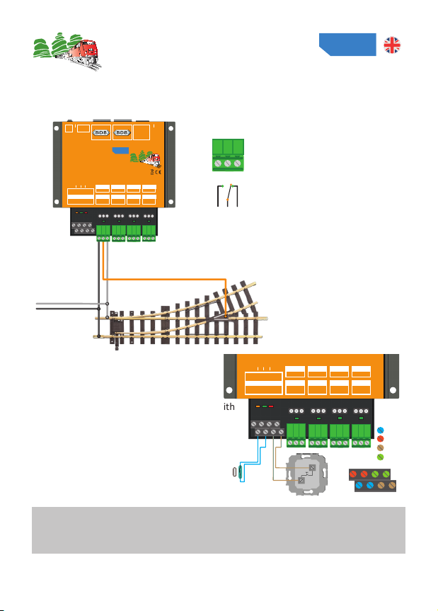
05.2.3 Servo with relay and feedback
In this set-up, the module can operate 1-4 servos, switch 1-4 relays and report back
the posion with the 4 inputs for each servo.
WEEE-Reg.-Nr.DE52732575
FichtelBahn
ReadyServoTurn
4-fach BiDiB-Servodecoder
with 4x Relais and 4x Input
Line
Ready
Made in Germany
Power
12V - 18V
DC
ŝŝͲ/ĚĞŶƟĨLJ
TERM
DCC BiDiB
ĐƟǀŝƚLJ
POWER - ON
+-
TAS T
ID
Message
REL 3REL 2REL 1
NO
REL 0
NC
COM
Servo 3
-D
+
INPUT
2
GND
2
Data
0
GND
0
Data
3
GND
3
Data
1
GND
1
Data
Servo 2
-D
+
Servo 1
-D
+
Servo 0
-D
+
NO NC
COM
NO NC
COM
NO NC
COM
Error
REL 3REL 2
REL 1REL 0
SERV 2 SERV 3
SERV 1
SERV 0
IN1 IN3
IN0 IN2
Abbildung exemplarisch für alle vier Ausgänge
DCC1
vom Belegtmelder
DCC2
vom Belegtmelder
DCC1
DCC1
POLARISIERT
DCC polarisiert
für Herzstück / Weichenzunge
Magnet
Sensor
Konfigura�on und Anschlusskonzept
DATA|GND
DATA|GND
1 | 2
3 | 4
Input 0
Input 1
Input 2
Input 3
Accessory 0
Begriff 0 Servo 0 = 0%
Relais 0 = OFF / DCC1
IN 0 = OFF
Begriff 1 Servo 0 = 100%
Relais 0 = ON/ DCC2
IN 0 = ON
Accessory 1
Begriff 0 Servo 1 = 0%
Relais 1 = OFF / DCC1
IN 1 = OFF
Begriff 1 Servo 1 = 100%
Relais 1 = ON/ DCC2
IN 1 = ON
Accessory 2
Begriff 0 Servo 2 = 0%
Relais 2 = OFF / DCC1
IN 2 = OFF
Begriff 1 Servo 2 = 100%
Relais 2 = ON/ DCC2
IN 2 = ON
Accessory 3
Begriff 0 Servo 3 = 0%
Relais 3 = OFF / DCC1
IN 3 = OFF
Begriff 1 Servo 3 = 100%
Relais 3 = ON/ DCC2
IN 3 = ON
Node congurator Applicaon examples
Turnouts • Servo, frog relay and sensor Servo turnout with frog polarisaon and posion feedback
The BiDiB Node Congurator sets up the macros and accessories according to this illustraon.
The servos, relay outputs and inputs must be connected in the same way.
Manual ReadyServoTurn © 2022 FichtelBahn®
Manual Version 1.0 Technical changes and errors reserved
Page 16
FichtelBahn
Line
Ready
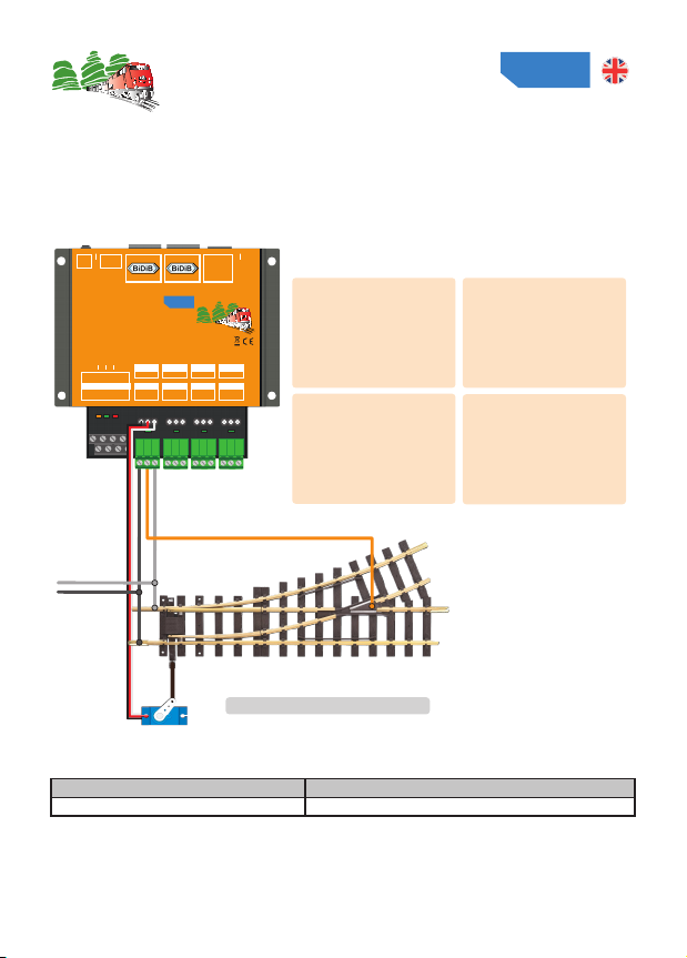
05.2.4 Servo with relay
WEEE-Reg.-Nr.DE52732575
FichtelBahn
ReadyServoTurn
4-fach BiDiB-Servodecoder
with 4x Relais and 4x Input
Line
Ready
Made in Germany
Power
12V - 18V
DC
ŝŝͲ/ĚĞŶƟĨLJ
TERM
DCC BiDiB
ĐƟǀŝƚLJ
POWER - ON
+-
TAS T
ID
Message
REL 3REL 2REL 1
NO
REL 0
NC
COM
Servo 3
-D
+
INPUT
2
GND
2
Data
0
GND
0
Data
3
GND
3
Data
1
GND
1
Data
Servo 2
-D
+
Servo 1
-D
+
Servo 0
-D
+
NO NC
COM
NO NC
COM
NO NC
COM
Error
REL 3REL 2
REL 1REL 0
SERV 2 SERV 3
SERV 1
SERV 0
IN1 IN3
IN0 IN2
Abbildung exemplarisch für alle vier Ausgänge
DCC1
vom Belegtmelder
DCC2
vom Belegtmelder
DCC1
DCC1
POLARISIERT
DCC polarisiert
für Herzstück / Weichenzunge
*Mechanik vereinfacht (siehe Handbuch)
Konfigura�on und Anschlusskonzept
Accessory 0
Begriff 0 Servo 0 = 0%
Relais 0 = OFF / DCC1
Begriff 1 Servo 0 = 100%
Relais 0 = ON/ DCC2
Accessory 1
Begriff 0 Servo 1 = 0%
Relais 1 = OFF / DCC1
Begriff 1 Servo 1 = 100%
Relais 1 = ON/ DCC2
Accessory 2
Begriff 0 Servo 2 = 0%
Relais 2 = OFF / DCC1
Begriff 1 Servo 2 = 100%
Relais 2 = ON/ DCC2
Accessory 3
Begriff 0 Servo 3 = 0%
Relais 3 = OFF / DCC1
Begriff 1 Servo 3 = 100%
Relais 3 = ON/ DCC2
Node congurator Applicaon examples
Turnouts • servo and frog relay Servo turnout with frog polarisaon
In this set-up, the module can operate 1-4 servos and switch 1-4 relays.
The BiDiB node congurator creates the macros and accessories according to this illustraon.
The servos and relay outputs must be connected in the same way..

Manual ReadyServoTurn © 2022 FichtelBahn®
Manual Version 1.0 Technical changes and errors reserved
Page 17
FichtelBahn
Line
Ready
05.2.5 Doubleslip / three-way turnout
WEEE-Reg.-Nr.DE52732575
FichtelBahn
ReadyServoTurn
4-fach BiDiB-Servodecoder
with 4x Relais and 4x Input
Line
Ready
Made in Germany
Power
12V - 18V
DC
ŝŝͲ/ĚĞŶƟĨLJ
TERM
DCC BiDiB
ĐƟǀŝƚLJ
POWER - ON
+-
TAS T
ID
Message
REL 3REL 2REL 1
NO
REL 0
NC
COM
Servo 3
-D
+
INPUT
2
GND
2
Data
0
GND
0
Data
3
GND
3
Data
1
GND
1
Data
Servo 2
-D
+
Servo 1
-D
+
Servo 0
-D
+
NO NC
COM
NO NC
COM
NO NC
COM
Error
REL 3REL 2
REL 1REL 0
SERV 2 SERV 3
SERV 1
SERV 0
IN1 IN3
IN0 IN2
Abbildung exemplarisch für 2 Doppelkreuzungsweichen
DCC1
vom Belegtmelder
DCC2
vom Belegtmelder
DCC1
DCC1
POLARISIERT
DCC polarisiert
für Herzstück / Weichenzunge
Magnet
Sensor
Konfigura�on und Anschlusskonzept
DATA|GND
DATA|GND
1 | 2
3 | 4
Input 0
Input 1
Input 2
Input 3
POLARISIERT
DCC1
DCC1
Doppelkreuzungsweiche 1 Doppelkreuzungsweiche 2
Accessory 0
Begriff 0 Servo 0 = 0%
Relais 0 = OFF / DCC1
IN 0 = OFF
Begriff 1 Servo 0 = 100%
Relais 0 = ON/ DCC2
IN 0 = ON
Begriff 2 Servo 1 = 100%
Relais 1 = ON/ DCC2
IN 1 = ON
Begriff 3 Servo 1 = 0%
Relais 1 = OFF/ DCC1
IN 1 = OFF
Accessory 1
Begriff 0 Servo 2 = 0%
Relais 2 = OFF / DCC1
IN 2 = OFF
Begriff 1 Servo 2 = 100%
Relais 2 = ON/ DCC2
IN 2 = ON
Begriff 2 Servo 3 = 100%
Relais 3 = ON/ DCC2
IN 3 = ON
Begriff 3 Servo 3 = 0%
Relais 3 = OFF/ DCC1
IN 3 = OFF
Node congurator Applicaon examples
Doubleslip• servo, frog relay and sensor Doubleslip or three-way turnouts with frog polarisaon and posion feedback
With this set-up, the module can operate 1-2 doubleslip / three-way turnouts with 2
servos each, switch 2 relays and report back their posion.
The BiDiB Node Congurator creates the macros and accessories according to this illustraon.
The servos relay outputs and inputs must be connected the same way.
Manual ReadyServoTurn © 2022 FichtelBahn®
Manual Version 1.0 Technical changes and errors reserved
Page 18
FichtelBahn
Line
Ready
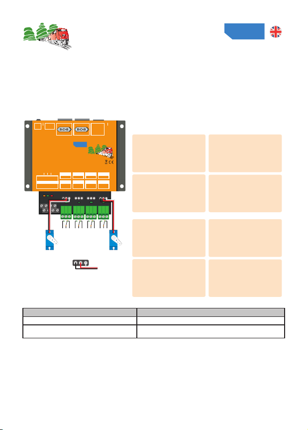
05.2.6 Servo and relay separated (eects)
WEEE-Reg.-Nr.DE52732575
FichtelBahn
ReadyServoTurn
4-fach BiDiB-Servodecoder
with 4x Relais and 4x Input
Line
Ready
Made in Germany
Power
12V - 18V
DC
ŝŝͲ/ĚĞŶƟĨLJ
TERM
DCC BiDiB
ĐƟǀŝƚLJ
POWER - ON
+-
TAS T
ID
Message
REL 3REL 2REL 1
NO
REL 0
NC
COM
Servo 3
-D
+
INPUT
2
GND
2
Data
0
GND
0
Data
3
GND
3
Data
1
GND
1
Data
Servo 2
-D
+
Servo 1
-D
+
Servo 0
-D
+
NO NC
COM
NO NC
COM
NO NC
COM
Error
REL 3REL 2
REL 1REL 0
SERV 2 SERV 3
SERV 1
SERV 0
IN1 IN3
IN0 IN2
Servo 0 bis Servo 3
Belegung Servo-Port
GND 5V Data
Konfigura�on und Anschlusskonzept
Accessory 0
Begriff 0 Servo 0 = 0%
Begriff 1 Servo 0 = 100%
Accessory 1
Begriff 0 Servo 1 = 0%
Begriff 1 Servo 1 = 100%
Accessory 2
Begriff 0 Servo 2 = 0%
Begriff 1 Servo 2 = 100%
Accessory 3
Begriff 0 Servo 3 = 0%
Begriff 1 Servo 3 = 100%
Accessory 4
Begriff 0 Relais 0 = OFF
Begriff 1 Relais 0 = ON
Accessory 5
Begriff 0 Relais 1 = OFF
Begriff 1 Relais 1 = ON
Accessory 6
Begriff 0 Relais 2 = OFF
Begriff 1 Relais 2 = ON
Accessory 7
Begriff 0 Relais 3 = OFF
Begriff 1 Relais 3 = ON
Servo 0-3:
Relais 0-3:
In this set-up, the module can move 1-4 servos and, separately, the relays 1-4. The
servos and the relays are divided between separate accessories 0-7.
The BiDiB Node Congurator creates the macros and accessories according to this illustraon.
The servos or relay outputs must be connected the same way.
Node congurator Applicaon examples
Eect / Parts • servo only Eect applicaons e.g. shed gates, waving pedestrians
Eect / Parts • Servo and relay separated Eect applicaons for servo movements and separate relay for switching
of loads
Manual ReadyServoTurn © 2022 FichtelBahn®
Manual Version 1.0 Technical changes and errors reserved
Page 19
FichtelBahn
Line
Ready
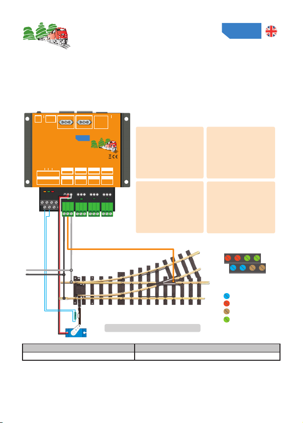
05.2.7 Input operates servo and relay
WEEE-Reg.-Nr.DE52732575
FichtelBahn
ReadyServoTurn
4-fach BiDiB-Servodecoder
with 4x Relais and 4x Input
Line
Ready
Made in Germany
Power
12V - 18V
DC
ŝŝͲ/ĚĞŶƟĨLJ
TERM
DCC BiDiB
ĐƟǀŝƚLJ
POWER - ON
+-
TAS T
ID
Message
REL 3REL 2REL 1
NO
REL 0
NC
COM
Servo 3
-D
+
INPUT
2
GND
2
Data
0
GND
0
Data
3
GND
3
Data
1
GND
1
Data
Servo 2
-D
+
Servo 1
-D
+
Servo 0
-D
+
NO NC
COM
NO NC
COM
NO NC
COM
Error
REL 3REL 2
REL 1REL 0
SERV 2 SERV 3
SERV 1
SERV 0
IN1 IN3
IN0 IN2
Abbildung exemplarisch für alle vier Ausgänge
DCC1
vom Belegtmelder
DCC2
vom Belegtmelder
DCC1
DCC1
POLARISIERT
DCC polarisiert
für Herzstück / Weichenzunge
Konfigura�on und Anschlusskonzept
DATA|GND
DATA|GND
1 | 2
3 | 4
Input 0
Input 1
Input 2
Input 3
Accessory 0
Begriff 0 oder Input 0 = 0
Servo 0 = 0%
Relais 0 = OFF / DCC1
Begriff 1 oder Input 0 = 1
Servo 0 = 100%
Relais 0 = ON/ DCC2
Accessory 1
Begriff 0 oder Input 1 = 0
Servo 1 = 0%
Relais 1 = OFF / DCC1
Begriff 1 oder Input 1 = 1
Servo 1 = 100%
Relais 1 = ON/ DCC2
Accessory 2
Begriff 0 oder Input 2 = 0
Servo 2 = 0%
Relais 2 = OFF / DCC1
Begriff 1 oder Input 2 = 1
Servo 2 = 100%
Relais 2 = ON/ DCC2
Accessory 3
Begriff 0 oder Input 3 = 0
Servo 3 = 0%
Relais 3 = OFF / DCC1
Begriff 1 oder Input 3 = 1
Servo 3 = 100%
Relais 3 = ON/ DCC2
Taster / Schalter
With this set-up, the inputs can also trigger the operaon of servo and relay in addi-
on to the accessory. With input state 0, the servo moves to the 0% posion. When
the state is changed to 1, the servo moves to 100% and switches the relay on. Aer
conguraon over the BiDiBus, the module can be used standalone (without BiDiBus
connecon).
The BiDiB Node Congurator sets up the macros and accessories according to this illustraon.
The servos, relay outputs and inputs must be connected the same way.
Node congurator Applicaon examples
Turnouts • servo, frog relays and inputs Input operates servo with frog polarisaon e.g. external control panel or push-
buon at the edge of the layout / manual control

Manual ReadyServoTurn © 2022 FichtelBahn®
Manual Version 1.0 Technical changes and errors reserved
Page 20
FichtelBahn
Line
Ready
05.3 Manual Conguraon
In addion to the predened conguraons provided by the node congurator, you
can also create your own conguraons and sequences using the macros and acces-
sories.
Please noce:
With the manual conguraon even conguraons created by the Node
Congurator can be amended.
Correlaon of output, input, macros and ac-
cessories:
The specic parameters of the outputs and
inputs can be dened in the hardware sengs
(servo, switching outputs and inputs).
These ports are linked in the macros as se-
quences and thus result in the desired eect,
movement sequence or switching process.
A macro describes the sequence of an ac-
cessory aspect: e.g. servo movement from
turnout posion “straight” to turnout posion
“diverging”.
Accessories
Makro Makro
Servo Relais Input
Example:
A turnout with two aspects has 2 macros. A signal with seven aspects has 7 individual
macros.
The top level accessory is the linking element and creates the link between aspects
and an acon. This link is called an accessory and can be controlled by the control
program.
In the following chapters, the individual windows (Ports, Macro and Accessory) are
explained in more detail, with the example applicaon “Servo, Relay and Feedback”
from the Node Congurator. For other applicaons, individual steps can be omied or
congured dierently.
Table of contents
Other Fichtelbahn Media Converter manuals


