Fichtelbahn OpenDCC BiDiB LightControl V1.3 User manual

LightControl V1.3
„Manual for SMD pre fitted kit”
Manual to build the SMD pre fitted Hardware manual-Version V1.4-en
page 1

Table of contents
Introduction......................................................................................................... 3
1. LightControl: .................................................................................................... 7
2. Construction description of the SMD equipped board:..................................... 9
Step 1: the power supply............................................................................................................................ 9
step 2: „function test bootloader“ ........................................................................................................... 10
Step 3: BiDiB-interface ............................................................................................................................. 10
step 4: 16 Power outputs and 8 inputs ..................................................................................................... 11
step 5: 32x LED-outputs: ........................................................................................................................... 11
step 6: 4x servo-outputs:........................................................................................................................... 12
3. The firmware update...................................................................................... 13
3.1 Approach with the firmware update............................................................................................. 13
4. Status announcements................................................................................... 15
5. References ..................................................................................................... 17
Manual to build the SMD pre fitted Hardware manual-Version V1.4-en
page 2

Introduction
These instructions refer to the BiDiB / DCC decoder "LightControl " from OpenDCC and Fichtelbahn.
The decoder gets on not as a commercial ready product, but is a development aid or kit for technically interested
railroad modeler for the own construction.
Here once again a clear tip:
The decoder and these instructions were checked carefully and provided after the best knowledge. For the
information presented here no claim to completeness, actuality, quality and correctness is raised. No responsibility for
the damages which originate from the trust in the contents of these instructions, to the decoder or their use can be
taken over.
The software of the decoder can be downloaded on our Internet site , may be extended by everybody uses, and be
improved.
A commercial use of the software or parts from it are not permitted!
Warranty
The use of this manual is permitted only for the reproduction and the personal use of the described stone. An other use
needs the written approval of the author.
For the reproduction and its functions of the described stone the author assumes no liability.
The operator is responsible for the observance of existing regulations and the regular use of the product alone.
Reference:
RailCom® and RailComPlus® are regisrtered trademarks
of Lenz Elektronik GmbH and
ESU electronic Solutions Ulm GmbH & Co. KG.
for the rise of the legibility of the text have we refuses to refer by every use of the concept to it.
Manual to build the SMD pre fitted Hardware manual-Version V1.4-en
page 3

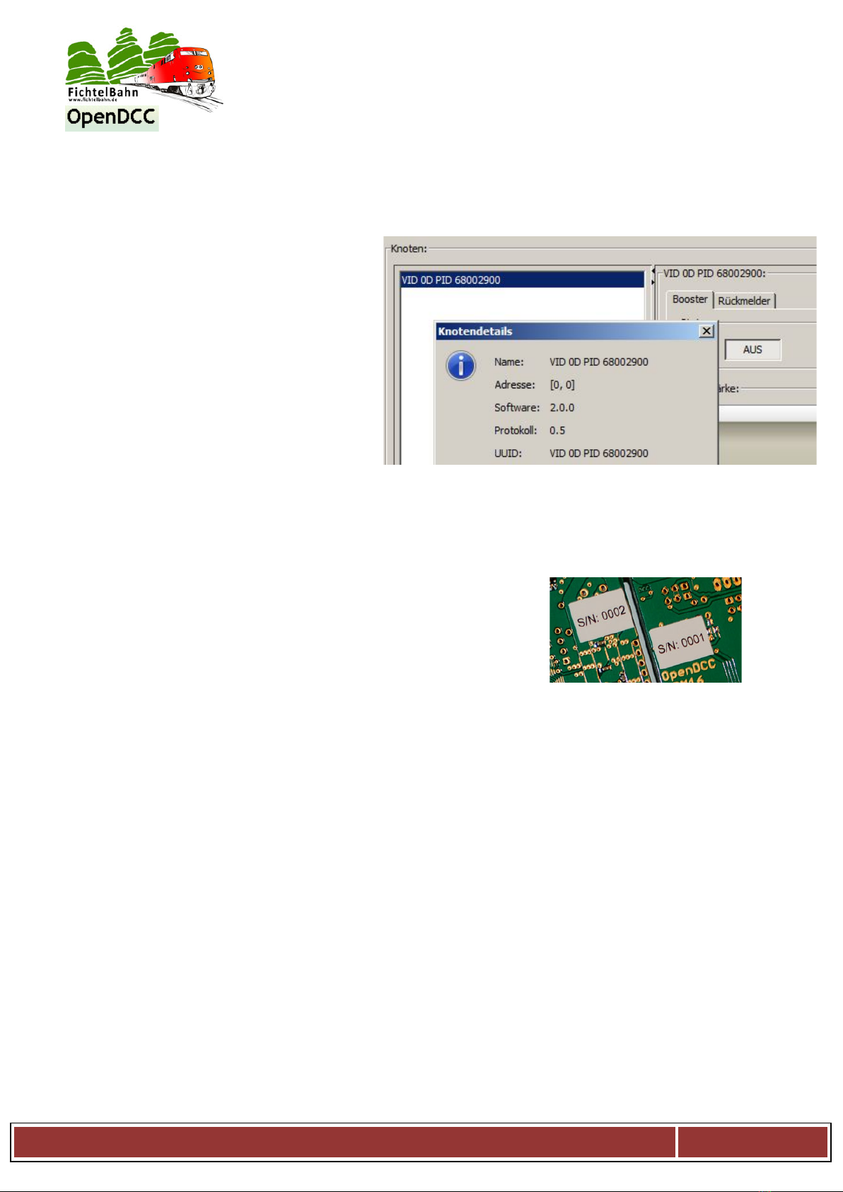
Interesting facts to the BiDiB-Seriennummer / Unique-ID
The picture shows a Unique-ID on a BiDiBus
Device.
All SMD equipped BiDiB assemblies bought from the
Fichtelbahn shop and are on the BiDiBus will be
delivered with an installed BiDiB-serialnumber. This
srialnumber is part of the unique-ID and therefore the
complete unique ID is printed at the back side of the
cuircuit.
What is the Unique-ID?
The from the manufacturer in the kit hard programmed, unequivocal ID, consisting of 16 Bit vendor ID and
32 Bit vendor specific number (e.t. produktindex and serialnumber).
V= VID (Vendor ID)
OD = Do it your self projects
P= PID (product ID)
6800 = GBMboost Master
6700 = GBMboost Node
6B00 = LightControl
0029 becomes to 2900 = serialnumber
The data of the Unique-ID are in HEX.
For what serves the Unique ID?
The Unique-ID is an absolutely unique number, with this number an assembly is found regardless of its
installation place and its place in the bus.
That means: The BiDiB system leads a sort of 'phone book', under which connection which assembly can
be reached. Then the hostprogram awards names for the single connections. The Unique-ID is here the
connector between the name in the PC and the assembly.
Example:
A LightControl is omounted under the railway station and has the Unique-ID 0D 6B001234. In the
Hostprogramm it is called central station west. The BiDiB system announces to the Hostprogramm:
0D6B001234 you find under connection 3. If one moves something now in central station west, the
Hostprogramm looks in the phone book: ah, I should call 3.
You have normally nothing more to do with addresses and dip switches.
Manual to build the SMD pre fitted Hardware manual-Version V1.4-en
page 4
Why should I stick on this number?
For what could I use this information?
All tools, however, also the actual PC-
hostprogramms communicate and
administer the assemblies with this
number. Now there is no more "address
DCC XX", but the cmmand is sent into the
knots *Unique-ID X* and his port.
The reverse is that for the configuration of
a new action at the output of a decoder
(e.g., LightControl) or the allocation of a
dispatch rider in the rail picture (e.g.,
GBM), the program must be informed
about the suitable Unique-ID of the BiDiB
assembly.
Hardware-serialnumber:
The stuck serialnumber with S/N at the back of the assembly is a hardware-
serialnumber and nothing deals with the Unique-ID serialnumber for the
BiDiB assemblies. With this number your assembly is registered with us.
Where is the Unique-ID stored on the assembly?
Here the procedure is bipartite a little bit. In the Flash/EEPROM-firmware file the VID and PID are already
integrated and are transmitted to the sassembly, however, no serialnumber is included. Hence, the
firmware files can be loaded easily in the processor or can be also updated. Besides, an already available
serialnumber will not be overwritten. If the sassembly still recognises no loaded serialnumber while
starting, a error code flashes and the use of the assembly is blocked.
Without serialnumber the firmware does not run!
(Exception with the master GBMboost: here a Notfall-S/N is generated with the sign: 0100. These S/N can
be overwritten any time with the upload of the valid S/N)
The serialnumber is always postpushed as the third act of the introduction and lands as first in the
EEPROM of the assembly.
Manual to build the SMD pre fitted Hardware manual-Version V1.4-en
page 5

By every new start the appliance explains the following examination:
He looks in the user signature area whether already a serialnumber exists.
If no serialnumber is available here the serialnumber from the EEPROM is filed and the assembly begins
starts to work. If there is in the USERS signature area already a serialnumber available the new-struck up
serialnumber is rejected by the EEPROM and the already deposited serialnumber from the user signature
area is used.
The deposited serialnumber in the USER signature area is also preserved with a CHIP ERASE and can be
deleted only with a USER signature ERASE.
If you must change the serialnumber on a BiDiBus suited Device, it works only with a previous USER
signature ERASE.
However, this also entails that available calibration values get lost because these are also stored in this area.
This should not be done without a special reason.
I have deleted the printed serialnumber by mistake.
How can this be uploaded again?
1. You load a new serialnumber with the generator and upload this after deleting the USER signature area
to the BiDiBus Device.
Importantly: Now do not forget to replace the existing sticker by the new Unique-ID. Link to to the
generator: http://www.opendcc.de/elektronik/bidib/opendcc_bidib.html
2. You want to use the available (printed) Unique-ID again because it was already deposited in the rail
trackplans of my PC programms.
In this case contact Fichtelbahn-Support with the information of the printed Unique-ID number and
the accompanying hardware-serialnumber.
This works only with preequipped SMD kits! With independently loaded serialnumbers you must look in
the history of your loaded serialnumbers in the generator, for the suitable number.
Manual to build the SMD pre fitted Hardware manual-Version V1.4-en
page 6

1. LightControl:
a. electrical parameters / functions
- Switch regulator with 3A source management
- 16 freely programmable switch exits with 300 mA each
-32 LED exits with adjustable stream spring and brightness regulation about PWM
- 4 Servo outputs, electricity supply of the Servo switchable
-8 universally Inputs
- BiDiBus- interface
-Universal port for USB (FTDI)
- Board size: 80mm x 100mm
b. partlist
base version:
(power supply, processor and system parts):
1x L1 SLF12575 33µH SMD-coil
1x D9 SSA33L SMD-diode
2x C37, C38 15pF / 0603 SMD-capacitor
4x D60, D70,
D80, D90 1N4007 rectifier diode
4x LED5-LED8 LED-0603 yellow, red, green LED
1x RN8 BCN16 1,0kOhm SMD-Parallelwiderstand
14x C3,C6,C16,C17
C24,C25,C34
C35,C27-C32 100nF / 0603 SMD-capacitor
1x C4 470µF/ 25V Panasonic_G electrolytic capacitor
1x C8 220µF/ 10V Panasonic_D electrolytic capacitor
1x C5 220µF/ 10V Panasonic_D electrolytic capacitor
1x C33 220µF/ 10V Panasonic_D electrolytic capacitor
1x IC1 LM2596DSADJR4G switching regulator 3A
1x IC4 LP2951CMX-3.3 voltage regulator 3,3V
1x IC7 ATXMEGA128A1Umicrocontroller
1x Q1 HC49-SMD 8MHz quartz
1x F1 1812L PTC Sicherung PTC fuse
1x S1 Taster 9314 SMD -button
1x Jumper 2,54 SW Jumper
1x SL 1x36G 2,54 pin row
1x X2 AKL055-03 terminal strip 3pole
1x R37 1,1kOhm 0805 SMD-resistor
1x R38 3,3kOhm 0805 SMD-resistor
Manual to build the SMD pre fitted Hardware manual-Version V1.4-en
page 7

upgrade servo:
1x R24 10kOhm 0603 SMD-resistor
1x RN5 BCN16 1,0kOhm SMD-parallel resistor
1x RN3 BCN16 100Ohm SMD-parallel resistor
1x R5 1Ohm 1206 resistor
1x C19 220µF/ 10V Panasonic_D electrolytic capacitor
4x C1, C2, C7, C9 47µF / 6 1206 capacitor
1x C14 100nF / 0603 SMD-capacitor
1x IC8 74VHCT 541D buffer
4x Q2, Q4, Q5, Q6 IRLML 5203 MosFet-transistor
1x JP9 Jumper jumper
1x SL 1x20G 2,54 pin row
upgrade power-output:
2x IC2, IC6 ULN2803 driver
2x SV1, SV2 WSL16G Wannenstecker 16pol
upgrade LED-output:
2x R34, R36 10k Poti SMD SMD-Poti
2x U$1, U$2 TLC5941 LED-driver
2x R33, R35 1kOhm 0603 SMD-resistor
2x C22, C23 100nF 0603 SMD-capacitor
2x SV3, SV4 WSL 34G Wannenstecker 32pol
upgrade input:
1x SV5 WSL16G Wannenstecker 16polig
2x RN1, RN2 BCN16 1,0kOhm SMD-parallel resistor
upgrade BiDiB-interface:
2x X8, X9 MEBP 8-8G RJ45 socket
1x IC5 ISL83075EIBZA Transceiver
2x R7 10kOhm 0805 SMD-resistor
1x C10 100nF 0805 SMD-capacitor
Manual to build the SMD pre fitted Hardware manual-Version V1.4-en
page 8
2. Construction description of the SMD equipped board:
For the construction of the SMD of equipped board is not necessary much.
A soldering iron, with fine soldering tip, tin-solder and an ohm metre.
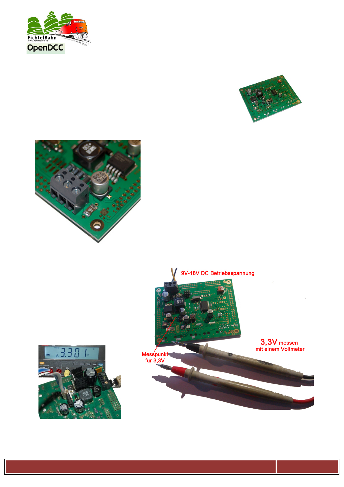
Step 1: the power supply
As the first we equip on the top of the board the 3-pole
connection clip X2.
With supply of the LightControl about an external source
(recommended) both solder jumpers SJ6 and SJ7 stay open. If the LC
about the tension DCC the both solder jumpers must be closed and X2
not equipped..
The LightControl can be supplied with DC voltage and AC voltage with
the help of the rectifier the suitable polarity always lies with the switch
regulator. Even if you supply the module with a DC voltage the rectifier
equipped remain, therefore receive a polarity protection.
important:Pay attention with this variation to the right polarity in the
clip X2 (X2-2 und X2-3).
The power supply for the light control is ready.
Check:
To test, the 3,3V a pin row can be
soldered at position J11. Now
3.3 V should be measurable here!
Follow the next section only
with successful tension
measurement!!
This picture has an insertion divergence, however, shows the measuring result!
Manual to build the SMD pre fitted Hardware manual-Version V1.4-en
page 9
step 2: „function test bootloader“
Switch on the LightControl (apply voltage) and afterwards you
press the button. Now the first red light-emitting diode must
shine!!
With this the micro controller unit is operational!
In the following steps the single functional exits are equipped:
comunication interfaces:
•BIDIB
functions:
•Inputs for internal functions and position indicators
•16x Power outputs for effects and magnetic
components
•4x servo-outputs
•32x LED-outputs
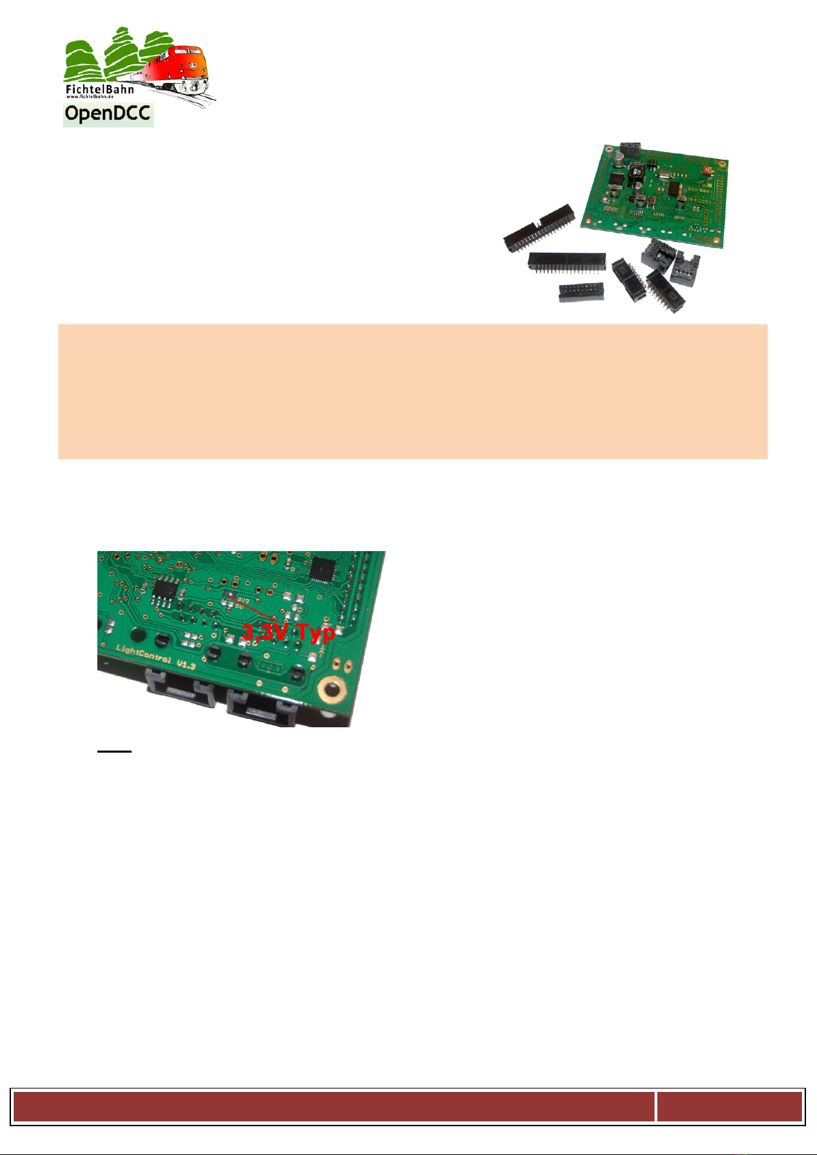
Step 3: BiDiB-interface
The BiDiB interface for adressless communication
consists of an RS-485 Transceiver.
important:
According to built-in RS-485 Transceiver both solder jumpers
must be closed differently.
In the SMD equipped version 3.3 V type is used!!
3,3V:
R10 (3,3V labeled) closed and R11 (5V labeled) open a ISL83075EIBZA is used
Both RJ45 sockets X8 and X9 are on the top the board. The board is prepared for a SMD or for a DIL
version. These both RJ45 sockets must be still equipped.
advice:
With a Hotplug function or an extensive BiDiBus wiring (e.g., gymnasium) we recommend one more
protective diode SM712 with to equip (not inevitably by small arrangements).
(available at the Fichtelbahn-Shop)
Manual to build the SMD pre fitted Hardware manual-Version V1.4-en
page 10
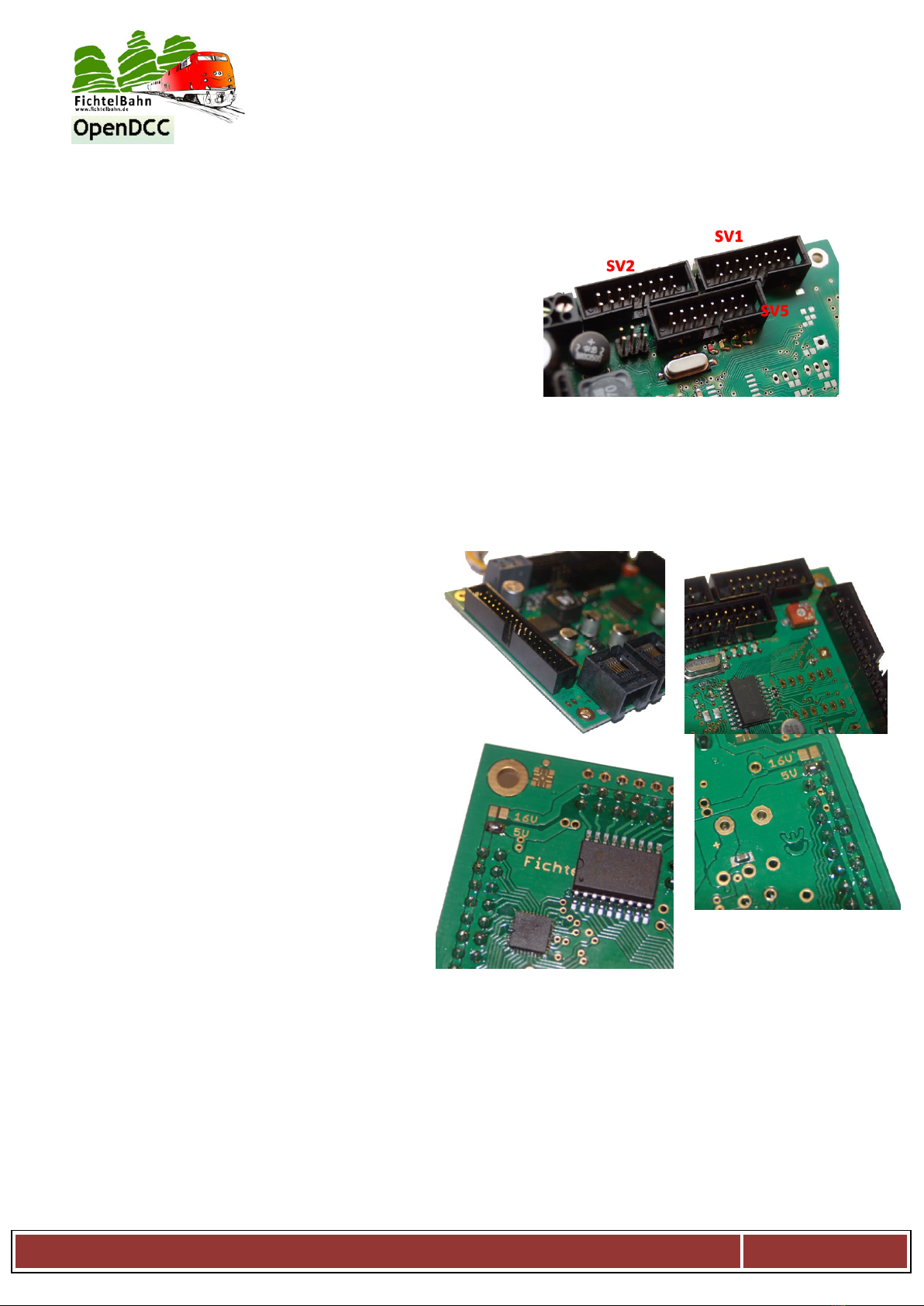
step 4: 16 Power outputs and 8 inputs
These 16 exits are suited for lighting effects with light bulbs,
also switch from bigger load max. to 300 mA per output or
for magnet articles.
For this the tub plugs SV2 and SV1 must be soldered for the
power outputs and SV5 for 8 inputs.
Please, follow the right installation direction
(see photo). With the tub plugs SV2 and SV1 the outer bore
row remains free!
step 5: 32x LED-outputs:
These 32 LED-outputs can be used for signal signs also for lighning effects.
With both Potis R34 and R36 you can change
the basic brightness of the respective driver
(power source).
The light-emitting diodes are connected in the
tub plugs SV3 and SV4. These must be still
soldered, besides, follow the right installation
direction (see photo)
Beside the tub plugs (bottom side) there are
still the solder jumpers SJ10, SJ11, SJ12
and SJ13, with it you can determine the
supply voltage for the LED.
We recommend for a supply without
dropping resistor 5 V of potential.
With several light-emitting diodes in row
per exit one needs 16 V variation.
Here the LEDs should be used with
dropping resistor.
Manual to build the SMD pre fitted Hardware manual-Version V1.4-en
page 11
step 6: 4x servo-outputs:
The 4 servo ports can be used for raiload effects also for
servo railroad switches.
To the usage of this function still five pin headers JP3, JP4,
JP5, JP6 and JP9 / J12 must be equipped on the top.
CAUTION: Short circuit danger:
With JP9 / JP12 5 V of Servo care can be impaled
externally or 5 V of supply be measured. For internal 5 V of
Servo supply the Pins 2 and 3 must be connected by a
jumper.
Manual to build the SMD pre fitted Hardware manual-Version V1.4-en
page 12

3. The firmware update
With the SMD equipped LightControl we have this already done for you! The LightControl is
completely ready for use with the actual Bootloader, the actual firmware and the printed
serialnumber.
The chapter „firmware update“ describes only the steps for the case of an update if a new firmware
is available for the LightControl!
In other cases (first introduction if still no firmware was uploaded)please read the programming
steps in the construction instructions of the soldering kit.
3.1 Approach with the firmware update
The LightControl can become beside the
Programmer also directly flashed with the BiDiB-
Wizard tool. This function should be also used at
a firmware update.
The advantage is:
The LightControl can be updated in the built-in
state with the tool, you also speaks of a distant
servicing.
In the knot list of the BiDiB-Wizard tool you find
your LightControl and all other BiDiB
components, for configuration or for a firmware
update.
Download the actual firmware for the
LightControl from our web page and ectract the
ZIP file on your PC.
Tip:
Use with an update only the file with the name:
lightcontrol_update…000.hex
With this all macro and settings remain you
have configured on the LightControl preserved
and are not overwritten by Default values
.
You must transfer only this file to the LightControl with the BiDiB-Wizard tool.
Both other files are the firmware files for the first introduction. By use your stored settings with the Default
values are overwritten (default settings).
Manual to build the SMD pre fitted Hardware manual-Version V1.4-en
page 13

Step 1:
The LightControl is connected to the care tension and is
also connected to the BiDiBus.
Step 2:
Open the BiDiB-Wizard tool and in the knot list the
serialnumber of the interface (master GBMboost) and
the LightControl should be visible.
Step 3:
With the right mouse key click on the serialnumber of
the LightControl and select in the pop-up menu the
action”Firmware Update”.
Step 4:
In the last step the folder must be selected in which the firmware file lightcontrol_update_xxxxxx.000.hex
is stored and this must be transferredWith close of the window the LightControl is updated to the new
firmware and is ready for operation.
Tip:
With an update of the LightControl only the special marked update ….001.hex file shoul be used,
otherwise all macro and port settings on the LightControl get lost. (default settings)
Manual to build the SMD pre fitted Hardware manual-Version V1.4-en
page 14

Bootloader
button S1 pressed?
yes
Demo-Jumper inserted?
no
Application forward
yes
FTDI Bootloader
no
BiDiB Bootloader
4. Status announcements
Demo-jumper:
The LightControl has a TEST SELF or DEMO with its activation all ports a run
light spend. With this function all ports of the LightControl can be tested.
Preparation:
Close the 2pole pin row JP2 with a Jumper.
Approach:
Connect the Lightcontrol to yout power
supply and connect the LED and Power
outputs to a luminous-medium. When closing
the DEMO Jumper. With close of the jumper
"DEMO jumper " a run light is given
regardless of the stored macros to the power
and LED exits.
So you can detect defect ports..
also EXTRA:
If you close one of the 8 inputs one of the power exits shines independent of the run light permanently up
to again open of the input. so you can also test the functionally of the inputs.
Important:
Don´t forget to open the „DEMO Jumper“ after the test, before you transfer a macro to the Lightcontrol.
Otherwise the DEMO mode macro will be deleted.
Key combination for Bootloader:
Manual to build the SMD pre fitted Hardware manual-Version V1.4-en
page 15

Errorcodes and statusleds:
red LED shines
LC is in Bootloader Mode
all LED´s flashing
LC has no EEPROM-File loaded
Yellow and green
LED flashing
LC has no serialnumber loaded
first green LED
shimmers
LC is ready
First green LED
shimmers, second
green LED shined
LC is ready and connected to BiDiB
Manual to build the SMD pre fitted Hardware manual-Version V1.4-en
page 16

5. References
The continuing instructions "introduction and use" deal with the following main
topics:
- Introduction
- Functionality of the macros
- Configutariontool "BiDiB-Wizard Tool"
- Debuginterface
- Application in connection with railroad software
- Firmware update
I am very grateful for improvement suggestions and tips to mistakes.
On the construction manual or any software there is no liability for any damages or functional guarantee.
I do not guarantee for damages which cause the user or third parties by the use of the software or hardware
or suffer. In no case I guarantee for escaped turnover or profit or other property damages by the use or by
the use of these programmes or instructions can originate.
With further inquiries our Support forum is available to you with pleasure!
(www.opendcc.de/forum)
contact:
fichtelbahn.de
Christoph Schörner
Ahornstraße 7
D-91245 Simmelsdorf
support@fichtelbahn.de
© 2014 Fichtelbahn
All rights, in particular the right of her
Duplication and spreading as well as
of the translation reserve.
Duplications and reproductions
in any form need her
written approval by Fichtelbahn.
Technical changes reserve.
Manual to build the SMD pre fitted Hardware manual-Version V1.4-en
page 17
Table of contents
Other Fichtelbahn Media Converter manuals


