McIntosh VP 1000 User manual

McIntosh Laboratory, Inc. 2 Chambers Street Binghamton, New York 13903-2699 Phone: 607-723-3512 FAX: 607-724-0549
VP1000
Owner’s Manual
Video Processor

2
The lightning flash with arrowhead,
within an equilateral triangle, is
intended to alert the user to the
presence of uninsulated “danger-
ous voltage” within the product’s
enclosure that may be of sufficient
magnitude to constitute a risk of
electric shock to persons.
1. Read these instructions.
2. Keep these instructions.
3. Heed all warnings.
4. Follow all instructions.
5. Do not use this apparatus near water.
6. Clean only with a dry cloth.
7. Do not block any ventilation openings. Install in
accordance with the manufacturer’s instructions.
8. Do not install near any heat sources such as radia-
tors, heat registers, stoves, or other apparatus
(including amplifiers) that produce heat.
9. Do not defeat the safety purpose of the polarized
or grounding-type plug. A polarized plug has two
blades with one wider than the other. A ground-
ing type plug has two blades and a third ground-
ing prong. The wide blade or the third prong are
provided for your safety. If the provided plug does
not fit into your outlet, consult an electrician for
replacement of the obsolete outlet.
10. Protect the power cord from being walked on or
pinched particularly at plugs, convenience re-
ceptacles, and the point where they exit from the
apparatus.
The exclamation point within an
equilateral triangle is intended to
alert the user to the presence of im-
portant operating and maintenance
(servicing) instructions in the litera-
ture accompanying the appliance.
WARNING - TO REDUCE RISK OF
FIRE OR ELECTRICAL SHOCK, DO
NOT EXPOSE THIS EQUIPMENT TO
RAIN OR MOISTURE.
NO USER-SERVICEABLE PARTS
INSIDE. REFER SERVICING TO
QUALIFIED PERSONNEL.
To prevent the risk of electric shock, do not remove cover or
back. No user-serviceable parts inside.
IMPORTANT SAFETY
INSTRUCTIONS!
PLEASE READ THEM BEFORE
OPERATING THIS EQUIPMENT.
11. Only use attachments/accessories specified by the
manufacturer.
12. Use only with the cart, stand, tripod, bracket, or
table specified by the manufacturer,
or sold with the apparatus. When a
cart is used, use caution when mov-
ing the cart/apparatus combination
to avoid injury from tip-over.
13. Unplug this apparatus during lightning storms or
when unused for long periods of time.
14. Refer all servicing to qualified service person-
nel. Servicing is required when the apparatus has
been damaged in any way, such as power-supply
cord or plug is damaged, liquid has been spilled or
objects have fallen into the apparatus, the appara-
tus has been exposed to rain or moisture, does not
operate normally, or has been dropped.
15. Do not expose this equipment to dripping or
splashing and ensure that no objects filled with liq-
uids, such as vases, are placed on the equipment.
16. To completely disconnect this equipment from the
a.c. mains, disconnect the power supply cord plug
from the a.c. receptacle.
17. The mains plug of the power supply cord shall
remain readily operable.
18. Do not expose batteries to excessive heat such as
sunshine, fire or the like.

3
Thank You
Your decision to own this McIntosh VP1000 Video Proces-
sor ranks you at the very top among discriminating video
viewers. You now have “The Best.” The McIntosh dedica-
tion to “Quality,” is assurance that you will receive many
years of musical enjoyment from this unit.
Please take a short time to read the information in this
manual. We want you to be as familiar as possible with all
the features and functions of your new McIntosh.
Please Take A Moment
The serial number, purchase date and McIntosh Dealer
name are important to you for possible insurance claim or
future service. The spaces below have been provided for
you to record that information:
Serial Number: __________________________________
Purchase Date: __________________________________
Dealer Name: ___________________________________
Technical Assistance
If at any time you have questions about your McIntosh
product, contact your McIntosh Dealer who is familiar
with your McIntosh equipment and any other brands that
may be part of your system. If you or your Dealer wish
additional help concerning a suspected problem, you can
receive technical assistance for all McIntosh products at:
McIntosh Laboratory, Inc.
2 Chambers Street
Binghamton, New York 13903
Phone: 607-723-1545
Fax: 607-724-0549
Customer Service
If it is determined that your McIntosh product is in need of
repair, you can return it to your Dealer. You can also return
it to the McIntosh Laboratory Service Department. For
assistance on factory repair return procedure, contact the
McIntosh Service Department at:
McIntosh Laboratory, Inc.
2 Chambers Street
Binghamton, New York 13903
Phone: 607-723-3515
Fax: 607-723-1917
Copyright 2007 © by McIntosh Laboratory, Inc.
Table of Contents
Safety Instructions ............................................................2
Thank You and Please Take a Moment ............................. 3
Technical Assistance and Customer Service .................... 3
Table of Contents .............................................................. 3
General Information ......................................................4-5
Connector and Cable Information ....................................5
Introduction .......................................................................6
VP1000 Features ............................................................6-7
Dimensions .......................................................................8
Installation ........................................................................9
Rear Panel Connections (Separate Sheet) ..... 10 and Mc1A
How to Connect the VP1000 .......................................... 11
Connection Diagrams (Separate Sheet) ........ Mc2A,Mc2B
Front Panel Indicators, Controls and Push-buttons ........ 12
Front Panel Display ......................................................... 13
Remote Control:
Remote Control Push-buttons ......................................... 18
How to use the Remote Control ...................................... 19
Operation:
Default Settings ..........................................................16-17
Front Panel Push-buttons, Indicators and Control .......... 20
Default Settings ..........................................................16-17
How to Setup the VP1000 ...........................................18-19
How to Operate the VP1000 ...................................... 20-23
How to Operate Zone B .................................................. 24
How to use the On-Screen Menu ............................... 25-29
Additional Information:
Block Diagram (Separate Sheet) ............................... Mc1B
Specifications ...................................................................30
Packing Instruction .......................................................... 31

4
6. When the VP1000 is used with a McIntosh MX Series
A/V Control Center, the MX A/V Control Center Setup
On-Screen Menu can viewed by connecting the Zone A
Composite Video Output to one of the VP1000 Com-
posite Inputs.
7. The IR Inputs (Zone A and Zone B), with 1/8 inch mini
phone jacks, are configured for non-McIntosh IR sen-
sors such as a Xantech Model 291-80. To avoid possible
interaction, disable the VP1000 Front Panel Sensor
with the switch recessed in an opening on the bottom
cover near the Front Panel, left side.
8. The VP1000 On-Screen Menu is designed to be viewed
primarily on a HD (High Definition) TV/Monitor
with a minimum resolution of 720p (1280x720). When
viewed on a SD (Standard Definition) TV/Monitor with
a resolution of 480i (720x480) the sides of the menu
may not be visible. This occurs due to the NTSC Over-
scan Standard.
9. The VP1000 is designed to accept video signals with
resolutions up to 1920x1080i at 60Hz. It will accept
a 1920x1080p input signal for processing and may be
selected for either Zone A or Zone B HDMI Monitor
Output (but not both simultaneously).
10. The VP1000 is in compliance with industry standards
for protection of copyrighted video/audio materials,
DRM (Digital Rights Management). The protection
is known as HDCP (High-Bandwidth Digital Content
Protection). When the VP1000 receives a digital signal
containing the HDCP digital flag, via an HDMI Input
(HD1-HD4), the signal may only be viewed on a TV/
Monitor with HDCP compliant circuitry built-in and is
connected to a VP1000 HDMI Output connector. The
VP1000 Component Video Ouputs, S-Video Outputs
and Composite Video Outputs will have no output sig-
nal when the source selected contains a HDCP digital
flag.
11. The Composite Video and S-Video Monitor A/B Out-
put Jacks are active only when the resolution of the
VP1000 is set to 720x480i.
12. The VP1000 Monitor A Output Jacks can provide
either a YPbPr or RGB Video Signal selected by the
Front Panel RGB/COMP Push-button.
13. Availability of the VP1000 video processing options are
dependent on the type of video output and the resolu-
tion settings.
14. When the VP1000 Video Processor is first connected to
AC Power, it will go through an initialization process
and various messages will appear on the Front Panel
Information Display. After the word “READY” ap-
Table of Contents and General Information
1. The Main AC Power going to the VP1000 and any other
McIntosh Component(s) should not be applied until all
the system components are connected together. Failure
to do so could result in malfunctioning of some or all of
the system’s normal operations. When the VP1000 and
other McIntosh Components are in their Standby Power
Off Mode, the Microprocessor’s Circuitry inside each
component is active and communication is occurring
between them.
2. For additional connection information, refer to the
owner’s manual(s) for any component(s) connected to
the VP1000 Video Processor.
3. The McIntosh VP1000 is designed to be used with the
McIntosh AP1000 Processor. It also integrates with
the McIntosh MX Series A/V Control Centers includ-
ing the MX136, MX135, MX134, MX132, MX120 or
MX119.
4. When the VP1000 (Zone A) is used with one of the Mc-
Intosh MX Series A/V Control Centers it is important
to connect the SUM A Data Port to the VP1000 DATA
A IN Jack.
5. The VP1000 (Zone B) Data B Port may also be con-
nected to one of the McIntosh MX Series A/V Control
Centers Zone B Sum Data Stream via the Zone B Key-
pad connection. The MX132 uses a five pin plug and
the rest of the MX Series A/V Control Centers use a
RJ-45 Connector Plug. If there are already connections
made to the Zone B Keypad Connector a “Y” adapter
will also be needed. Refer to the appropriate figure
below for adapter pin connections.
General Information
Data Signal
Data Ground
5 Pin Connector
Data
Signal
N/C
Data
Ground
Stereo
Mini
Plug
MX132
Data
Signal
N/C
Data
Ground
Data Signal
Pin1
Data
Ground
Pin 2
RJ45 Connector
Stereo
Mini
Plug
MX136, MX135, MX134,
MX120 and MX119

5
pears, the VP1000 will go into the Standby Mode and
is now ready to switch On.
15. When the symbol illustrated here is located on the
product or on the packaging, it indicates
the product must not be disposed of with
your other household waste. Instead, it
is your responsibility to dispose of your
waste equipment by handing it over to
a designated collection point for the
recycling of waste electrical and elec-
tronic equipment. The separate collection and recycling
of your waste equipment at the time of disposal will
help to conserve natural resources and ensure that it is
recycled in a manner that protects human health and
the environment. For more information about where
you can drop off your waste equipment for recycling,
please contact your local city office, your household
waste disposal service or the McIntosh Dealer where
you purchased the product.
Power Control Connectors
The VP1000 Power Control Output Jacks send and Power
Control Input Jacks receive Power On/Off Signals when
connected to McIntosh and other
Components. A 1/8 inch stereo mini
phone plug is used for connection to
the Power Control Input and Outputs
on the VP1000.
Note: The Data and Power Control Connecting Cable is avail-
able from the McIntosh Parts Department:
Data and Power Control Cable Part No. 170-202
Six foot, shielded 2 conductor, with 1/8 inch stereo mini
phone plugs on each end.
Data Port Connectors
The VP1000 Data In Ports receives
Remote Control Signals from McIn-
tosh Components. A 1/8 inch stereo
mini phone plug is used for connec-
tion. The IR Ports also use a 1/8
inch stereo mini phone plug and
allow the connection of other brand
IR Receivers to the VP1000.
RS232 DB9 Connector Pin Layout
1. N/C 6. N/C
2. Data Out (TXD) 7. N/C
3. Data In (RXD) 8. N/C
4. N/C 9. N/C
5. Gnd.
HDMI Type A Connector
1. TMDS Data2+ 8. TMDS Data0 Shield 15. SCL
2. TMDS Data2 Shield 9. TMDS Data0- 16. SDA
3. TMDS Data2- 10. TMDS Clock+ 17. DDC/
4. TMDS Data1+ 11. TMDS Clock Shield CEC
5. TMDS Data1 Shield 12. TMDS Clock- Ground
6. TMDS Data1- 13. CEC 18. +5V
7. TMDS Data0+ 14. Reserved 19. Hot
Plug
Detect
Connector and Cable Information
Power
Control
Ground
N/C
Data
Signal
N/C
Data
Ground
HDMI Type A
Connector
PIN 1
PIN 19
PIN 2
PIN 18
IR Data
Control
Ground
N/C
General Information, Connectors and Cable Information
General Information, con’t

6
Introduction
Performance Features
• Dual Zone with Multi-Monitor Connectivity
The VP1000 is two complete and independent Digital Vid-
eo Signal Processors in one component. Up to four moni-
tors may be connected per Zone, with outputs including
HDMI, DVI-D1, Component Video, S-Video and Compos-
ite Video. This allows for extreme flexibility in any home
environment. Both Zones could even be in the same room,
providing a correctly scaled digital signal going to a front
projector with a large screen and at the same time another
scaled digital signal going to a smaller wall mounted flat
screen monitor.
• Spatial Iteration
Input Signals of 480i (interlaced) or 1080i scan lines of
video are first converted to 1080p (progressive) scan lines
of video, using the latest in scaling algorithms. The 1080p
signal is then analyzed using the processing of twelve dif-
ferent points spatially and three points temporally in the
visual information. All of this special processing delivers
the utmost in video clarity and image resolution.
• Digital Scaling with Dynamic Stretch Enhancement
All incoming Video Signals, both Analog and Digital, are
scaled to match the aspect ratio and the native resolution
of the display monitors connected to both Zone A and B,
with no video processing artifacts. The Dynamic Stretch
Enhancement Circuitry completely fills the display moni-
tor screen regardless of the aspect ratio and resolution of
the video source. There are user adjustments providing
flexibility in determining the best image stretch without
the side effects typically produced by the simple stretch
processing built-in to most display monitors.
• Digital Picture and Edge Enhancement
An advanced algorithm allows adjustment of the gray scale
values in both the light and dark areas of the video signal
producing a more realistic image with greater depth. Most
consumer products allow only adjustments to gray scale
values in the light areas of the image. The unique edge
enhancement circuitry provides a sharper image, result-
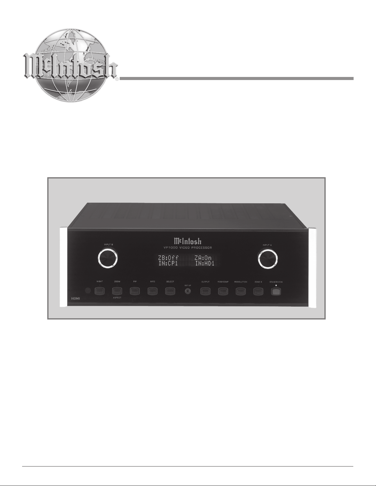
The McIntosh VP1000 Video Processor is one of the finest
video scalers, video signal enhancers and video switchers
ever created. The two zone video processor provides con-
nections for various video input sources and output formats
to monitors located in different rooms. The life like images
produced by the VP1000 are like being there in person.
ing in a viewing experience far superior to conventional
sharpness controls. This is accomplished by processing the
video signal in both the horizontal and vertical directions.
The results are smooth, vibrant, color-saturated images
that are truly film-like in quality.
• High Bandwidth Circuitry
The VP1000 is able to deliver the highest-quality video
images by utilizing ultra-linear components with an ex-
tremely wide bandwidth in excess of 300 MHz, which is
over three-times the bandwidth commonly used for HDTV
products. The Digital Video Internal Clock Exchange
circuitry regenerates the high frequency digital processing
clock from the incoming digital video signal thus provid-
ing superior performance when converting an incoming
1080i signal to 1080p scan output signal. This regeneration
maximizes the video performance for displaying signals
in true HDTV 1080p. There are seven individual settings
allowing adjustment of the digital processing clock phase
with respect to the video signal thus assuring the absolute
best picture quality.
• High Definition PIP Modes
The VP1000 is one of the first Video Processors to allow
two different video sources, both with High Definition
signals, to be viewed in either Picture-In Picture or Pic-
ture-By-Picture Modes.
• Automatic Synchronization Regeneration
The VP1000 automatically corrects for the unstable syn-
chronization signals that are part of an analog video signal
from sources such as VCR and Laser Disc players. The cir-
cuitry performing this correction is know as a Time Base
Corrector (TBC) and is normally only found in profes-
sional broadcast equipment. By first processing the analog
signal with the TBC, the best possible results are achieved
with the Digital Scaling and the other Video Enhancement
Circuitry.
• Enhanced HDMI Connectivity
The VP1000 HDMI (High-Definition Multimedia In-
terface) Circuitry goes beyond the typical HDMI imple-
mentation found in other products. Source components
connected to the VP1000 using the HDMI connections
are requested to provide the Highest Resolution Digital
Video and Audio Signals independent of the capability
of components connected to the VP1000 HDMI Outputs.
1 Using optional HDMI to DVI-D adapter available from your dealer

7
Introduction and VP1000 Features
The HDMI Output Circuitry analyzes any possible signal
delays caused by the interconnect cable and will automati-
cally compensate up to the maximum recommended cable
length.
• Information Displays
The Multifunction Front Panel Display indicates vari-
ous information including Source Selection and Output
Resolution. The Menu Options and Adjustments are also
displayed On-Screen including Aspect Ratio and various
video settings. The Front Panel Display intensity is also
adjustable.
• Precision Technology
The VP1000 uses the latest in design technology includ-
ing impedance matched multilayer surface mount circuitry
providing wideband, low-noise video processing.
• Remote Control and External Sensor Inputs
The Remote Control together with provisions to connect
external sensors, provides control of the VP1000 operating
functions.
• Total Component Integration
The VP1000 is designed to work seamless with the McIn-
tosh AP1000 Audio Processor and the McIntosh MDLP1
Digital Video Projector. It also integrates with the Mc-
Intosh MX Series A/V Control Centers including the
MX136, MX135, MX134, MX132, MX120 or MX119.
• Data Ports and RS232
There are Data Input Ports to allow communication be-
tween the VP1000 and other McIntosh components. An
RS232 Port also permits two way communication with
other components.
• Power Control Outputs
Power Control connections for convenient Turn-On of Mc-
Intosh Components and Accessories is included.
• Special Power Supply
Fully regulated Power Supplies ensure stable noise free
operation even though the power line varies.
• Extruded Side Panels
The sides of the VP1000 are extruded aluminum panels
with a bead blast textured surface and a black anodized
finish.
• Fiber Optic Solid State Front Panel Illumination
The even Illumination of the Front Panel is accomplished
by the combination of custom designed Fiber Optic Light
Diffusers and extra long life Light Emitting Diodes
(LEDs). The glass Front Panel ensures the pristine beauty
of the VP1000 will be retained for many years.

8
Dimensions
Dimensions
The following dimensions can assist in determining the
best location for your VP1000. There is additional informa-
tion on the next page pertaining to installing the VP1000
into cabinets.
17-1/2"
44.45cm
4-5/8"
11.75cm
6"
15.24cm
17"
43.18cm
18-3/8"
46.67cm
3/16"
0.48cm 4-13/16"
12.22cm
14"
35.56cm
1-3/8"
3.49cm
13 -1/4"
33.65cm
17-1/16"
43.34cm
5/8"
1.59cm
Front View of the VP1000
Rear View of the VP1000
Side View of the VP1000
5-3/8"
13.69cm
13/16"
2.06cm
120V
50/60Hz 50 WATTS

9
Installation
Installation
The VP1000 can be placed upright on a table or shelf,
standing on its four feet. It also can be custom installed in
a piece of furniture or cabinet of your choice. The four feet
may be removed from the bottom of the VP1000 when it is
custom installed as outlined below. The four feet together
with the mounting screws should be retained for possible
future use if the VP1000 is removed from the custom
installation and used free standing. The required panel
cutout, ventilation cutout and unit dimensions are shown.
Always provide adequate ventilation for your VP1000.
Cool operation ensures the longest possible operating life
for any electronic
instrument. Do
not install the
VP1000 directly
above a heat
generating com-
ponent such as
a high powered
amplifier. If all
the components
are installed in
a single cabinet,
a quiet running
ventilation fan
can be a definite
asset in maintain-
ing all the system
components at
the coolest pos-
sible operating
temperature.
A custom cabi-
net installation
should provide
the following
minimum spac-
ing dimensions
for cool opera-
tion.
Allow at least 2 inches (5.08cm) above the top, 2 inches
(5.08cm) below the bottom and 1 inch (2.54cm) on each
side of the Video Processor, so that airflow is not obstruct-
ed. Allow 19-1/2 inches (49.53cm) depth behind the front
panel. Allow 1-1/8 inch (2.9cm) in front of the mounting
panel for knob clearance. Be sure to cut out a ventilation
hole in the mounting shelf according to the dimensions in
the drawing.
4 -7/8"
12.38cm
17-1/16"
43.34cm
Cutout Opening for Custom Mounting
VP1000 Front Panel
Custom Cabinet Cutout
14"
35.56cm
14"
35.56cm
15-1/16"
38.26cm
17/32"
1.35cm
Cutout Opening
for Ventilation
Cutout Opening for Ventilation
Support
Shelf
Cabinet
Front
Panel
Chassis
Spacers
VP1000 Side View
in Custom Cabinet
VP1000 Bottom View
in Custom Cabinet
1"
2.54cm

10
Rear Panel Connections
The identification of Rear Panel Connections for the
VP1000 Video Processor is located on a separate folded
sheet contained in the Owner’s Manual Packet.
Refer to separate sheet “Mc1A” for the Rear Panel Connec-
tions
120V
50/60Hz 50 WATTS
VP1000 Video Processor Rear Panel

11
How to Connect the VP1000
The VP1000 has the ability to automatically switch power
On/Off to McIntosh Components via the Power Control
connections. The Data Port Connections allow for the
remote operation of the VP1000 from other McIntosh
Components. With an external sensor connected to the
VP1000, remote control operation is possible from another
room and/or when the VP1000 is located in a cabinet with
the doors closed.
The connection instructions below, together with the
AP1000/MDLP1/VP1000 Input and Control Connection
Diagrams located on the separate folded sheet “Mc2A and
B”, is an example of a typical audio/video system. Your
system may vary from this, however the actual components
would be connected in a similar manner.
For additional information refer to “Connector and
Cable Information” on page 6.
Note: With the addition of a McIntosh Power Control-
ler connected to the VP1000, any McIntosh Classic
Video Components and/or non McIntosh Video Com-
ponents connected to the VP1000 can be operated
more conveniently. Contact your McIntosh Dealer for
additional information.
Power Control Connections:
1. Connect a Control Cable from the VP1000 POWER
CONTROL OUT A Jack to the Power Control In Jack
on the McIntosh MDLP1 Video Projector.
If the VP1000 is connected to a McIntosh Audio/Video
Control Center MX136, MX135, MX134, MX132, MX120
or MX119 (MX Series) add the following connection:
2. Connect a Control Cable from the VP1000 POWER
CONTROL IN A Jack to the McIntosh MX Series
Power Control Zone A Out Jack.
Data Control Connections:
When the VP1000 is connected to the McIntosh AP1000
Audio Processor via the RS232 Data Port no addition Data
Port connections are necessary. If the VP1000 is connected
to a McIntosh MX Series Audio/Video Control Center
MX136, MX135, MX134, MX132, MX120 or MX119 add
the following connection:
3. Connect a Control Cable from the VP1000 DATA A
IN Jack to the McIntosh MX Series SUM A Data Port
Jack.
4. Optionally connect an adapter cable from the VP1000
DATA B IN Jack to the McIntosh MX Series Zone B
Keypad Connector. Refer to page 4 items 3, 4 and 5.
Video Connections:
When the VP1000 is connected to the McIntosh AP1000
Audio Processor add the following connections. If there is
no AP1000 proceed to step 8.
5. Connect a Video Cable from the VP1000 MATRIX
ZA OUT Jack to the McIntosh AP1000 Audio Proces-
sor ZA IN Jack.
6. Connect a Video Cable from the VP1000 MATRIX ZB
OUT Jack to the McIntosh AP1000 Audio Processor
ZB IN Jack.
7. Connect a Video Cable from the VP1000 COMPOS-
ITE 1 Jack to the McIntosh DVD Audio/Video Player
Video Out Jack.
8. Connect a Video Cable from the VP1000 COMPOS-
ITE 2 Jack to the McIntosh Music Server Video Out C
Jack.
9. Connect a Video Cable from the VP1000 COMPOS-
ITE INPUT 6 Jack to the McIntosh AP1000 Audio
Processor Video (EXT) Out Jack.
Note: When connecting to a McIntosh MX Series Audio/
Video Control Center use the MON A Composite
Output Jack.
10. Connect a Video Cable from the VP1000 S-VIDEO
INPUT 4 Jack to the VCR S-Video Out Jack.
11. Connect a Video Cable from the VP1000 MONitor A
S-VIDEO OUTPUT Jack to the VCR S-Video In Jack.
12. Connect Video Cables from the VP1000 COMPO-
NENT INPUT 2 Jacks to the Satellite Receiver Com-
ponent Video Output Jacks.
13. Connect Video Cables from the VP1000 COMPO-
NENT INPUT 3 Jacks to the TV Tuner Component
Video Output Jacks.
14. Connect Video Cables from the VP1000 COMPO-
NENT INPUT 4 Jacks to the McIntosh Music Server
Component Video Output Jacks.
15. Connect Video Cables from the VP1000 COMPO-
NENT INPUT 5 Jacks to the Digital Video Recorder
(DVR) Component Video Output Jacks.
16. Connect Video Cables from the VP1000 COMPO-
NENT MON B OUTPUT Jacks to the Digital Video
Recorder (DVR) Component Video Input Jacks.
17. Connect a HDMI Cable from the VP1000 HDMI IN-
PUT 1 Connector to the McIntosh DVD Audio/Video
Player HDMI Output Connector.
18. Connect a HDMI Cable from the VP1000 HDMI
MON A OUTPUT Connector to the McIntosh Video
Projector HDMI Input 1 Connector.
19. Connect a HDMI Cable from the VP1000 HDMI
AUXILIARY OUTPUT Connector to the McIntosh
AP1000 Audio Processor HDMI Input 1 Connector.
20. Connect any additional Video Components in a similar
manner, as outlined in steps 4 thru 13.
AC Power Cords Connections:
21. Connect the VP1000 AC Power Cord to a live AC out-
let and connect the remaining components’ AC Power
Cords.

12
Front Panel Indicators, Controls and Push-buttons
Standby Power
On Indicator
IR Sensor
receives
commands
from a
Remote
Control
STANDBY/ON
Push-button
switches the
VP1000 ON or
OFF (Standby)
and resets the
microprocessors
SETUP Mode Push-but-
ton activates the On-
Screen Menu, allowing
changes to various video
and other settings
DISPLAY indicates
the Zones, Sources
Operational Functions
and Menu Settings
Allows activation
and adjustments for
Zone B
Selects which of the
twenty-two Video
Sources available at
the Zone B Out-
put and up/down
directional navaga-
tion selection for the
On-Screen Menu
Allows selec-
tion of the video
output resolution
for the Compo-
nent and HDMI
Outputs
Allows selection
of the different
HD (High Defi-
nition) Digital
Output Color
Video Processing
Modes
Allows selec-
tion of different
options while
in the Setup
Mode and when
the On-Screen
menus are
activated during
normal opera-
tion
Activates an On-
Screen display indi-
cating the Input and
Output status of the
video signals
Activates the
Picture-In Picture
Display Mode
allowing the
simultaneously
viewing of two
different video
sources at the
same time
Allows selection of five
different Aspect Ratios
(screen height to width
sizes) and the preset
Zoom settings
Adjusts the
video signals
brightness and
contrast ratio
settings for im-
proved viewing
in a darkened
room
Indicates when
Zone B Control
is active
Indicates when
the Zoom Mode
is active
Indicates when
the Night Mode
is active
Selects which of the
twenty-two Video
Sources available at
the Zone A Out-
put and left/right
directional navaga-
tion selection for the
On-Screen Menu
Allows selection of
the different Analog
Output Color Video
Processing Modes

13
Front Panel Display
Display Indication Description
ZB:Off Zone B is Off
ZB:On Zone B Is On
ZA:Off Zone A is Off
ZA:On Zone A is On
ZB:On
IN:CP1
Zone B is On and the Input
selected is Component
Video 1
ZA:On
IN:HD1
Zone A is On and the Input
selected is HDMI 1
ZA OSD ACTIVE Zone A On-Screen Menu
is Active
ZB OSD ACTIVE Zone B On-Screen Menu
is Active
NIGHT:Off Preset Settings for Day
Time Viewing are active
NIGHT:On Preset Settings for Night
Time Viewing are active
ASPT:ANAM Picture Aspect Ratio is set
to Anamorphic Full Screen
ASPT:PANO Picture Aspect Ratio is set
to Panoramic Full Screen
ASPT:LETR Picture Aspect Ratio is set
to Letter/Pillar Box
ASPT:VSTR Picture Aspect Ratio is set
to V-Stretch
ASPT:ZOOM Picture Aspect Ratio is set
to Zoom
ASPT:THRU Picture Aspect Ratio is set
to Through
PIP:Off Picture in Picture Mode
is Off
PIP:P-IN-P Picture In Picture Display
Mode is active
PIP:P-BY-P Picture By Picture Display
Mode is active
Zone B Power
and
Input Selection
Zone A Power
and
Input Selection
Display Indication Description
HD:Auto The HD Video Output
Signal Color Signal format
is Automatic
HD:RGB The HD Digital Video
Output Signal Color Signal
format is RGB
HD:YCbCr The HD Digital Video
Output Signal Color Signal
format is YCbCr
ANA:YPbPr The Analog Video Output
Signal Color Signal format
is YPbPr
ANA:RGBHV The Analog Video Output
Signal Color Signal format
is RGB(with sync signals)
OUT:1920x1080p Video Output Resolution is
set to 1920x1080p
OUT:1920x1080i Video Output Resolution is
set to 1920x1080i
OUT:1920x540p Video Output Resolution is
set to 1920x540p
OUT:1360x768p Video Output Resolution is
set to 1360x768p
OUT:1280x768p Video Output Resolution is
set to 1280x768p
OUT:1280x720p Video Output Resolution is
set to 1280x720p
OUT:1024x768p Video Output Resolution is
set to 1024x768p
OUT:720x480p Video Output Resolution is
set to 720x480p
OUT:720x480i Video Output Resolution is
set to 720x480i

14
Remote Control Push-Buttons
Press to Power the
VP1000 ON or OFF
Activates the PIP Mode
Used together with the PROCcessor
INPUT Push-buttons to select Video
Inputs; also used for other numbered
operations
Allows selection from the available
video sources
Press to select and adjust various
functions
Selects which component, either the
VP1000 Processor or the McIntosh
MDLP Series Projector, the remote
control commands are sent to
Note: Push-buttons whose function is not identified above
are for use with the McIntosh Components
Press to Power ON or Power OFF
to the VP1000
LED illuminates during the time
a remote command is sent
Use to navigate up, down, to
the left and to the right through
the various menus. Also used
to select the desired function or
option
Selects Composite Video, S-Video,
Component Video or Digital Video
(HDMI) Inputs on the VP1000
Press to recall various
on-screen information
Press to change the out-
put Aspect Ratio of the
video image
Activates the various On-Screen
Menus
Press to select the preset settings
for daytime or nighttime viewing
Press to activate the Zoom Mode
Press to exit from the On-Screen
Menu

15
How to use the Remote Control
The supplied Remote Control is capable of directly control-
ling the functions of the McIntosh VP1000 Video Proces-
sor and the McIntosh MDLP Series Projector. For addition-
al information on the various video adjustments and their
purpose, please refer to the “How to Operate the VP1000”
section of this manual starting on page 20.
Input Source Selection
Press the PROCcessor INPUT Push-button followed by
pressing the Number Push-button corresponding to the
desired Input. Example, to select the Component Video
Input 2 first press the COMPonent Push-button followed
by pressing the NUMBER 2 Push-button.

16
The Default Settings Charts are for Zone A and Zone B.
For additional information on any given default setting
Default Settings
MENU SOURCE/FUNCTION ADJUSTMENT/SELECTION SETTING PAGE
Zones Zone A Default 25
Zone B - 25
Input Composite - 18
SVideo - 18
Component - 18
HDMI 1 18
Matrix(Composite) 1 18
Ouput PIP Off 23
Background Black 27
Aperture Horizontal Size 100 27
Vertical Size 100 27
Horizontal Position 050 27
Vertical Position 050 27
Resolution 1280x720P Default 24
Aspect Anamorphic Full Screen Default 21
Panoramic Full Screen - 21
Letter/Pillar Box - 21
V-Stretch - 22
Zoom Extract Size 100 28
Horizontal Position 050 28
Vertical Position 050 28
Through Horizontal Size 100 28
Vertical Size 100 28
Horizontal Position 050 28
Vertical Position 050 28
Video Image Contrast 050 25
Brightness 050 25
Detail Enhancement Detail Enhancement 000 28
Noise Threshold 000 28
Noise Reduction Noise Reduction 000 28
Motion Threshold Motion Threshold 004 28
HDMI Color Space HDMI Output Auto 29
HDMI Input Auto 29
Analog Output YPbPrDefault 29
refer to the page numbered in the far right column in the
chart.

17
Default Settings
MENU SOURCE/FUNCTION ADJUSTMENT/SELECTION SETTING PAGE
Assign Tuner Composite (1-6), SVideo (1-6), Component (1-6), or HDMI (1-4) - 18
Aux Composite (1-6), SVideo (1-6), Component (1-6), or HDMI (1-4) - 18
CD1 Composite (1-6), SVideo (1-6), Component (1-6), or HDMI (1-4) - 18
CD2 Composite (1-6), SVideo (1-6), Component (1-6), or HDMI (1-4) - 18
Tape 1 (REC 1) Composite (1-6), SVideo (1-6), Component (1-6), or HDMI (1-4) - 18
Tape 2 (REC 2) Composite (1-6), SVideo (1-6), Component (1-6), or HDMI (1-4) - 18
SAT (SAT 1) Composite (1-6), SVideo (1-6), Component (1-6), or HDMI (1-4) - 18
TV Composite (1-6), SVideo (1-6), Component (1-6), or HDMI (1-4) - 18
LV (SERV) Composite (1-6), SVideo (1-6), Component (1-6), or HDMI (1-4) - 18
VCR1 (DVR) Composite (1-6), SVideo (1-6), Component (1-6), or HDMI (1-4) - 18
VCR2 (SAT2) Composite (1-6), SVideo (1-6), Component (1-6), or HDMI (1-4) - 18
DVD Composite (1-6), SVideo (1-6), Component (1-6), or HDMI (1-4) - 18
Matrix
Tuner Composite (1-6) - 19
Aux Composite (1-6) - 19
CD1 Composite (1-6) - 19
CD2 Composite (1-6) - 19
Tape 1 (REC 1) Composite (1-6) - 19
Tape 2 (REC 2) Composite (1-6) - 19
SAT (SAT 1) Composite (1-6) - 19
TV Composite (1-6) - 19
LV (SERV) Composite (1-6) - 19
VCR1 (DVR) Composite (1-6) - 19
VCR2 (SAT2) Composite (1-6) - 19
DVD Composite (1-6) - 19
FRONT PANEL PUSH-BUTTON SELECTION SETTING PAGE
Output HD:Auto Default 21
HD:RGB - 21
HD:YCbCr- 21
RGB/COMP ANA:YPbPrDefault 21
ANA:RGBHV - 21
Resolution 1920x1080p - 20
1920x1080i - 20
1920x540p - 20
1400x1050p - 20
1360x768p - 20
1280x768p - 20
1280x720p Default 20
1024x768p - 20
720x480p - 20
720x480i - 20

18
3. Press the
►RIGHT
push-but-
ton us-
ing the
supplied
Remote
Control to
select the
ASSIGN
Icon. Refer to figures 4 and 12.
4. Using the
▼DOWN
Push-but-
ton select
DVD. Refer
to figure 5.
5. Press the
►RIGHT
push-but-
ton once
to select the type of video signal connection (HDMI,
Component, S-Video or Composite). Then, using the
►RIGHT and ▼DOWN push-buttons select COM-
PONENT 1 (the Input Number of the Rear Panel
Connector
the DVD
Player
Compo-
nent Video
Output is
connected
to). Refer
to figures 6
and 7.
Your McIntosh VP1000 Video Processor has default set-
tings allowing for immediate enjoyment of superb video
when connected to an HD TV/Monitor. The VP1000 is
designed to be used with the McIntosh AP1000 Audio Pro-
cessor. It also integrates with the McIntosh MX Series A/V
Control Centers including the MX136, MX135, MX134,
MX132, MX120 or MX119.
When the VP1000 is connected to the above Audio Pro-
cessor or one of the MX Series A/V Control Centers, both
components can function as if they were one component.
The VP1000 Input Selection, for both Zones A and B, will
track the selection made on the AP1000 Audio Processor.
It will also track the selection by using the Remote Control
supplied with the MX Series A/V Control Center. For this
unified functioning to occur, the Input(s) on the VP1000
must be assigned to match the desired Input(s) on the Au-
dio Processor or MX Series A/V Control Center. Perform
the following steps:
1. Press the STANDBY/ON Push-button to switch On the
VP1000. Refer to figure 1.
Note: The Red LED above the STANDBY/ON Push-button
lights to indicate the VP1000 is connected to a live
AC Outlet.
2. Press the VP1000 Front Panel SETUP Push-button.
The Front Panel Information Display will indicate ZA
OSD ACTIVE. Refer to figure 2. The On-Screen Menu
will also appear on the TV/Monitor. Refer to figure 3.
Note: If the Menu does not appear On-Screen, it may be
necessary to change the output resolution from the
default 1280x720p setting to the native resolution
of the TV/Monitor. Refer to page 20 for additional
information.
How to Setup the VP1000
Figure 2
Figure 1
ZB:Off ZA:On
ZA OSD ACTIVE
Figure 3
Figure 4
Figure 5

19
10. In a similar
manner,
assign any
additional
video
sources
connected
to the
VP1000.
11. Press the
MENU
Push-but-
ton on the
Remote
Control.
12. Verify the
VP1000
switches to
the cor-
rect Video
Input(s) when the matching
Input(s) on the McIntosh AP1000
is selected. Use the Remote Con-
trol supplied with the McIntosh
MX Series A/V Control Center to
verify VP1000 Source Selection.
13. Proceed to “How to Operate the
VP1000” on page 20.
6. Press the
SELECT
Push-but-
ton and a
check mark
will appear
to the left
of the title
name to
indicate the
selection is
entered into
memory.
Refer to
figure 8.
Note: If the VP1000 is not connected to the McIntosh
AP1000 or to an additional system TV/Monitor then
omit steps 7 thru 9.
7. Press the ◄LEFT push-button, then the ▼DOWN
Push-button to select MATRIX. Refer to figure 9.
8. Press the
►RIGHT
push-but-
ton to select
COMPOS-
ITE 1 (the
Input Num-
ber of the
Rear Panel
Connector
the DVD Player Composite Video Output is connected
to). Refer to figure 10.
9. Press the SELECT Push-button and a check mark
will appear to the left of the title name to indicate the
selection is entered into memory. Refer to figure 11.
Setup
Figure 12
Figure 6
Figure 7
Figure 8
Figure 9
Figure 10
Figure 11

20
the require-
ments of the
TV/Monitor
connected
to one of the
Zone A Moni-
tor Outputs by
performing the
following:
1. Press the
Front Panel RESOLUTION Push-button once. The
Front Panel Information Display will indicate the cur-
rent setting on the second line. Refer to figure 16.
2. By repeated pressing of the RESOLUTION Push-
button the VP1000 will step through in a continous
loop, all of the available resolution choices. When the
desired resolution appears on the display, stop pressing
the push-button. Within a few seconds the VP1000 will
switch to the new setting and the Front Panel Informa-
tion Display will return to the default display. Refer to
figures 17 and 18.
3. Press the SETUP Push-button or the MENU Push-but-
ton on the Remote Control to exit the Menu.
How to Operate the VP1000
Before operating the McIntosh VP1000 Video Processor it
is very important to perform Setup on pages 18 and 19, the
Input Assign Procedure. After assigment has been per-
formed the VP1000 together with the McIntosh AP1000,
will function as one component. The Assign Process will
also integrate the VP1000 with the McIntosh MX Series
A/V Control Centers including the MX136, MX135,
MX134, MX132, MX120 or MX119.
The VP1000 is a two Zone (A and B) Video Proces-
sor. Each Zone is operated independently including video
source selection, video processing of the selected source
and the switching of power (On and Off) to the respective
Zone (A and B). To Switch power On to Zone A perform
the following:
1. Press the STANDBY/ON Push-button on the Front
Panel to switch On the VP1000 or press the PWR
Push-button on the Remote Control. Refer to figures 13
and 22.
Note: The Red LED above the STANDBY/ON Push-button
lights to indicate the VP1000 is connected to a live
AC Outlet.
2. Press the VP1000 Front Panel SETUP Push-button.
The Front Panel Information Display will indicate ZA
OSD ACTIVE. The On-Screen Menu will also appear
on the TV/Monitor. Refer to figures 13, 14 and 15.
If the Menu does not appear On-Screen, it may be nec-
essary to change the output resolution from the default
1280x720p setting to the native resolution of the TV/Moni-
tor.
Resolution
The default output resolution may be changed to match
Figure 15
Figure 14
ZB:Off ZA:On
ZA OSD ACTIVE
Figure 16
ZB:Off ZA:On
OUT:1280x720p
Figure 17
ZB:Off ZA:On
OUT:1920x1080p
Figure 18
ZB:Off ZA:On
IN:CP1 IN:HD1
Figure 13
Other manuals for VP 1000
1
Table of contents
Other McIntosh Media Converter manuals

McIntosh
McIntosh VP 1000 User manual

McIntosh
McIntosh MAC-3 User manual

McIntosh
McIntosh MDA5000 User manual

McIntosh
McIntosh MDA1000 User manual

McIntosh
McIntosh MB50 User manual

McIntosh
McIntosh MDA700 User manual

McIntosh
McIntosh MDA1000 User manual

McIntosh
McIntosh MX122 User guide

McIntosh
McIntosh MDA200 User manual