page 3
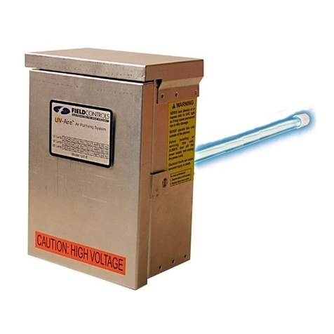
WARNING: Neverexpose eyesorskintoUVC lightfromanysource.Looking directlyattheUVClight maycausepermanenteyedamage
orblindness.NeveroperatetheUV-Aire™AirPurifyingSystemoutoftheplenum.Avoidtouchingtheglassportionofthelampwithyourhands.
INSTALLATION:
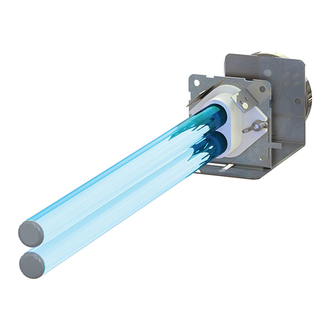
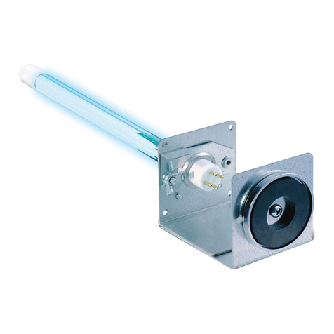
1. Choose a location for the Duo unit, with the following considerations:
a. The Duo unit will reduce organic buildup on an HVAC cooling/
heating coil by illumination with UVC germicidal rays. Locate
the Duo such that the maximum surface area of the coil is
illuminated, while installing as close to the coil as possible
without damage to the coil.
CAUTION: Use care to avoid damage to the coil and any wiring or other components while installing the
Duo 24V unit.
b. The Duo 24V unit must be installed with its power cable within reach of the included 24V
transformer, or the 24V power cable must be extended by using minimal 18 gauge wiring suitable for the
installation, with maximum extension length of 20 feet. DO NOT connect to the HVAC system
transformer, as this may overload the HVAC transformer and/or under-power the Duo 24V
unit, which may cause damage and will void the factory warranty. The included transformer is i
intended to be mounted on a 4x4 junction/conduit box or within an approved electrical enclosure. The
provided 24V transformer shall be connected to 115 or 230 VAC power.
c. The Duo 24V unit may be installed on either the supply or return plenum.
d. The Duo 24V unit may be installed in upow, downow, or horizontal ow ducts and plenums.
e. The Duo 24V unit may be installed directly onto a sheet metal air duct or plenum, or onto
berglass ductboard when installed using the included Ductboard Adapter Plate (see Figure 1).
2. Install the Duo 24V unit:
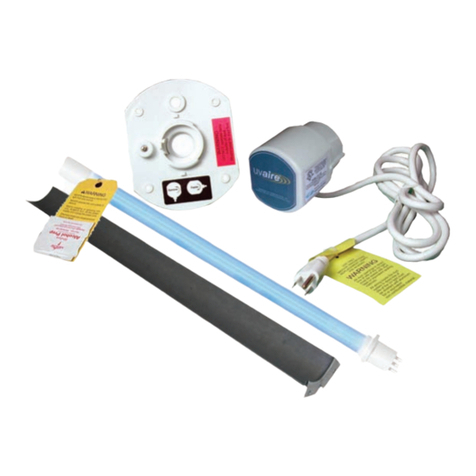
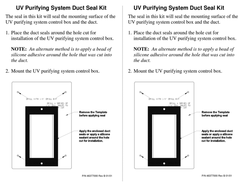
a. Hold or temporarily tape the included Ductboard Adapter Plate in the location chosen for
installation, and using the plate as a template, mark the mounting surface using the outermost
slots in the plate (see Figure 1). Alternatively, a 5-3/8” square may be marked on the mounting
surface.
b. Cut out the opening for the Duo unit in the mounting
surface, making sure to cut slightly outside the marked
lines if the Ductboard Adapter Plate was used as a template.
c. If mounting the Duo unit on ductboard: attach the Ductboard
Adapter Plate to the opening by folding the inner aps of the
plate into the opening and fully back against the inside of the
opening in the ductboard, either from the sides or from top
and bottom of the plate. Finish the Plate Adapter installation
by sealing around the edges of the plate to the ductboard,
using mastic foil tape or other material suitable for sealing
duct joints.
d. If the direction of airow in the duct is downward, the white
plastic ballast base that is attached to the Duo unit may
optionally be rotated 180 degrees from the position shown, so
the ballast label will not be upside down. If desired, remove the four screws attaching the base
to the Duo unit and re-install the base to the unit. Note: The white plastic base has a round sight
glass hole for observing the lamp inside the duct (the sight glass may be seen above the center
hole in the mounting base in Figure 2). There is a pair of holes in the Duo mounting ange that
allow the sight glass in the base to align with, in either position.glass may be seen above the
center hole in the mounting base in Figure 2). There is a pair of holes in the Duo mounting ange
that allow the sight glass in the base to align with it, in either position.
Figure 1
