FIELD TECH SCL800 Service manual
SCL800 Stairclimber Service & Installation
Bulletin
Assembly
The SCL 800 ships boxed and requires
assembly. Two technicians are recommended.
Assembly hardware is SAE and installation
requires the following tools:
•5/32” hex wrench
•7/32” hex wrench or socket
•1/2” wrench
Assembly guides ship with the unit. Care
should be taken when unboxing to gather all
parts and pieces prior to disposing of any
packaging. Assembly guides can be found on
each unit’s product page at Precor.com.
Once assembled, run the unit fully to check all
functions prior to putting into service
Console
The SCL 800 will only work with the P31
console.
Note: Some SCL 800 units were built with Version 1 of the P31 SCL 800 software
(305239-101 009). There is now a Version 2 that has minor updates, bug fixes and
has an updated build number from 009 to 012 (305239-101 012). If Version 1
software is found, use the CSAFE flashing procedure to update the console to Version
2.
To check the console software version on the console, access the information menu
and navigate to MAIN CONSOLE SW to view the current console software version. If
the build number is 009, flash the console using the 305239-101_bld012.a90
software file. P31 software can be found on the Precor Connect software page in the
General Release section under “Commercial UPCA SW (LED).”

Preventative Maintenance
Refer to the Cardio Maintenance Guide for SCL 800 preventative maintenance. All
basic maintenance and cleaning guidelines are applicable as well as the
following items specific to the SCL 800:
•Monthly
1. Note step count
2. Test Remote Motion Controls (RMC)
3. Clean and test obstruction sensor
•Quarterly
1. Inspect steps, step shafts, and bearings
2. Inspect primary drive chain tension
•Annually
1. Inspect sprockets
2. Inspect step chain and chain master link. Adjust chain tension as needed.
3. Clean step chain with soft brush and vacuum
Active Status Light
The Active Status Light works similarly to the ASL on the EFX 800. The
brightness can be adjusted and the ASL can be set to off if that is desired.
Located on the right lower corner of the unit, the ASL has the same color status
pattern as on other ASL equipped units. There are four supported states:
1. Solid blue- indicates normal operation
2. Pulsing blue - indicates preventative maintenance is required
3. Solid yellow - indicates an error has occurred but the machine is useable
4. Pulsing yellow - indicates a loss of major function was detected.
The Maintenance Counter will cause the ASL to flash blue after 1,100,000 steps.
The current maintenance step count can be found in the information
maintenance menus under MAINTENANCE COUNTER.

The counter starts at 1,100,000 steps and counts down. Press and hold the Start
button to reset. More information on the ASL’s functions and settings can be
found in the Active Status Light section of the service manual.
Covers
For access to most areas that will require maintenance and service, the covers
can be removed without tools (a small nylon tipped screwdriver or other slim
non-metallic tool may be needed to remove the gasket cover). Refer to the
maintenance manual for all cover removal/replacement procedures.
1) Gasket Cover
2) Top Cover
3) Forward Cover
4) Side covers
Speed Sensor
Both step speed and step count are monitored by the speed sensor system. The
SCL 800’s speed sensor system works with a cogged sprocket that passes in
front of two LEDs on the speed sensor board.
If the signals from the LEDs disagree by more than 20 steps per minute, or is
missing for more than 410 ms, the unit will generate an error.
Errors 13 and 70 are related to issues with the SCL800 speed sensor.
Care should be taken when working in this area as misalignment of the
sprocket could be one cause for speed sensor errors.
See the service manual for the speed sensor PCA board replacement and for sprocket
replacement.
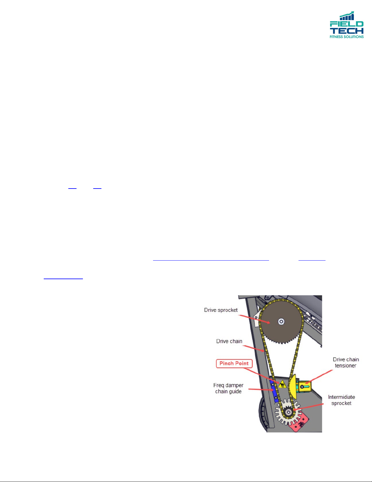
Drive Chain
Both the drive and step chain are made
from motorcycle 428 O-ring chain and
should require no maintenance outside
periodic cleaning.
The drive chain connects the speed sensor
drive sprocket to the step drive sprocket.
To remove the drive chain, the drive chain tensioner will be loosened which
will allow the chain to be removed.
Two distances will be measured to ensure proper tensioning. The gap between
the tensioner and tensioner guide will be 3/8” and the pinch point distance of
the chain between the tensionor and the damper chain guide should be greater
than 1” (2.5mm).
See the service manual for drive chain replacement and drive chain tensioning.
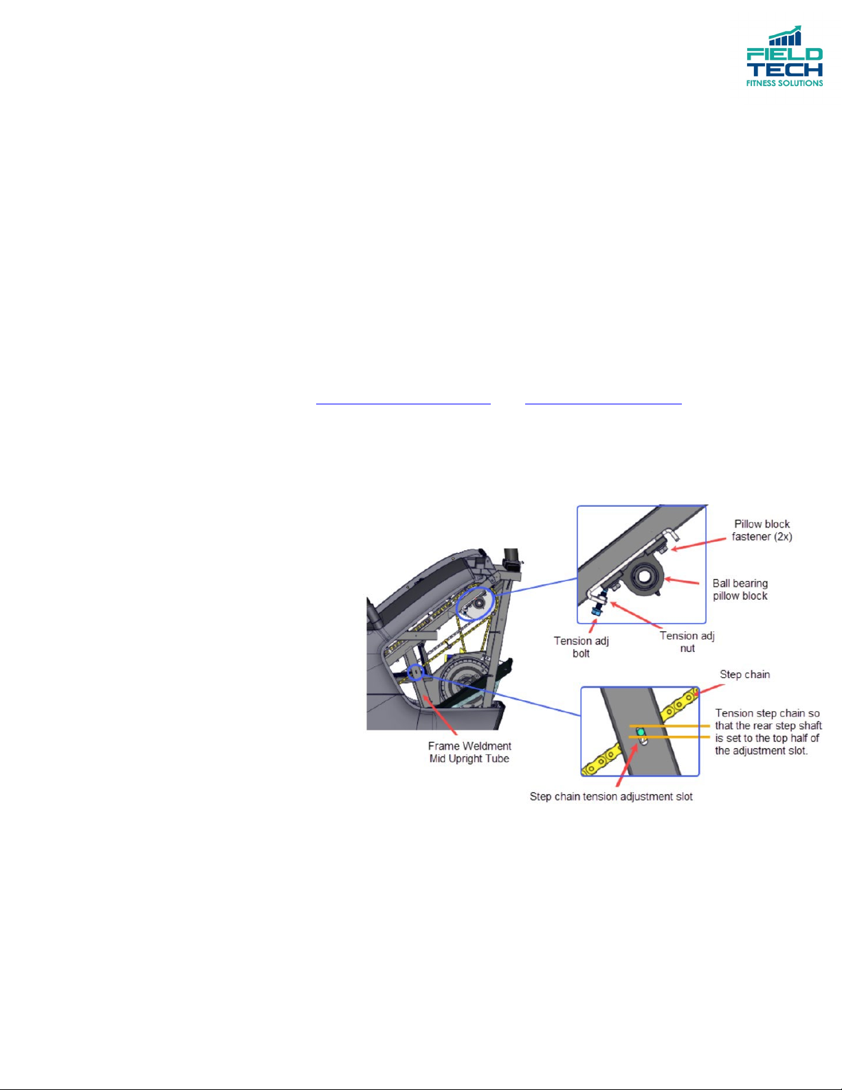
Step Chain
There are two step chains, one
on each side of the steps.
Tensioning is done at the
tensioning pillow blocks by
the top drive sprocket.
To check the step chain
tension, use the tension adjustment slot on the noted weldment. Tension
should be adjusted so that when looking through the adjustment slot, the end
of the step shaft is visible in the top half of the adjustment slot. Tensioning is
adjusted on both step chains.
Table of contents
Popular Fitness Equipment manuals by other brands


G-FITNESS
G-FITNESS AIR ROWER user manual

CAPITAL SPORTS
CAPITAL SPORTS Dominate Edition 10028796 manual

Martin System
Martin System TT4FK user guide

CIRCLE FITNESS
CIRCLE FITNESS E7 owner's manual

G-FITNESS
G-FITNESS TZ-6017 user manual

Accelerated Care Plus
Accelerated Care Plus OMNISTIM FX2 CYCLE/WALK user manual


