Field Tuff ATV-48ATVPS User manual
ATV Seeder
OWNER’S MANUAL
WARNING:
Read carefully and understand all ASSEMBLY AND OPERATION
INSTRUCTIONS before operating. Failure to follow the safety rules and other
basic safety precautions may result in serious personal injury.
20180601
Model # ATV-48ATVPS
Page of 15
2
Thank you very much for choosing this product! For future reference, please complete the
owner’s record below:
Model: Purchase Date: _______________
Save the receipt, warranty and these instructions. It is important that you read the entire manual
to become familiar with this product before you begin using it.
This product is designed for certain applications only. The manufacturer cannot be responsible
for issues arising from modification. We strongly recommend this product not be modified and/or
used for any application other than that for which it was designed. If you have any questions
relative to a particular application, DO NOT use the product until you have first contacted us to
determine if it can or should be performed on the product.
INTENDED USE
This ATV seeder has 8 rows to seed corn, beans, oats, etc. There are two boxes with closeable
slides for each row. The seeder has adjustable slots to use for different types of seed. This
seeder is also able to seed grain.
TECHNICAL SPECIFICATIONS
Weight
529 lbs
Rated Horse Power
Minimum 20 HP
Seeding Rows
8
Row Spacing
5.3 inches
Seed Rate
Each hole up to 20 lbs per acre
GENERAL SAFETY RULES
WARNING: Read and understand all instructions. Failure to follow all instructions listed
below may result in serious injury.
CAUTION: Do not allow persons to operate or assemble this seeder until they have
read this manual and have developed a thorough understanding of how the seeder works.
WARNING: The warnings, cautions, and instructions discussed in this instruction
manual cannot cover all possible conditions or situations that could occur. It must be
understood by the operator that common sense and caution are factors which cannot be built into
this product, but must be supplied by the operator.

Page of 15
3
SAVE THESE INSTRUCTIONS
WORK AREA
•Keep work area clean, free of clutter and well lit. Cluttered and dark work areas can cause
accidents.
•Keep children and bystanders away while operating a seeder. Distractions can cause you to
lose control, so visitors should remain at a safe distance from the work area.
•Be alert of your surroundings. Using a seeder in confined work areas may put you
dangerously close to cutting tools and rotating parts.
PERSONAL SAFETY
•Stay alert, watch what you are doing and use common sense when using a seeder. Do not use
a seeder while you are tired or under the influence of drugs, alcohol or medication. Amoment of
inattention while operating a seeder may result in serious personal injury.
•Dress properly. Do not wear loose clothing, dangling objects, or jewelry. Keep your hair,
clothing and gloves away from moving parts. Loose clothes, jewelry or long hair can be caught
in moving parts.
•Use safety apparel and equipment. Use safety goggles or safety glasses with side shields
which comply with current national standards, or when needed, a face shield. Use a dust mask if
working in dusty work conditions. This applies to all persons in the work area.Also use non-skid
safety shoes, hardhat, gloves, dust collection systems, and hearing protection when
appropriate.
SEEDER USE AND CARE
•Do not modify the seeder in any way. Unauthorized modification may impair the function
and/or safety and could affect the life of the equipment. There are specific applications for which
the seeder was designed.
•Always check for damaged or worn out parts before using the seeder. Broken parts will
affect the seeder operation. Replace or repair damaged or worn parts immediately.
•Do not exceed the seeder load capacity.
•Distribute the load evenly. Uneven loads may cause the seeder to tip, resulting in personal
injury to the operator or others.
•Use the seeder on flat and level surfaces capable of supporting the seeder and its maximum
load. Pulling or pushing a load on a slanted or uneven surface can result in loss of control.
•Store idle seeder. When seeder is not in use, store it in a secure place indoors and out of the
reach of children. Inspect it for good working condition prior to storage and before re-use.
INTENDED USE
1. Suitable for drilling corn, beans, oats, small grains, etc. in level or gently rolling fields.
2. The double disc coulters create an opening to seed easily in tilled soil.
3. The depth of seeding can be adjusted. Seeding quantity can be adjusted.
4. The seeder can plant seeds, roll, and drag all at the same time.

Page of 15
4
SAFETY PRECAUTIONS AND OPERATION RULES
1. Note the following in order to avoid fertilizer burn:
a. The seed rate should be controlled according to your field condition.
2. Always inspect, maintain or adjust the seeder after each use.
3. While operating the seeder, keep area clean, free of clutter and well lit. Keep children and
bystanders away. Distractions can cause you to lose control, so bystanders should remain at a
safe distance from the work area.
4. The seeder should raise and lower smoothly.
5. The seeder should be inspected prior to each use. Carefully check all bolts, nuts, chains
sprockets etc. to make sure they are in good condition and properly tightened. Keep guards in
place at ALL times.
6. Keep the hopper clean and make sure there is no moisture inside before you fill with seed and
fertilizer.
7. Working speed can be 3 -5 miles/hr.
8. DO NOT stand/sit between the seeder and the tractor/ATV/UTV while operating.
9. DO NOT go in reverse or turn sharply while seeder is in the ground.
10. During planting, avoid unnecessary stopping in the field to maintain consistent seed spacing.
11. Driver should have experience and be familiar with using this type of equipment.
12. The tractor/ATV/UTV should be stopped when adding seed and performing maintenance.
13. DO NOT go under the seeder for inspecting or repairing while seeder is in the up position.
Page of 15
5
ASSEMBLY
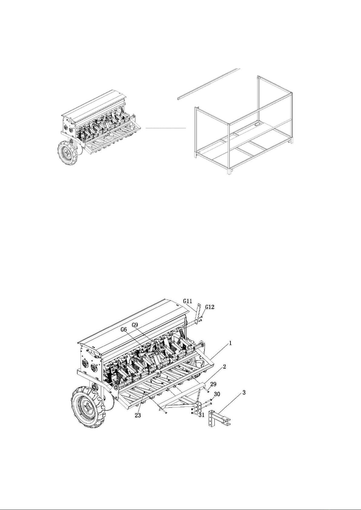
Step #1:
Remove the seeder from the crate.
Step #2:
Connect the Support seat (#2) to the Seeder Rack (#1), using four Hex Bolts M10*60(#29) and four
Hex Lock Nuts M10 (#23);
Step #3:
Connect the Connecting base (#3) to the Support seat (#2),using two Hex Bolts M12*80(#30) and
two Hex Lock Nuts M12 (#31);
Step #4:
Connect the Handle component (#G11) to the Control handle component (#G9), using two Hex
Bolts M10*25(G12) and two Hex Lock Nuts M10 (G6);

Page of 15
6
Step #5:
Connect the Connecting base (#3) to theATV;
Step #6:
Pull the Handle component (#G11), to raise the seeder coulters (#12) off the ground, then drive ATV
to the destination.
Step #7:
Connect the Drag Mat (#46) to the Seeder Rack (#1).
Page of 15
7
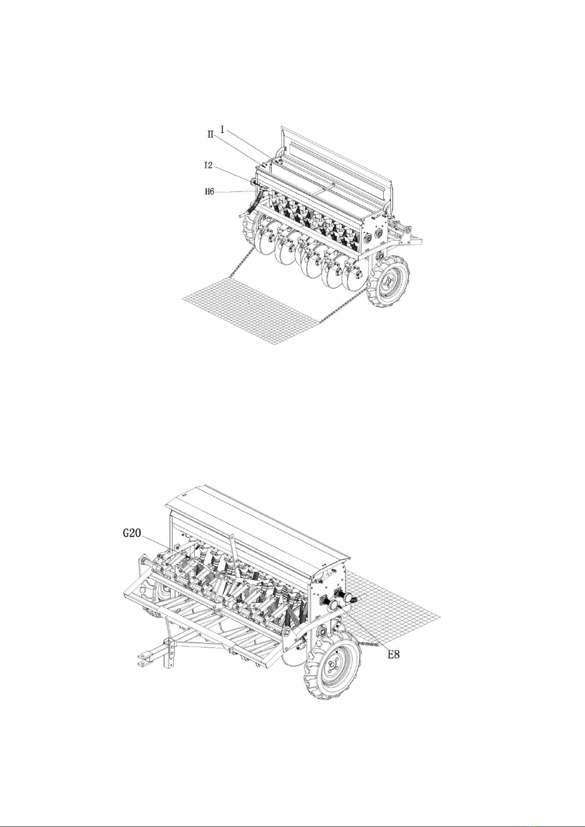
Step #8:
Open the material box ‘s cover plate, Close the two hose plate covers (#I2), then Close the front
eight plate covers (#H6), put the fertilizer into Hopper I, and close other eight plate covers (#H6), put
the seed into Hopper II. Close the material box.
Step #9:
Turn the Control hand wheel (#E8) to adjust the seed rate, turn clockwise to reduce the rate,
counter clockwise to increase the rate.
Step #10:
Turn the Transmission rod (#G20) to adjust the seed/fertilizer depth, turn clockwise for shallow
depths and counter clockwise for deeper depths.

Page of 15
8
Step #11:
Open the sixteen plate covers (#H6) to prepare to seed.
Step #12:
Drive the ATV, Pull the Handle component (#G11) to lower the seeder coulters (#12) into the ground.
Then begin to seed.
Step #13:
Close the sixteen plate covers (#H6), and open the two hose plate covers (#I2), to clear the seed
and fertilizer.
Step #14:
Take off the Drag Mat (#46), and pull the Handle component (#G11) to raise the coulter (#12) off the
ground, then pull ahead.

Page of 15
9
PART DIAGRAMS

Page of 15
10
Part List
Part #
Description
QTY
Part #
Description
QTY
1
Seeder Rack
1
29
Hex bolt M10*60
10
2
Support seat
1
30
Hex bolt M12*80
2
3
Connecting base
1
31
Hex Lock Nut M12
2
4
Hopper
1
32
Guiding pad
8
5
Adjustment for seeding
2
33
Block piece
8
6
Seeding component
16
34
Spring
8
7
Discharge component
2
35
Rod A for spring
4
8
Clutch component
1
36
Rod B for spring
4
9
Intermittent Component
1
37
Cotter Ø5*25
8
10
Right wheel component
1
38
U Bolt
8
11
Left wheel component
1
39
Adjusting plate A
8
12
Coulter
8
40
Adjusting plate B
8
13
Hexagon bearing
2
41
Hex bolt M8*35
8
14
Shaft ring Ø30
2
42
Hex bolt M10*40
8
15
Hex bolt M8*20
20
43
Hex bolt M10*25
8
16
Bearing housing
4
44
Hex bolt M10*65
6
17
Deep groove ball bearing
4
45
Fixed plate for
square shaft
2
18
Hexagonal shaft sprocket
part
2
46
Drag Mat
1
19
Hex Lock Nut M8
30
47
Pull plate
1
20
Circular shaft
1
48
Tension spring for handle
1
21
Circular shaft sprocket part
1
49
Tensioning wheel
2
22
Hexagon socket head cap
screw
1
50
Tensioning wheel bushing
2
23
Hex Lock Nut M10
38
51
ChainA
1
24
Square shaft sheath
2
52
Chain B
1
25
Hex bolt M10*30
6
53
Intermittent Transmission
components
1
26
Hex bolt M8*55
2
54
Lift arm
2
27
Screw support plate
1
55
Clutch lift component
1
28
Fixed plate
1
Left Wheel Component Diagram
Part #
Description
QTY
A1
Hex bolt M14*25
4
A2
Tire
1
A3
Hex Lock Nut M14
4
A4
Fixed base A for tire
1
A5
Hex bolt M10*55
3
A6
Bearing housing
2
A7
Deep groove ball bearing
2
A8
Shaft ring Ø35
2
A9
Hex Lock Nut M10
3

Page of 15
11
Right Wheel Component Diagram
Part #
Description
QTY
B1
Hex bolt M14*25
4
B2
Tire
1
B3
Fixed base B for tire
1
B4
Hex Lock Nut M14
4
B5
Hex bolt M10*55
3
B6
Bearing housing
2
B7
Deep groove ball bearing
2
B8
Shaft ring Ø35
2
B9
Hex Lock Nut M10
3
B10
Hex Lock Nut M8
1
B11
Chain wheel
1
B12
Hexagon socket head cap
screw
1
Coulter Diagram
Part #
Description
QTY
C1
Hex Lock Nut M6
8
C2
Dust cap
2
C3
Nut
4
C4
External hexagon nut
1
C5
Bearing housing
2
C6
Deep groove ball bearing
2
C7
Disc
2
C8
Sealing washer
2
C9
Hex bolt M6*16
8
C10
Coulter welding part
1
C11
Thin hexagon nut
1
C12
Outside scraping clay
plate
1
C13
Hex bolt M6*12
1
C14
Inside scraping clay plate
1
C15
Fixed base for the Inside
scraping clay plate
1

Page of 15
12
Clutch Component Diagram
Part #
Description
QTY
D1
Cotter Ø5*45
2
D2
Flat
2
D3
Chain wheel
1
D4
Round pin Ø10*30
1
D5
Master spoon
1
D6
Flat key
1
D7
Subordinate spoon
1
D8
Clutch
1
D9
Spring
1
D10
Cotter Ø2*16
2
D11
Threaded rod
1
D12
Hex Lock Nut M10
2
D13
Connecting Part
1
D14
Oil zerk
1
Adjustment For Seeding Diagram
Part #
Description
QTY
E1
Flat Ø16
2
E2
Cotter Ø4*35
2
E3
Hex Lock Nut M8
4
E4
Nut retainer
1
E5
Hex bolt M8*20
4
E6
Check ring
1
E7
Locknut
1
E8
Control hand wheel
1
E9
Handwheel cover
1
Page of 15
13
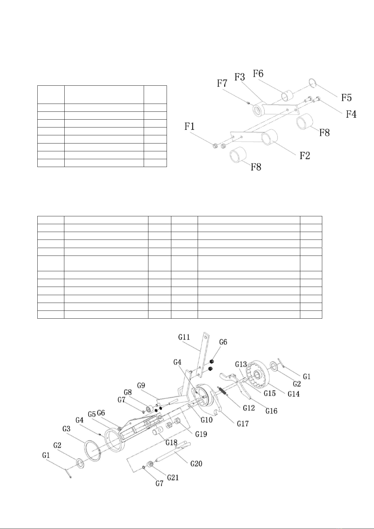
Pull Plate Diagram
Part #
Description
QTY
F1
Hex Lock Nut M10
2
F2
Sleeve A
1
F3
Sleeve B
1
F4
Hex bolt M10*25
2
F5
Steel Cable Baffle Ring
1
F6
Bush
1
F7
Oil zerk
1
F8
Pipe
2
Intermittent Components Diagram
Part #
Description
QTY
Part #
Description
QTY
G1
Cotter Ø5*45
2
G12
Tension spring
1
G2
Flat
2
G13
Cotter Ø2*16
1
G3
Shaft ring Ø110
1
G14
Intermittent driving components
1
G4
Oil zerk
2
G15
Flat key
1
G5
Intermittent transmission
component
1
G16
Hook
1
G6
Hex Lock Nut M10
2
G17
Eccentric component
1
G7
Shaft ring Ø12
1
G18
Round pin of transmission rod
1
G8
Wheel
1
G19
Hex Nut M18
2
G9
Control Handle
1
G20
Transmission rod
1
G10
Round pin Ø12*30
1
G21
Transmission rod base
1
G11
Handle component
1
Page of 15
14
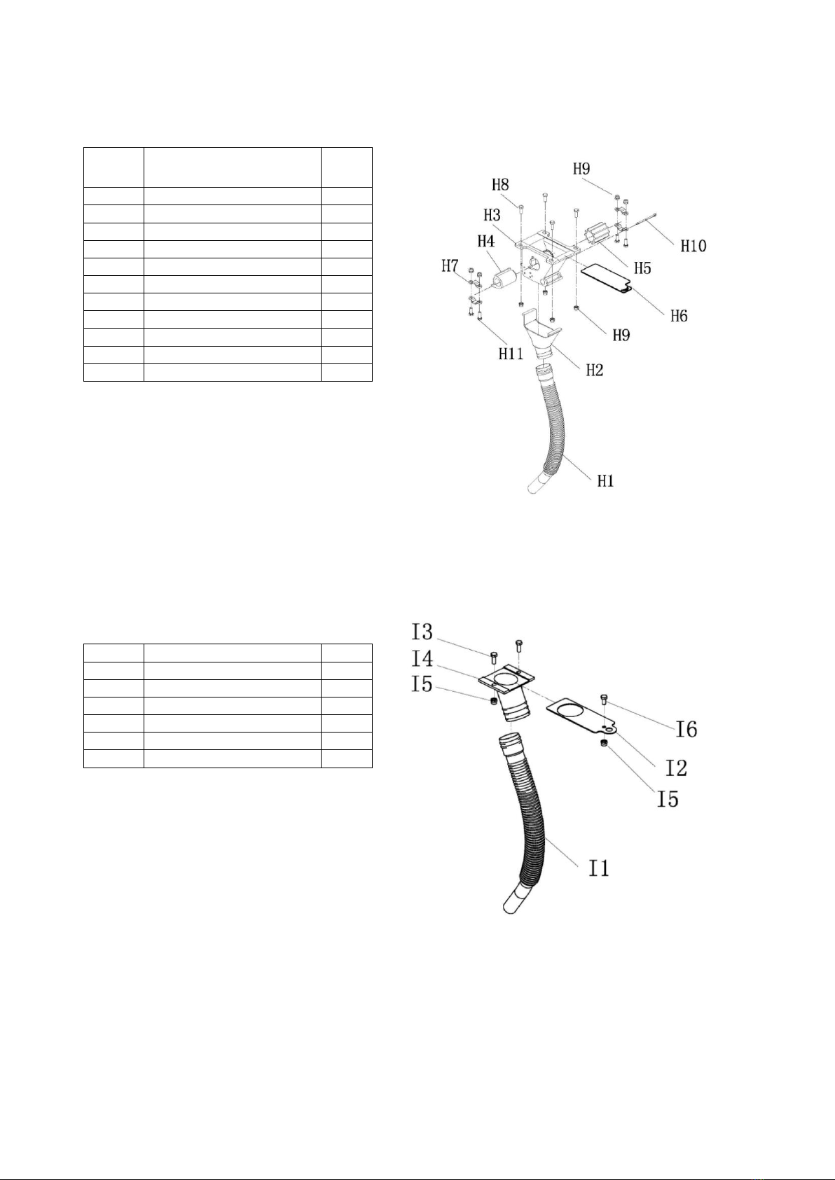
Seeding Component Diagram
Part #
Description
QTY
H1
Seeding pipe
1
H2
Seeding funnel
1
H3
Seeding component
1
H4
Blocking part
1
H5
Seeding wheel
1
H6
Plate Cover
1
H7
Hexagonal axis bolt
4
H8
Hex bolt M6*16
4
H9
Hex Lock Nut M6
8
H10
Cotter Ø3*55
1
H11
Hex bolt M6*20
4
Discharge component Diagram
Part #
Description
QTY
I1
Hose
1
I2
Hose Plate Covers
1
I3
Hex bolt M6*16
2
I4
Hose opening
1
I5
Hex Lock Nut M6
2
I6
Hex bolt M6*12
1

Page of 15
15
Hopper Diagram
For technical questions, Please call 218-943-6296
WARRANTY
One-year limited parts warranty.
TG
PO BOX 203
Miltona, MN 56354
MADE IN CHINA
Part #
Description
QTY
Part #
Description
QTY
J1
Left side plate
1
J9
Left plate
1
J2
Right side plate
1
J10
Right plate
1
J3
Clapboard
1
J11
Hex bolt M8*25
4
J4
Hopper body
1
J12
Hex bolt M8*35
2
J5
Hopper Cover
1
J13
Hex nut M8
10
J6
Hex bolt M6*12
28
J14
Hex Lock Nut M8
6
J7
Hex Lock Nut M6
28
J15
Flat washer Ø8
6
J8
Gas spring
2
Table of contents
Other Field Tuff Seeder manuals

Popular Seeder manuals by other brands


John Shearer
John Shearer 6M Airdrill Operator's manual

Gaspardo
Gaspardo CHRONO 300 Use and maintenance

Prodana Seeds
Prodana Seeds Proseeder HP600 operating instructions

Finn
Finn HydroSeeder T30 Operator Instructions And Parts Manual

Earth Way
Earth Way 1001-B Assembly instructions

GREAT PLAINS
GREAT PLAINS CTA4000HD Operator's manual

