Landoll Brillion SSP4 User manual


i
Table of Contents
1 Safety Information
Introduction . . . . . . . . . . . . . . . . . . . . . . . . . . . . . . . . . . . . . . . . . . . . . . . . . . . . . . . . . . . . . . . . . . 1-1
Description of Unit . . . . . . . . . . . . . . . . . . . . . . . . . . . . . . . . . . . . . . . . . . . . . . . . . . . . . . . . . . . . . 1-1
Using this Manual . . . . . . . . . . . . . . . . . . . . . . . . . . . . . . . . . . . . . . . . . . . . . . . . . . . . . . . . . . . . . 1-1
Owner Assistance . . . . . . . . . . . . . . . . . . . . . . . . . . . . . . . . . . . . . . . . . . . . . . . . . . . . . . . . . . . . . 1-1
Warranty Registration . . . . . . . . . . . . . . . . . . . . . . . . . . . . . . . . . . . . . . . . . . . . . . . . . . . . . . . . . . 1-1
Understanding Safety Statements . . . . . . . . . . . . . . . . . . . . . . . . . . . . . . . . . . . . . . . . . . . . . . . . 1-2
Keep Riders Off of Machinery . . . . . . . . . . . . . . . . . . . . . . . . . . . . . . . . . . . . . . . . . . . . . . . . . . . . 1-2
Transporting Safety . . . . . . . . . . . . . . . . . . . . . . . . . . . . . . . . . . . . . . . . . . . . . . . . . . . . . . . . . . . . 1-2
Safety Instructions for Towing Vehicles . . . . . . . . . . . . . . . . . . . . . . . . . . . . . . . . . . . . . . . . 1-3
Attaching, Detaching and Storage . . . . . . . . . . . . . . . . . . . . . . . . . . . . . . . . . . . . . . . . . . . . . . . . 1-3
Maintenance Safety . . . . . . . . . . . . . . . . . . . . . . . . . . . . . . . . . . . . . . . . . . . . . . . . . . . . . . . . . . . . 1-3
High Pressure Fluid Safety . . . . . . . . . . . . . . . . . . . . . . . . . . . . . . . . . . . . . . . . . . . . . . . . . . . . . . 1-3
Protective Equipment . . . . . . . . . . . . . . . . . . . . . . . . . . . . . . . . . . . . . . . . . . . . . . . . . . . . . . . . . . 1-3
Chemical Safety . . . . . . . . . . . . . . . . . . . . . . . . . . . . . . . . . . . . . . . . . . . . . . . . . . . . . . . . . . . . . . . 1-3
Prepare for Emergencies . . . . . . . . . . . . . . . . . . . . . . . . . . . . . . . . . . . . . . . . . . . . . . . . . . . . . . . . 1-3
2 Assembly of Optional Equipment
Agitator Blades (Optional Cage or Brushes) . . . . . . . . . . . . . . . . . . . . . . . . . . . . . . . . . . . . . . . . 2-1
Changing Agitator Kits . . . . . . . . . . . . . . . . . . . . . . . . . . . . . . . . . . . . . . . . . . . . . . . . . . . . . . . . . 2-1
Lift Sling Kit (Optional) . . . . . . . . . . . . . . . . . . . . . . . . . . . . . . . . . . . . . . . . . . . . . . . . . . . . . . . . . 2-2
Acre Meter (Optional) . . . . . . . . . . . . . . . . . . . . . . . . . . . . . . . . . . . . . . . . . . . . . . . . . . . . . . . . . . . 2-4
3 Operation
Seeder Operation . . . . . . . . . . . . . . . . . . . . . . . . . . . . . . . . . . . . . . . . . . . . . . . . . . . . . . . . . . . . . . 3-1
Parking Pin . . . . . . . . . . . . . . . . . . . . . . . . . . . . . . . . . . . . . . . . . . . . . . . . . . . . . . . . . . . . . . 3-1
Seed Rate Adjustment- Front Box . . . . . . . . . . . . . . . . . . . . . . . . . . . . . . . . . . . . . . . . . . . . . . . . 3-2
Pointer Adjustment . . . . . . . . . . . . . . . . . . . . . . . . . . . . . . . . . . . . . . . . . . . . . . . . . . . . . . . . 3-2
Seed Rate Adjustment - Rear Agitator Box . . . . . . . . . . . . . . . . . . . . . . . . . . . . . . . . . . . . . . . . . 3-3
Seed Rate Calibration . . . . . . . . . . . . . . . . . . . . . . . . . . . . . . . . . . . . . . . . . . . . . . . . . . . . . . . . . . 3-4
Chain Tension . . . . . . . . . . . . . . . . . . . . . . . . . . . . . . . . . . . . . . . . . . . . . . . . . . . . . . . . . . . . . . . . 3-7
Adjustment of the Wheel Track Remover . . . . . . . . . . . . . . . . . . . . . . . . . . . . . . . . . . . . . . . . . . 3-8

ii
Roller Wheels . . . . . . . . . . . . . . . . . . . . . . . . . . . . . . . . . . . . . . . . . . . . . . . . . . . . . . . . . . . . . . . . . 3-8
Settings for Loup Acre Meters After 05/15/2012 . . . . . . . . . . . . . . . . . . . . . . . . . . . . . . . . . . . . . 3-9
Field Acres . . . . . . . . . . . . . . . . . . . . . . . . . . . . . . . . . . . . . . . . . . . . . . . . . . . . . . . . . . . . . . . 3-9
Total Acres . . . . . . . . . . . . . . . . . . . . . . . . . . . . . . . . . . . . . . . . . . . . . . . . . . . . . . . . . . . . . . . 3-9
Pulses Per 400 Feet . . . . . . . . . . . . . . . . . . . . . . . . . . . . . . . . . . . . . . . . . . . . . . . . . . . . . . . 3-9
Width . . . . . . . . . . . . . . . . . . . . . . . . . . . . . . . . . . . . . . . . . . . . . . . . . . . . . . . . . . . . . . . . . . . 3-9
Password . . . . . . . . . . . . . . . . . . . . . . . . . . . . . . . . . . . . . . . . . . . . . . . . . . . . . . . . . . . . . . . . 3-9
Changing The Password . . . . . . . . . . . . . . . . . . . . . . . . . . . . . . . . . . . . . . . . . . . . . . . . . . . 3-10
Quick-start Settings for Loup Acre Meters Prior to 05/15/2012 . . . . . . . . . . . . . . . . . . . . . . . . 3-10
To Program Meter . . . . . . . . . . . . . . . . . . . . . . . . . . . . . . . . . . . . . . . . . . . . . . . . . . . . . . . . 3-10
To Enter Password . . . . . . . . . . . . . . . . . . . . . . . . . . . . . . . . . . . . . . . . . . . . . . . . . . . . . . . 3-10
To Disable Password . . . . . . . . . . . . . . . . . . . . . . . . . . . . . . . . . . . . . . . . . . . . . . . . . . . . . . 3-10
Battery Replacement . . . . . . . . . . . . . . . . . . . . . . . . . . . . . . . . . . . . . . . . . . . . . . . . . . . . . . 3-10
4 Maintenance & Specifications
General Torque Specifications . . . . . . . . . . . . . . . . . . . . . . . . . . . . . . . . . . . . . . . . . . . . . . . . . . . 4-1
Hydraulic Fitting Torque Specifications . . . . . . . . . . . . . . . . . . . . . . . . . . . . . . . . . . . . . . . . . 4-2
Acre Meter . . . . . . . . . . . . . . . . . . . . . . . . . . . . . . . . . . . . . . . . . . . . . . . . . . . . . . . . . . . . . . . . . . . . 4-3
Fasteners . . . . . . . . . . . . . . . . . . . . . . . . . . . . . . . . . . . . . . . . . . . . . . . . . . . . . . . . . . . . . . . . . . . . . 4-3
Lubrication . . . . . . . . . . . . . . . . . . . . . . . . . . . . . . . . . . . . . . . . . . . . . . . . . . . . . . . . . . . . . . . . . . . 4-3
Reference Tables and Specifications . . . . . . . . . . . . . . . . . . . . . . . . . . . . . . . . . . . . . . . . . . . . . . 4-4

1-1
Chapter 1
Safety Information
Introduction
The implement described in this manual has been
designed with care and built by skilled workers using
quality materials and processes. Proper assembly,
maintenance and safe operation will allow this implement
to provide you with satisfactory use for seasons to come.
DANGER
Description of Unit
The Brillion SS Series Seeder combines the features of
our popular and reliable Sure Stand Seeder with
additional box capacity.
Using this Manual
This manual will familiarize you with safety, assembly,
operation, adjustment and maintenance. Read this
manual and follow the recommendations to help ensure
safe and efficient operation.
• The information in this manual is current at the time of
printing. Some parts may change to assure peak
performance.
• Location reference: Right and Left designations in this
manual are determined by facing the direction the
implement will travel during field operation, unless
otherwise stated.
Owner Assistance
If customer service or repairs are needed, contact your
Brillion dealer. Your implement’s parts should only be
replaced with Brillion parts. Have the Serial Number and
complete Model Number available when ordering parts
from your Brillion dealer. If items covered in this manual
are not understood, contact your local Brillion Dealer.
Warranty Registration
Brillion Farm Equipment, by Landoll, shall have no
warranty obligation unless each product is registered,
within 10 days of retail purchase, using the Landoll
Corporation Ag Products on-line registration process.
Please refer to the Ag Products Policy and Procedures
Manual, accessible at www.landoll.com for step by step
instructions regarding product registration.
Enter your product information below for quick reference.
MODEL NUMBER
SERIAL NUMBER
DATE OF PURCHASE
Refer to the ID plate as shown in Figure 1-1. The ID plate
is located on the right front of the machine.
Figure 1-1: ID Plate
Read this entire manual before attempting to
assemble, adjust or operate this implement.
Failure to comply with this warning can result in
personal injury or death, damage to the
implement or its components and inferior
operation.
MODEL #
SERIAL #
MADE IN USA 1-573-010006
Landoll Company, LLC
Marysville, Kansas
www.landoll.com

1-2 7K555
SAFETY INFORMATION
Federal law requires that you explain the safety and
operating instructions furnished with this implement to all
operators before they are allowed to operate the
implement. These instructions must be repeated to the
operators at the beginning of each season. Be sure to
observe and follow the instructions for the safety of
anyone operating or near the implement.
NOTE
Investigation has shown that nearly 1/3 of all farm
accidents are caused by careless use of machinery.
Insist that all people working with you or for you abide by
all safety instructions.
Understanding Safety
Statements
You will find various types of safety information on the
following pages and on the implement decals (signs)
attached to the vehicle. This section explains their
meaning.
NOTICE
CAUTION
WARNING
DANGER
NOTE
You should read and understand the information
contained in this manual and on the implement decals
before you attempt to operate or maintain this equipment.
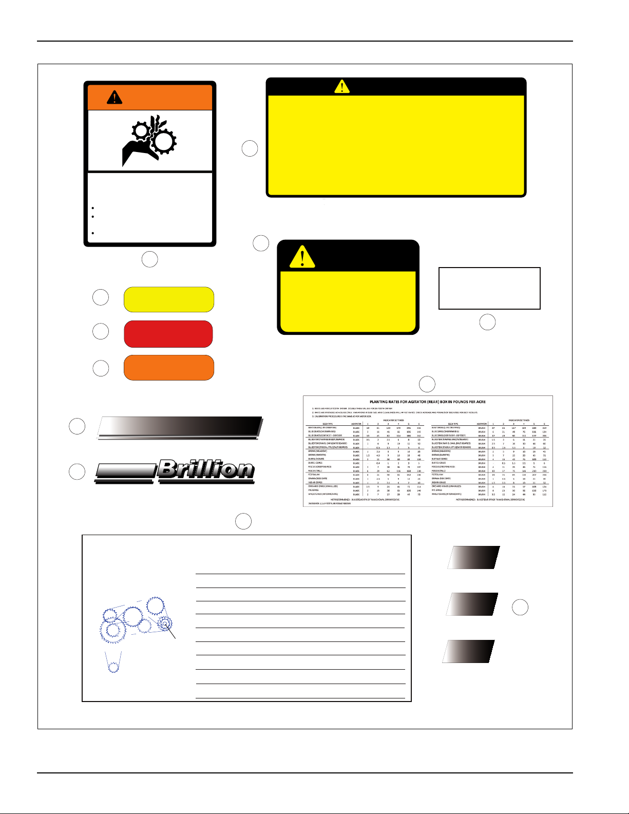
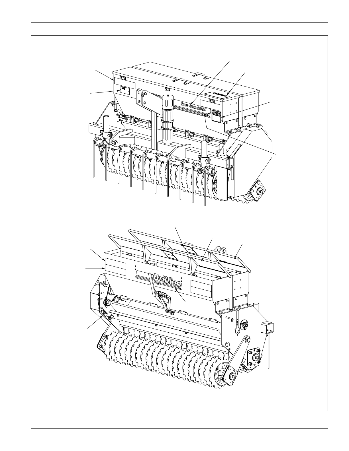
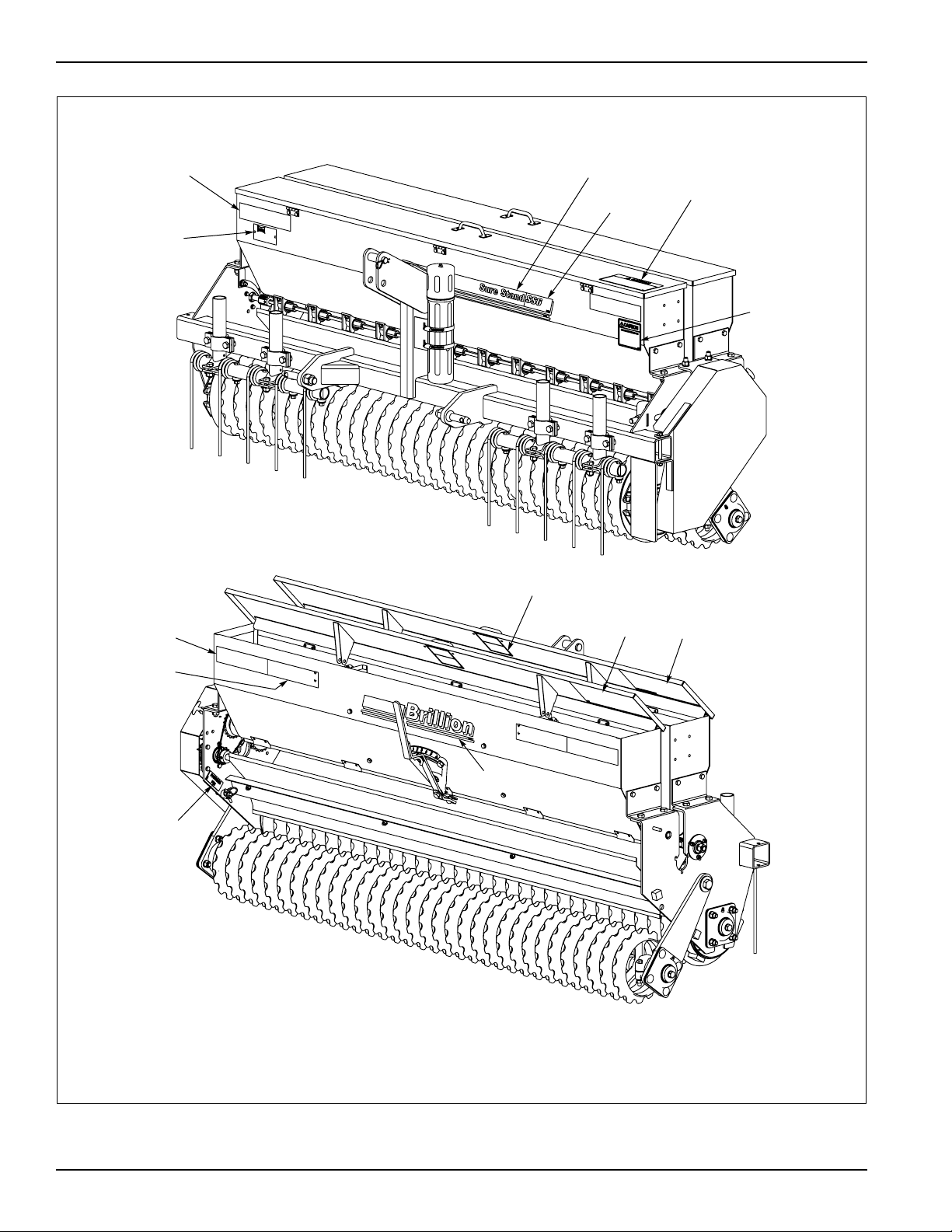
Examine safety decals and be sure you have the correct
safety decals for the implement. See Safety Sign and
Locations for decal locations. See Figures 1-2, 1-3 and
1-4.
Order replacement decals through your Brillion dealer.
Keep these signs clean so they can be observed readily.
It is important to keep these decals cleaned more
frequently than the implement. Wash with soap and water
or a cleaning solution as required.
Replace decals that become damaged or lost. Also, be
sure that any new implement components installed
during repair include decals which are assigned to them
by the manufacturer.
When applying decals to the implement, be sure to clean
the surface to remove any dirt or residue. Where
possible, sign placement should protect the sign from
abrasion, damage, or obstruction from mud, dirt, oil etc.
Keep Riders Off of Machinery
DANGER
Transporting Safety
IMPORTANT
It is the responsibility of the owner/operator to
comply with all state and local laws.
When transporting the implement on a road or highway,
use adequate warning symbols, reflectors, lights and
slow moving vehicle sign (purchased separately), as
required. Slow moving tractors and towed implements
can create a hazard when driven on public roads. They
are difficult to see, especially at night.
Do not tow an implement that, when fully loaded, weighs
more than 1.5 times the weight of the towing vehicle.
Carry reflectors or flags to mark tractor and implement in
case of breakdown on the road.
Do not transport at speeds over 20 MPH under good
conditions. Never travel at a speed which does not allow
adequate control of steering and braking. Reduce speed
if towed load is not equipped with brakes.
Avoid sudden stops or turns because the weight of the
implement may cause the operator to lose control of the
tractor. Use a tractor 1.5 times heavier than the
implement.
Use caution when towing behind articulated steering
tractors; fast or sharp turns may cause the implement to
shift sideways.
Special notice - read and thoroughly understand.
Proceed with caution. Failure to heed caution
may cause injury to person or damage product.
Proceed with caution. Failure to heed warning will
cause injury to person or damage product.
Proceed with extreme caution. Failure to heed
notice will cause injury or death to person and/or
damage product.
• Do not allow extra riders on tractor or a
machine. Riders could be struck by foreign
objects or thrown from the implement.
• Never allow children to operate equipment.
• Keep bystanders away from the implement
during operation.

SAFETY INFORMATION
1-3
Keep clear of overhead power lines and other
obstructions when transporting. Know transport height
and width of your implement. Refer to transport
dimensions. See Table 4-2.
Attaching, Detaching and
Storage
• Do not stand between the tractor and implement when
attaching or detaching implement unless both are
incapable of moving.
• Before applying pressure to the hydraulic system, be
sure all connections are tight and that hydraulic lines
and hoses are not damaged.
• Lower implement to the ground when not in use so
that the shanks are taking the load.
• Block implement so it will not roll when unhitched from
the tractor.
• Relieve pressure in hydraulic lines before uncoupling
hydraulic hoses from tractor.
NOTE
On most tractors relieving hydraulic pressure can be
accomplished by operating valves after the engine is
stopped.
Maintenance Safety
Block the implement so it will not roll when working on or
under it to prevent injury in case of hydraulic failure or
inadvertent lowering by another person.
Do not make adjustments or lubricate implement while it
is in motion.
Make sure all moving parts have stopped and all system
pressure is relieved.
Understand all maintenance procedures before doing the
work. Use the proper tools and equipment.
High Pressure Fluid Safety
Escaping fluid under pressure can be nearly invisible and
have enough force to penetrate the skin, causing serious
injury. Use a piece of cardboard, rather than hands, to
search for suspected leaks.
Any fluid injected into the skin must be surgically
removed within a few hours or gangrene may result.
Avoid the hazard by relieving pressure before
disconnecting hydraulic lines.
NOTE
On most tractors relieving hydraulic pressure can be
accomplished by operating valves after the engine is
stopped. Also, the implement should be lowered to the
ground so that the shanks are taking the load.
Wear protective gloves and safety glasses or goggles
when working with hydraulic systems.
Protective Equipment
• Wear protective clothing and equipment.
• Wear clothing and equipment appropriate for the job.
Avoid loose fitting clothing.
• Because prolonged exposure to loud noise can cause
hearing impairment or hearing loss, wear suitable
hearing protection, such as earmuffs or earplugs.
Chemical Safety
Agricultural chemicals can be dangerous.
Improper use can seriously injure persons, animals,
plants, soil and property.
Read chemical manufacture’s instructions and store or
dispose of unused chemicals as specified.
Handle chemicals with care and avoid inhaling smoke
from any type of chemical fire.
Store or dispose of unused chemicals as specified by the
chemical manufacturer.
Prepare for Emergencies
• Keep a First Aid Kit and Fire Extinguisher handy.
• Keep emergency numbers for doctor, ambulance,
hospital and fire department near the phone.

1-4 7K555
SAFETY INFORMATION
Figure 1-2: Decals
7
3
2
1
4
6
5
8
PLANTING RATES FOR SEED METER (FRONT BOX) IN POUNDS PER ACRE
CALIBRATION 1. Rates are for 13-Tooth Driver Sprocket.
2. Rates are intended as a guide only. Variations in size and cleanliness will affect rates.
Check acreage & pounds of seed used for best results.
Machine May Be Calibrated for Unlisted Seed as Follows:
1. Remove chain between 17 Tooth and 19 Tooth Sprockets.
2. Raise machine & lock in transport position.
3. Place a canvas or tarp in position to catch seed.
4. Turn 3/4 Hex on Sprocket shaft 795 revolutions counter-
clockwise. 159 turns be used if results are adjusted as
shown in Step #5.
5. Weigh seed for approximate planting rate.
Multiply weight by 5 if only 159 Turns were used.
7K433 For 6 Foot Sure Stand Seeder
-1 578111213
1* 8* 13 20 25 31 36 43
4 8 11 15 20 24 27 31
1 2 3 4 5 6 7 8
4 8 15 23 27 35 41 46
1 7 12 17 23 27 32 36
4 8 15 24 29 36 41 48
411 17 24 36 43 53 61
1 4 5 8 11 13 16 17
15 81317 23 2529
411 15 23 29 36 41 48
4 8 13 20 29 33 41 51
-1 4 5 7 8 1112
412192535414958
4 8 13 17 23 28 32 36
1 7 11 15 19 24 27 31
4 8 17 23 31 39 48 52
1 7 12 17 24 29 36 41
4 8 15 23 27 36 43 48
15 81319 23 2529
411 17 25 32 41 49 55
111 17 23 29 37 44 52
4 8 13 19 25 32 39 46
411 17 24 31 37 44 52
1 4 7 8 11 12 13 15
14 71112 15 1723
- 4 7 8 12 15 19 23
4 7 12 19 24 31 37 43
Indicator Setting
Alfalfa (Uncoated
Bahia
Bermuda (Hulled)
Birdsfoot Trefoil (Broadleaf)
Blue Grass (Kentucky)
Blue Grass (Park Kentucky)
Blue Grass (Sherman Big)
Canola
Centipede
Clover (Alsike, Ladino, Sweet, Red)
Clover (Alyce, Calif. Bur., Crimson, Hubam)
Crested Wheat
Crown Vetch
Flax
Harding Grass
Klein Grass
Lespedeza (Korean Unhulled)
Lespedeza (Korean Hulled)
Lespedeza (Sericea Unhulled)
Lespedeza (Sericea Hulled)
Love Grass (Weeping)
Love Grass (Sand)
Millet
Red Top
Reed Canary Grass
Switch Grass (Cleaned and Hulled)
Timothy
*WILL CRACK SOME SEEDS AT
THESE SETTINGS
NOT RECOMMENFDED: LENTILS,
SORGUM, SUDAN GRASS
Tightener
Driver
13T
Idler 3/4
Hex
23T
26T
18T
19T
13T
18T
17T
34T
PARKING
PIN
9J301
WARNING
MOVING PART HAZARD
TO PREVENT SERIOUS INJURY FROM
MOVING PARTS:
KEEP COVERS CLOSED DURING OPERATION.
DO NOT ALLOW ANYONE TO RIDE OR CLIMB
MACHINE DURING OPERATION.
KEEP OBSERVERS AWAY.
2K123
9
CAUTION
1. DO NOT LUBRICATE, ADJUST OR REPAIR WHEN MACHINE IS IN MOTION.
2. DO NOT TOW OR TRANSPORT FASTER THAN 15 MILES PER HOUR.
3. DO NOT RIDE OR ALLOW OTHERS TO RIDE ON THE MACHINE.
4. BLOCK UP ALL HYDRAULICALLY OR MECHANICALLY RAISED COMPONENTS TO PREVENT
UNINTENDED LOWERING OR LOWER THE MACHINE TO THE GROUND TO MAKE ADJUSTMENT
OR REPAIRS OR WHEN NOT IN USE.
5. KEEP ALL PERSONS AWAY FROM MACHINE DURING HITCHING AND OPERATING.
6. SLOW DOWN BEFORE MAKING SHARP TURNS OR USING THE BRAKE.
DRIVE SLOWLY OVER ROUGH GROUND, SIDE HILLS, AND AROUND CURVES TO AVOID TIPPING.
7. COMPLY WITH ALL LAWS WHEN TRANSPORTING THE MACHINE ON PUBLIC ROADWAYS.
8. INSTRUCT ALL OPERATORS IN THE SAFE OPERATION OF THE MACHINE.
REVIEW THE OPERATOR’S MANUAL FOR CORRECT PROCEDURES.
9. BLOCK IMPLEMENT TO PREVENT MOVEMENT WHEN UNHITCHED FROM TRACTOR.
10. KEEP ALL GUARDS AND SHIELDS IN PLACE WHILE MACHINE OR PARTS ARE IN MOTION.
8J310
CAUTION
BE SURE TO ENGAGE
PARKING PIN ON LEFT END OF
FRAME BEFORE UNHITCHING
TRACTOR. OTHERWISE
FRAME WILL TIP BACKWARDS
ABOUT FRONT AXLE 9J302
Sure-Stand
4K401
SS6
4K401
SS5
4K401
SS4
4K401
12
10
11

SAFETY INFORMATION
1-5
Figure 1-3: SSP4 Decals
,'3ODWH

1-6 7K555
SAFETY INFORMATION
Figure 1-4: SSP5 and 6 Decals
,'3ODWH

2-1
Chapter 2
Assembly of Optional Equipment
The intent of this chapter is to provide instructions
allowing you to safely and correctly assemble your
Brillion product.
CAUTION
Agitator Blades (Optional Cage
or Brushes)
Agitator blades are supplied as standard on your
seedbox. While in operation, they should operate leaving
a slight clearance with the bottom of the seed box.
Agitator brushes (optional) in the seed box sweep the
bottom of the box to control the flow of seed. However, if
they exert too much pressure on the bottom of the box,
chain breakage and excessive brush wear can possibly
result. To overcome excessive pressure of the brushes
on the bottom of the box, the bolts holding the triangular
cast iron bearings can be loosened and the bearings
raised to reduce excessive drag. The holes in the bearing
are slightly larger than the bolts holding them, thus
making an adjustment possible.
Cage agitator (optional) operates similar to blades.
IMPORTANT
Before proceeding with any agitator installation, be
sure to determine the direction of shaft rotation on
your particular seeder model. See Figure 2-1.
Figure 2-1: Shaft Rotation
Changing Agitator Kits
1. Remove two 5/16-18 x 1-1/4 bolts (inside the box)
which hold bearing on the right end of the right seed
box. See Figure 2-2.
2. Slide shaft out of right end.
3. Agitators should be installed with careful attention
paid to the direction of shaft rotation. This is
especially important if you are installing brush
agitators as they will be damaged if they are run
backwards. Blade agitators will not be damaged if
they run ”backwards”, but the seed rate will be
reduced.
4. With the agitators properly seated in the boxes,
replace the drive shafts. Replace washers as needed
for fit.
5. Check to be sure agitators rotate freely. Some
seeders may have bolts extending into the seed box
causing interference. These bolts will need to be
shortened.
Do not work on or under this implement unless
securely blocked and supported by a hoist or
tractor or by other sufficient means!
)52172)
0$&+,1(
2ULHQWDWLRQRIEODGHRUEUXVKDJLWDWRU
ZUHVSHFWWRVKDIWURWDWLRQ
5RWDWLRQ
RI6KDIW

2-2 7K555
ASSEMBLY OF OPTIONAL EQUIPMENT
Figure 2-2: Agitators
Lift Sling Kit (Optional)
1. If not already assembled to the machine, attach a
mounting bracket to each side of machine at the
center holes of the right and left end plates. (A strap
may need to be added to one side to equalize the
thickness of plates on the both sides of the machine.)
2. Attach the lift sling to mounting brackets with 5/8-11 x
1-1/2” bolts and stover nuts provided in kit. See
Figure 2-3.
3. Slide stabilizer into frame tube and secure with clevis
pin and hairpin cotter.
CAUTION
6KDIWRXW
ULJKWHQG
&KHFN
6KDIW
5RWDWLRQ
'LUHFWLRQ
%UXVK
$JLWDWRU
$VVHPEO\
&DJH
$JLWDWRU
/RFNZDVKHU´
1XW
,QWHUPHGLDWH
%HDULQJ
&RWWHU3LQ
[´
(QG
%HDULQJ
ZEXVKLQJ
:DVKHU
:DVKHU
%ROW
[´
)52172)
0$&+,1(
Stay clear of machine when using the lift sling to
lift or move it. Do not work under machine using
only the sling to support it. Keep observers away.

ASSEMBLY OF OPTIONAL EQUIPMENT
2-3
Figure 2-3: Lift Sling Kit
(;,67,1*
+$5':$5(
0RXQWLQJ%UDFNHW
0RXQWLQJ%UDFNHW
+DLUSLQ
&RWWHU
&OHYLV3LQ
%ROW
[
6WDELO]HU
1XW
%ROW
[
1XW
/LIW6OLQJ
(;,67,1*
+$5':$5(
(;,67,1*
+$5':$5(

2-4 7K555
ASSEMBLY OF OPTIONAL EQUIPMENT
Acre Meter (Optional)
The acre meter, consisting of three main parts; the acre
meter, the pick-up, and the magnet wheel, is mounted on
the left front side of the seedbox.
1. Drill 13/32” holes into seedbox at location shown.
See Figure 2-4.
2. Next, use 3/8-16 x 1” bolts, lockwashers, and nuts to
attach the bracket which holds the acre meter, as
shown, onto the left front of the seedbox.
3. Mount the acre meter onto this bracket with #10-24 x
1” bolts, lockwashers and nuts.
4. Then run the wire from the bottom of the meter down
the side of the seed box and along its left side. Use
mounting bases to hold the wire in place. Direct it
across the plate which attaches the seedbox to the
end plate. See Figure 2-4.
Figure 2-4: Acre Meter (1 of 2)
1XW´
'ULOO´
+ROHV
/RFNZDVKHU´
/RFNZDVKHU
1XW
3LFNXS%R[
&DEOH
$FUH0HWHU
&DEOH
0RXQWLQJ
%DVH
%ROW
;´
)URQWRI
6HHGHU
$FUH0HWHU
$VVHPEO\
;´
%ROW

ASSEMBLY OF OPTIONAL EQUIPMENT
2-5
5. At the rear of the seeder, mount the L-shaped
bracket to the end plate with a 5/8-11 x 1-1/2” bolt
and locknut as shown. See Figure 2-5. The small
shoulder on the bracket should butt up against the
end plate of the seeder frame. On top of this bracket
mount the pickup with two #8-32 x 1-1/4” bolts, flat
washers, lockwashers, and nuts.
6. Extend its longer wire up toward the side of the
seedbox to meet the wire from the acre meter. Attach
its shorter wire to the ground on the bracket.
(Remove paint under the terminal to assure a good
electrical connection.)
7. Press the magnet wheel firmly onto the shaft.
IMPORTANT
There should be a gap of 1/8” between the pickup
and the magnet wheel.
8. Plug the acre meter cable into the pick-up box cable.
Figure 2-5: Acre Meter Rear Installation (2 of 2)
/RFNZDVKHU
*URXQG
:LUH
%ROW
;´
/RFNZDVKHU´
6WRYHU1XW´
%UDFNHW
0DJQHW
:KHHO
5HDU2I
6HHGHU
3LFNXS
1XW
%ROW
;´
1XW
´*DS
3LFNXS%R[
&DEOH
%ROW
;´
)ODW:DVKHU

2-6 7K555
ASSEMBLY OF OPTIONAL EQUIPMENT
Page Intentionally Blank

3-1
Chapter 3
Operation
Seeder Operation
This chapter covers the basic operation and usage
procedures for the Landoll Brillion Sure Stand Seeder.
Be sure to read and understand the Safety Procedures
and Cautions starting on page 1-2.
WARNING
Figure 3-1: Parking Pin
Parking Pin
When hooking up the seeders:
1. Attach the tractor.
2. Remove the Klik pin, pull the parking pin into outer
position, replace the Klik pin. See Figure 3-1.
When unhooking the seeders:
1. Remove the Klik pin, push in the parking pin, replace
the Klik pin. See Figure 3-1.
2. Disconnect the tractor.
To prevent the implement from tipping backward
on the frame, disengage the parking pin only
when the seeder is fully attached to the tractor.
Be sure to observe the following sequences.
Parking Pin
Klik Pin
(Use This Hole When
Disconnected From Tractor)
(Use This Hole When Connected
To Tractor)

3-2 7K555
OPERATION
Seed Rate Adjustment- Front
Box
Adjusting Seed Cups:
All cups must be set the same in order to seed uniformly.
To check, set the inner and outer adjusting nuts to close
the seed cups. All cups should be completely closed. If
not, individual cups can be adjusted by loosening their
mounting bolts, moving the cups, and then re-tightening.
See Figure 3-2.
Pointer Adjustment
With cups completely closed, pointer should point to
groove in hex shaft marked “0”. If it does not,
adjust the nuts which clamp the pointer spring bolt to the
frame end plates. See Figure 3-2.
Figure 3-2: Seed Rate Adjustment (Front Box)
Secure
Pointer By Holding
Firmly between Screw Head & Nut
Pointer
Pointer must read
“0” when cups are
closed.
Mounting Bolt
Individual
Seed Cup

OPERATION
3-3
WARNING
Seed Rate Adjustment - Rear
Agitator Box
Adjusting the Box Slide:
When properly adjusted, the holes in the slide should line
up with the holes in the box, with the control handle set at
“6”. To make an adjustment, loosen the control handle on
the box, move the slide until the holes line up. See
Figure 3-3.
When the handle is moved to ‘0’ the holes in the box
should be completely covered. If the holes are not
covered, loosen the three bolts holding the seedmeter
casting and shift it slightly so that the “0” mark is farther
from the control handle. Retighten the bolts. Move the
control handle to “0”. Holes in the box should then be
completely covered. See Figure 3-4.
Figure 3-3: Agitator Box Control Handle
Figure 3-4: Adjusting the Box Slide
• To prevent damage to the seed meters, do not
apply excessive force to adjusting nuts.
Failure to do so may result in seed being
pinched between the cut-off and washer
inside the seed cup.
• Do not close the meters more than 1/8” when
there is seed in the meters without rotating
the seed shaft. This prevents damage to the
rotating washers and retainer rings in the
seed meters.
• Do not attempt to open the meters more than
1”. (Feed rolls could become disengaged
from the washer in the seed cup.) Wing Nut
,IWKHKROHVDUHQRWFRYHUHG
ZKHQVHWDWORRVHQWKHVH
WKUHHEROWVKROGLQJWKH
VHHGPHWHUFDVWLQJDQGVKLIW
LWVOLJKWO\5HWLJKWHQWKH
EROWV
6HWDW³´
+ROHV VKRXOGOLQH
XSFORVHG 6HWDW³´
+ROHV VKRXOGOLQH
XSRSHQ

3-4 7K555
OPERATION
Seed Rate Calibration
The provided charts were determined by laboratory tests
on various samples. To find rates for specific seed lots or
to calibrate for unlisted seeds, proceed as shown on the
seed chart.
Machine May Be Calibrated for Unlisted Seed as Follows:
1. Remove the chain between 17 Tooth and 19 Tooth
Sprockets. See Figure 3-5.
2. Raise the machine and lock in transport position.
3. Place a canvas or tarp in position to catch seed.
4. Turn the 3/4 Hex on sprocket shaft counterclockwise
(CCW).
1195 Revolutions for 4 Foot Seeder.
955 Revolutions for 5 Foot Seeder.
795 Revolutions for 6 Foot Seeder.
5. Weigh the seed for approximate planting rate.
6. Fewer turns may be used if results are adjusted by
turning 3/4 Hex on sprocket shaft counterclockwise
(CCW).
239 Revolutions for 4 Foot Seeder.
191 Revolutions for 5 Foot Seeder.
159 Revolutions for 6 Foot Seeder
and multiplying the weight by 5.
PLANTING RATES FOR SEED METER
(FRONT BOX) IN POUNDS PER ACRE:
• Rates are for the 13-Tooth Driver Sprocket.
• Rates are intended as a guide only. Variations in size
and cleanliness will affect rates. Check acreage and
pounds of seed used for best results. See Table 3-1
and Table 3-2.
Figure 3-5: Chain Calibration
Table 3-1: Planting Rates for 4 and 5 Foot Seeders
7227+
7227+
7227+
,'/(5
+(;
7227+
7227+
7227+
,'/(5
7227+7227+
7227+
'5,9(5
7227+
,'/(5
Indicator Setting 1 2 3 4 5 6 7 8
Alfalfa (Uncoated
Bahia
Bermuda (Hulled)
3
1
3
6
5
6
12
9
12
17
13
18
21
17
21
26
21
27
30
24
30
35
27
36
Birdsfoot Trefoil (Broadleaf)
Blue Grass (Kentucky)
Blue Grass (Park Kentucky)
3
1
1
8
3
4
13
4
6
18
6
10
27
8
13
32
10
17
39
12
19
46
13
21
Blue Grass (Sherman Big)
Canola
Centipede
-
1*
3
1
6*
6
4
10
8
5
15
12
6
19
15
8
23
18
9
27
21
10
32
23
Clover (Alsike, Ladino, Sweet, Red)
Clover (Alyce, Calif. Bur., Crimson, Hubam)
Crown Vetch
3
3
-
8
6
1
12
10
3
17
15
4
21
21
5
27
25
6
30
30
8
36
38
9
Flax
Harding Grass
Crested Wheat
3
3
1
9
6
5
14
10
8
19
13
12
26
17
14
30
21
18
37
24
21
44
27
23
Klein Grass
Lespedeza (Korean Unhulled)
Lespedeza (Korean Hulled)
3
1
3
6
5
6
13
9
12
17
13
17
23
18
21
30
21
27
36
27
32
39
30
36
Lespedeza (Sericea Unhulled)
Lespedeza (Sericea Hulled)
Love Grass (Weeping)
1
3
1
4
8
8
6
13
13
10
19
17
14
24
21
17
30
28
19
37
33
21
41
39
This manual suits for next models
2
Table of contents
Other Landoll Seeder manuals

Landoll
Landoll Brillion LSP5 User manual

Landoll
Landoll Brillion SSB User manual

Landoll
Landoll BRILLION SL Series User manual

Landoll
Landoll Brillion Turfmaker III Series User manual

Landoll
Landoll Brillion 4630-36 Series User manual

Landoll
Landoll Brillion SS16 User manual

Landoll
Landoll Brillion Turfmaker II Series User manual

Landoll
Landoll SSB-8 User manual

Landoll
Landoll Brillion LSP5 User manual