Fiessler AKAS LC-II M User manual

Fiessler Elektronik GmbH & Co. KG
Kastellstr. 9 D-73734 Esslingen
Press Brake Protection System safety category 4
AKAS®LC-II M
AKAS®LC-II F
Operating Instructions
CONTENTS:
Safety Instructions
Application
Instruction for use
Mechanical data
Electrical connection
Putting into operation
FIESSLER
E L E K T R O N I K
Telefon: 0711 / 91 96 97-0 Internet: http://www.fiessler.de
EC type examination certified
AKAS®-LC-II M
AKAS®-LC-II F
Zertifiziertes QM-System
nach DIN ISO 9001:2000
Doku Nr. 995Stand 1.12.2011 / Aui
E L E K T R O N I K

2
Contents
chapter contents page
1Indicator lights on Frontpanel and switches for safe operation AKAS®-LC II F………………… 3
1.1 Indicator lights on Frontpanel and switches for safe operation AKAS®-LC II M ………………… 4
2General Safety Instructions …….……………………………………………………………………………………… 5
2.1 Prerequisites for using the press brake protection AKAS® ……………………………………………………………………………… 6
3 Description and fields of application for the equipment……..……………………………………………………………… 7
3.1 General Instructions ………………………………………………………………………………………………………………………… 7
3.2 Function Description / Characteristics …………………………………………………………………………………………………… 8
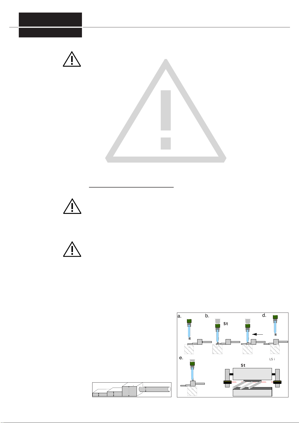
3.3 Function description during bending of flat sheet metal / bending of wavy sheet metal …………………………………………… 9
3.4 Function description during Box bending / bending of small items …………………………………………………………………… 10
4 Mechanical data, dimension drawings ……………………………………………………………………………………… 11
4.1 AKAS®-LC II M / -F ………………………………………………… ……………………………………………………………………… 11
5Mounting…………………………………………………………………………………………………………………… 12
5.1 How to proceed during the mounting of the AKAS® -system / Fiessler Suspension Devices …………………………………… 12
5.2 1. Overrun Traverse Measuring ……………………………………………………………………………………………… 13
5.3 2. Design of a Mechanical Suspension Device - void if Fiessler Suspension Devices are used ……………………… 14
5.4 3. Mounting of the suspension devices at the ram ………………………………………………………………………… 14
5.5 4. Mounting of the AKAS® components at the suspension devices…………………………………………………… 15
5.6 5. Connection the AKAS® - wiring diagrams: see chapter 6 …………………………………………………………… 15
5.7 6. Adjustment of the AKAS® during first installationn …………………………………………………………………… 16
5.8 7. Adjustment of the distance of the AKAS® from the bending punch ………………………………………………… 20
5.9 8. Function Verification of all electrical connections in view of the safety classs 4 requirements………………… 21
5.10 9. Self-Acting Overrrun Traverse Test ………………………………………………………………………………………… 21
6Electrical connections -Descriptions / wiring diagrams ………………………………………………………… 22
6.1 Electrical Data ……………………………………………………………………………………………………………………………… 22
6.2 Instructions for Integrating the AKAS® inti the machine control system ……………………………………………………………… 23
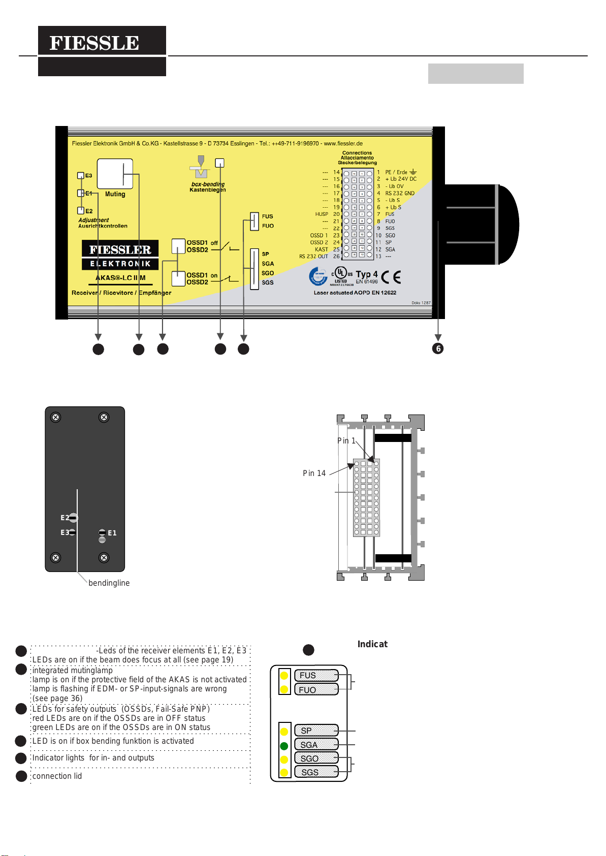
6.4 AKAS®-LC II M …………………………………………………………………………………………………………………………… 24
Functions / Terminals …………………………………………………………………………………………………………………… 24
Connection ………………………………………………………………………………………………………………………………… 25
6.5 AKAS®-LC II F …………………………………………………………………………………………………………………………… 26
Functions / Terminals …………………………………………………………………………………………………………………… 26
Connection example: safety monitoring of the machine by AKAS®-...F ……………………………………………………… 28
6.5.1 AKAS®-...F selectable Safety functions …………………………………………………………………………………………… 29
1. Operation with additional safety control ………………………………………………………………………………………… 29
2. Monitoring of the Foot Pedal ………………………………………………………………………………………………………… 29
Connection: 2 Foot Pedals for 2 Operators …………………………………………………………………………………… 29
3. Easy-braking if the Foot Pedal is released (Delayed Foot Pedal Reaction) …………………………………………………… 29
4. Overrun Traverse Control ……………………………………………………………………………………………………………… 29
5. Monitoring of the Stop Valves (EDM) ………………………………………………………………………………………………… 30
6. Monitoring of the door- and the Emergency OFF-circuits, Emergency-OFF of the Motor-driven rear stoppers …………………30
Connection: Reset Button wiring for the rear protective grid if operated without EDM …………………………………… 30
Connection: Safety light Grid ( equivalent switching) as rear guard ………………………………………………………… 31
Connection: Safety light Grid ( antivalent switching) as rear guard ………………………………………………………… 31
7. Installation operation / protection by monitored slow speed wiithout activated protective field ……………………………………… 32
Connection: when equivalent switching door contacts are used …………………………………………………………… 32
Connection: when antivalent switching door contacts are used ……………………………………………………………… 32
8. Information about the traverse in slow speed -Connection of traverse measuriung device …………………………………… 33
9.Enhancement of Switching-over tolerances of the valve position monitors …………………………………………………… 33
6.5.2 Programming of the safety functions by Hex switches ……………………………………………………………………………… 34
6.6 Displaying outputs, Indicator-LEDs……………………………………………………………………………………………………… 36
-Muting lamp , adjustment control LEDs,Indicator-LEDs ……………………………………………………………………… 36
-Outputs via serial RS232-interface ……………………………………………………………………………………………… 37
7 Service / Maintenance / Warranty ……………………………………………………………………………………… 40
8 Order Codes ……………………………………………………………………………………………………………… 41
9 AKAS®-Inspection sheet………………………………………………………………………………………………… 42
10 Declaration of Conformity...…………………………………………………………………………………………… 43
11 Terms..................................................................................................................................................... 44
Doku Nr. 995 Stand 1.12.2011 / Aui
FIESSLER
E L E K T R O N I K

3
Indicator lights on Frontpanel and switches for safe operation 1
Doku Nr. 995 Stand 1.12.2011 / Aui
AKAS®LC-II F 1.1
1
2
3
4
5
6
26
3
4
5
6
7
8
9
10
11
12
13
25
24
23
22
21
20
19
17
16
15
14
18
2
1
ajustment controll-Leds of the receiver elements E1, E2, E3
LEDs are on if the beam does focus at all (see page 19)
integrated mutinglamp
lamp is on if the protective field of the AKAS is not activated
lamp is flashing if EDM- or SP-input-signals are wrong
(see page 36)
LEDs for safety outputs (OSSDs, Fail-Safe PNP)
red LEDs are on if the OSSDs are in OFF status
green LEDs are on if the OSSDs are in ON status
LED is on if box bending funktion is activated
Indicator lights for in- and outputs
connection lid
SP
SGA
SGO
SGS
RXOK2
RXOK1
NLW
NA1
NA3
NA2
FUS
FUO
EDMO
EDMS
Indicator lights for in- and outputs
(
see
p
a
g
e 36
Outputs for
release of rear sto
pp
ers
Input for Overruntraverse controll
Inputs for control of protective grids or
doors and emergency-off circuits
Inputs for press start / stop
(
release of closin
g
stroke
)
Input for stop contactor control
Input for safety point
Output for demand for slow speed
Input for position control in slow speed
5
view after removing the connection lid
on the receiver
view of the receiver elements
hex-switch 4
hex-switch 3
hex-switch 2
hex-switch 1
(see page 34,35)
connector plug
E3 E1
bendingline
E2
FIESSLER
E L E K T R O N I K
E L E K T R O N I K
1234 5 6
Pin 1
Pin 14

4
Doku Nr. 995 Stand 1.12.2011 / Aui
LEDs and operating elements 1
AKAS®LC-II M 1.2
26
3
4
5
6
7
8
9
10
11
12
13
25
24
23
22
21
20
19
17
16
15
14
18
2
1
SP
SGA
SGO
SGS
FUS
FUO
Indicator lights for in- and outputs
(see page 36
Inputs for press start / stop
(release of closing stroke)
Input for safety point
Output for demand for slow speed
Input for position control in slow speed
5
view after removing the connection lid
on the receiver
view of the receiver elements
connector plug
1
2
3
4
5
6
ajustment controll-Leds of the receiver elements E1, E2, E3
LEDs are on if the beam does focus at all (see page 19)
integrated mutinglamp
lamp is on if the protective field of the AKAS is not activated
lamp is flashing if EDM- or SP-input-signals are wrong
(see page 36)
LEDs for safety outputs (OSSDs, Fail-Safe PNP)
red LEDs are on if the OSSDs are in OFF status
green LEDs are on if the OSSDs are in ON status
LED is on if box bending funktion is activated
Indicator lights for in- and outputs
connection lid
bendingline
E3 E1
E2
FIESSLER
E L E K T R O N I K
E L E K T R O N I K
1234 5 6
Pin 1
Pin 14

FIESSLER
E L E K T R O N I K
This is the operating instruction for the AKAS® models AKAS®-LC IIM, AKAS®-LC IIF
Special instructions for each model are provided with its individual model marking.
Attention is drawn to all safety instructions by this symbol. Particular attention must be paid to such instructions.
These operating instructions provide to the user important information concerning the correct use of the AKAS®.
These instructions are a component of the light barrier concerned. It is essential that they are easily available at
the location where the safety light barrier is installed. Before the initial operation of the AKAS®, all requirements
detailed in these operating instructions must be observed. Other relevant regulations and the requirements of
the employers' liability insurance associations have also to be complied with.
Mounting, initial operation and maintenance may only be performed by qualified persons.
Light barriers do not protect anybody from machine-caused flying objects.
The AKAS® protects fingers and hands that hold the sheet during the operation. Therefore it does not protect
during any fast engagement between the bending punch and the matrix short time before those are
closed. The protection function of the system is cancelled when the Muting lamp is on.
The front beams E1 which are turned to the operator before the bending line do not protect, if the box-
bending function has been activated earlier.
With the integration of a AKAS ® safety system, the standard should be strictly complied with the
European Standard (EN12622).
Protection circuits and Emergency can only stop the opening movement when the movement is
interupted with the RXOK outputs.
5
Read the operating in-
structions
Qualified Personnel
Safety warning
A-Test:
putting into operation
B-Test: daily check
(at least every 24 hours)
Safety Instructions
Please observe always
2
Doku Nr. 995 Stand 1.12.2011 / Aui
A-TEST when putting into operation
The setting must be done in a way that the following test will be passed:
- The B-Test must be done for safety reasons each 5 times on the left end and on the right end of the
upper tool.
- The press brake must be equipped completely with the heaviest upper tool.
- Start of the closing movement from the maximum top dead centre (T.D.C)
At the beginning of each shift and after each change of tools, the AKAS® press brakes protection
must be checked as follows (see also pr EN 12622.2002):
Test must be carried out at both left and right ends of the bending punch.The punch must not touch the
step-shaped test rod.
a.) Place the test piece in position "10"on the lower tool. Select the box bending function if you use a
system of the AKAS®3... product family.
Now start the close down movement.
b.) The press brake stops.
c.) The test piece must be placed in position "15" under the upper tool. In this position ("15") the test
piece may not touch the upper tool.
d.) Drive up the press brake. Place the the test piece in position "35"on the lower tool. Select the nor-
mal bending function if you use a system of the AKAS®3... product family.
Now start the close down movement.
e.) The press brake must be stopped in a way that the test piece ("35") may not touch the upper tool.
f.) Move the test piece ("14") along the tip of
the upper tool. The AKAS®-II receiver has to
remain in the interrupted (LS unterbrochen /
interrupted = red LED) state.
fig. 5/ 2
a.
b.
c.
d.
e. f.
Stop
Stop
LS interrup-
ted
10 15
35 14
fig. 5/1

1.Use onlytoolswiththe same heightinthe same fixingonthe press. Allutilizedtoolsmusthave one common
bending line.
2. Stoppers, which are mounted at the matrix, lead to a premature switching-off of the downward
movement.
3. The maximum allowable overrun traverse of the machine:10mm bei AKAS®-LC II...
Thepressmusthaveanautomatedoverruntraversecontrolforthefirststroke.Ifnot,itcanberealisedby
the AKAS®-...F and a cam controller or by the Fiessler AMS-system . Before the initial start-up, the overrun
traverse must be checked either by using the test rod (see page 5) or by using an Overrun Traverse measu-
ringdevice.(uponcustomer'srequest, FiesslerElektronikwill performtheOverrun TraverseMeasuringon thecustomer'smachi-
ne.)Iftheresultsof10consecutivemeasurementsarelargerthan10mmthefastspeedmustbereduced.
4.Duetothemissing sychronizationduringfastspeed, AKAS®cannotbeusedfor twomachinesaligned in
parallel (e.g. "tandem press brake") .
5. Muting signal If a light beam is interrupted by the sheet which is to be bent, the AKAS® would stop the working
stroke immediately. Therefore the AKAS® must be muted before it gets interrupted by the sheet. Likewise, slightly
uneven sheetsshouldnotleadeither toanunintendedswitching-off ofthecuttingmovement.Fromanopeningof <
13-22mm(accordingtooverruntraverseofthepress)thecontrolsystemofthemachinemustsendaMutingsignalto
thereciever.Thenthecontrol system of the machinemustreliablyguaranteeaccording to safety category4,
that from this time the stroke speed is < 10 mm/s.
6.The protection ofa pressbrake bythe AKAS® doesnot permit abending in thebottom of abox insideone
box in fast speed.
7. The AKAS® does not protect: -if the machine is only run in the work speed, or AKAS will be
interrupted during fast speed and the stroke will be continued in
work speed
-if the overrun traverse of the press brake is too long
-from squeezing during the bending operation
-if the mutinglamp is constantly on
8.
The hazardous state of the machine must be terminated by the sensor function.
9.The safetylevel (class 4) of the accident preventing lightbarrier should at least correspondtothe safety le-
vel of the control system of the machine.
10. Laser beams may be deviated due to air currents, this may cause unwanted and unforeseen machine
stops. Therefore the machine must be erected at a place free of air currents.
Acceptancetest:theinstallationacceptancetestandinspectionsshouldbecarriedoutbyacompetentpersoninpos-
session of all the information supplied by the manufacturer of the machine and the ESPE.
Uponcustomer'srequest,FiesslerElektronikwillperformtheinitialacceptanceaswellastheannualtest.Additional-
ly, customer training seminars on how to execute annual tests will be conducted at regular intervals.
Themachineownermustmakesurethatacompetentpersonisassignedtocheckthelightbarrierannually.Thisper-
soncanbeanemployeeeitherfromthelight-barriermanufacturerorfromtheoperator'sstaff.Theannualtestshallbe
executed according to the inspection sheet on pae 48.
Safety Instructions
Acceptance
Annual Inspection
6
2
fig. 6/ 1 fig. 6/ 2
Prerequisites for using the press brake protection AKAS® 2.1
Doku Nr. 995 S tand 1.12.2011 / Aui
FIESSLER
E L E K T R O N I K

Description and fields of application for the equipment
General Instructions
7
without Support:
AKAS®-LC II M,
AKAS®-LC II F
Serial Num-
bers:AKAS®-LC II M
AKAS®-LC II F
3
3.1
Matrix
Bending punch
fig. 7/ 4
Doku Nr. 995 S tand 1.12.2011 / Aui
The laser - accident preventing light barrier AKAS® is an electro sensitive protective and controlling device
(ESPE) which has the function to protect operators from accidents.
This happens as follows : Before a part of the body is squeezed between two opposed moving machine parts,
this part of the body interrupts at least one light beam. By this means the movement of the machine is stopped,
before it comes to an injury.
AKAS®
- meets IEC 61496, Type 4
- is self- monitoring without additionally wiring.
- easy to adjust after tool changing.
Operative range for the laser-accident preventing light barrier of the AKAS® types are: press brakes
AKAS®-3M / -3F, AKAS®-LC IIM / -IIF : equipped with electromotor driven supports for transmitter and receiver
for self-acting tool change if tools with diefferent heights are used
AKAS®-LC II M / -LC II F : is recommended if there are no freqent tool changes or in case if extended operation
with the same tool is required, therefore no re-adjusting to different tool sizes is necessary. (Fig.7/4)
suspension devices with mechanical adjustments:
if there are no freqent tool changes or in case if
extended operation with the same tool is required
The serial numbers are located at the down side of the housings of both AKAS®-LC transmitter
und AKAS®-LC receiver.
FIESSLER
E L E K T R O N I K

Description and fields of application for the equipment
Function Description / Characteristics
8
3
3.2
Doku Nr. 995 S tand 1.12.2011 / Aui
Functions / Characteristics AKAS®-LC II M AKAS®-LC II F
max. Overrun Traverse of the press brake
recommended turnover point
from fast speed into slow speed (according to overrun tra-
verse of the press) Distance between metal sheet and
bending punch)
10 mm
according to overrun traverse 13 - 22 mm
10 mm
according to overrun traverse 13 - 22 mm
Detecting beams / Receiver elements
Inputs
Overruntraverse control
NLW
3 inputs for control of doors / emergency-OFF-
circuit NA1, NA2, NA 3 for paired use
1 pair lateral door circuit, equivalent or antivalent,
1 pair rear door circuit , equivalent or antivalent,
1 pair emergency-OFF-circuit s
2 / 3
-
-
2 / 3
1 -selectable with / without
3 Pairs -selectable with / without
Stopp contactor control
EDMO, EDMS
data of traverse in slow speed
SGW
start / stop of closing stroke
FUS, FUO
position control in slow speed
SGO, SGS
-
-
2 equivalent
2
selection of box bending
KAST
safety point
SP
Outputs
Safety outputs for release of closing stroke
OSSD1, OSSD2
1
1
2
2 -selectable with / without
1 -selectable with / without
2 -selectable antivalent or equivalent switching
1
1
2
release and Emergency OFF of the rear stoppers
RXOK1, RXOK2
box bending function is displayed
HUSP
output for messages RS 232
TXD
demand for slow speed
SGA
-
1
1
1
2
1
1
1
systems without operating mode se-
lection operation only with additional safety
PLC (e.g. FPSC)
systems with operating mode selec-
tion with integrated safety fuunctions
- selectable with / without foot pedal delay
FIESSLER
E L E K T R O N I K

Description and fields of application for the equipment
Function description during bending of flat sheet metal
Principle of function
bending of flat sheet metal
Advice
Bending of wavy sheet metal
9
1. Release the closing movement by activating the foot pedal.
2. Press brake closes in fast speed (> 10mm/s)
3. After reaching the change-over point from fast speed to slow speed (= 10 mm/s):
4. All receiver elements are muted and the muting lamp is on. The bending procedure is finished.
(The fast speed mode and the slow speed mode are limited of about 2 min.)
The beams of the AKAS® must be located at a certain distance to the bending punch.
(See chapter 5.2 Overrun Traverse Measurement and
chapter 5.8 Adjustment of the distance between the AKAS® and the bending punch.
Caution! Use only tools with equal overall height within one fixing.
Closing movement with interrupted protective field
The AKAS® system offers the possibility to execute a closing movement under monitored slow speed even when
the protective field is interrupted by a wavy sheet metal.
After the interruption of the protecfive field and the release and reactivation of the foot pedal, the AKAS will deacti-
vate the SGA output when the protective field is interrupted. By this, only slow speed will be enabled by the machi-
ne control (NC).
AKAS® provides a reaction time of about 200ms for the machine control and then activated the safety switching
outputs for the closing movement (OSSDs). The OSSDs remain activated as long as the AKAS® receives a
slow speed message to SGS and SGO within the next 70 ms + the selected enhanced tolerance. A tolderance en-
hancement is possible only with the AKAS® .....F systems.
3
3.3
Doku Nr. 995 S tand 1.12.2011 / Aui
change-over point above sheet metal
from fast speed into slow speed:
according to overrun traverse 13 - 22 mm
Receiver elements:E1, E2, and E3
activated (protection)
E1 and E3 are deactivated,
E2 remains activated for 0,6s (6 mm)
more (protection)
E2
E3 E1
flat sheet
bendingline fig.9/ 2
FIESSLER
E L E K T R O N I K

Description and fields of application for the equipment
Function description during bending of boxes
Function principle
box bending
Bending of the box bottom
Bending of very
small pieces
10
1. "Box Bending" is activated by the box bending button. The signal at the box bending input KAST must be high
(+24V) for at least 100 ms and after that low (0V) for at least 100 ms.
(The box bending function can be canceled by twice activating the box bending button again)
2. AKAS® confirms the selection of the box bending by activating the output HUSP (= +24V).
3. Release the closing movement by activating the foot pedal. The press closes in fast speed (> 10mm/s).
4. After reaching the change-over point from fast speed to slow speed (=
10 mm/s) :
5. All Receiver elements are muted and the muting lamp is on. The bending procedure is finished.
(The fast speed mode and the slow speed mode are limited of about 2 min.)
6. After the bending procedure the box bending functiuon is cancelled.
Closing movement with interrupted protective field
The AKAS® system offers the possibility to execute a closing movement under monitored slow speed even
when the protective field is interrupted.
After the interruption of the protecfive field and the release and reactivation of the foot pedal, the AKAS will deac-
tivate the SGA output when the protective field is interrupted. By this, only slow speed will be enabled by the ma-
chine control (NC).
AKAS® provides a reaction time of about 200ms for the machine control and then activated the safety switching
outputs for the closing movement (OSSDs). The OSSDs remain activated as long as the AKAS® receives a
slow speed message to SGS and SGO within the next 70 ms + the selected enhanced tolerance. A tolderance en-
hancement is possible only with the AKAS® .....F systems .
In the case of bending of very small pieces, which must be guided by the fingers, the box-bending function
must be selected. Otherwise, the fingers would interrupt E1, which would lead to the switching off of the
bending process !
With activated box-bending function, a finger which is placed next to the slog on a large matrix, is not de-
tected!!
3
3.4
Doku Nr. 995 S tand 1.12.2011 / Aui
E2
E3 E1
side part of
the box
bending line fig.10/ 2
change-over point above sheet metal
from fast speed into slow speed:
according to overrun traverse 13 - 22
mm
receiver elements:
E1 not activated
E2 and E3 activated (protection)
E3 is deactivated,
E2 remains activated for 0,6s
(6mm) more (=protection)
FIESSLER
E L E K T R O N I K

Mechanical data, dimension drawings
AKAS®-LC II M / -LC II F transmitter and receiver
11
max 4,5 m
The aluminium housing of both transmitter and receiver are powder coated in RAL 1020 yellow. The optical he-
ad is made of acid-resistant spherically reinforced plastic (polyamide).
fastening with shifting tenon blocks at the three side of transmitter and receiver housings
max. Standard-Range
housing type
fastening
dimensions
mounting bracket
4
4.1
170
160
150
123,75
56,25
30
10
6,5
50
6
30
27
M6
20
4 x Senkkopf
für M5 M4
27
M4 5,2
5,2
26
fig.11/ 1
Fig.11/ 2
Doku Nr. 995 S tand 1.12.2011 / Aui
46,5
37,5
24
10
495,5
14 13 5
13 5 13 5
2
10
12,2
35
17
24
30
front view
FIESSLER
E L E K T R O N I K
receiver 194 mm + M32 36 mm
transmitter 194 mm + Stecker 25 mm

Mounting
How to proceed: Step by
step mounting the AKAS®
Holder for mounting of the
AKAS®-LC
order code AKAS/LC/Halt/F/700
(optional)
12
5
How to
p
roceed when mountin
g
the AKAS®
5
.1
Fiessler-mechanical holders
Doku Nr. 995 S tand 1.12.2011 / Aui
1 Overrun traverse measurement
2
3Design of the mechanical holders - void if Fiessler holders are used
Mounting of the holders at the ram
4
5
6
7
Mounting of the AKAS® at the ram
Connection of the AKAS® / Selection of the operating mode at the ...F-series
Adjustment of the AKAS® during first installation
Adjustment of the distance of the AKAS® from the bending punch
8
9Function Verification of all electrical connections in view of the safety classs 4 requirements
Self-acting Overrun Traverse Test
fig. 12/7
transmitter receiver
ram
FIESSLER
E L E K T R O N I K
E L E K T R O N I K

The press must have an automated overrun traverse control for the first stroke. If not, it can be reali-
sed by the AKAS®-...F and a cam controller or by the Fiessler AMS-system . Before the initial start-up,
the overrun traverse must be checked either by using the test rod (see page 5) or by using an Overrun
Traverse measuring device. (upon customer's request, Fiessler Elektronik will perform the Overrun Traverse Measuring on
the customer's machine.)
If the results of 10 consecutive measurements are larger than 10 mm he fast speed must be reduced.
Mounting
1. Overrun Traverse
Measurement
13
5
Overrun Traverse Measurement 5.2
Doku Nr. 995 S tand 1.12.2011 / Aui
E2
Z
Mark
fig.13/2
AKAS®-LC II...
FIESSLER
E L E K T R O N I K

- The dimensions of the self-supplied holders must be individually laid out according to the dimen-
sions of the press brake.
- The self-supplied holders must be made of torsion-free rigid material, e.g. steel tubes 80 x 50 x 5
mm.
- They must be sufficiently long so that the largest and the shortest tool are still within the detection
range of the AKAS® .
- If frequent tool change requires the presence of a swivable holder, this should be installed at the re-
ceiver arm, in order to leave the precise adjustment of the transmitter arm unchanged.
a) The holders must be mounted at the ram in a way that the marks on transmitter and receiver correspond
exaclty to the bending line. The receiver element E1 must face the operator and E3 must remain free when
the highest tool is utilized. (Fig. 14/ 3 u. /4)
b) The gap between the front edge of the AKAS®systems and the press brake should be > 100mm in order
to prevent injuriers while closing the press.
c) The existing mechanical guards of the machine must be modified in a way that any by-passing of the safety
equipment by the operator is not possible. Likewise, any danger of geeting caught between grids and safety
equipment must be excluded.
Transmitter and receiver of the AKAS® must not be subject to mechanical stress (e.g. bottles must
not be placed on it). To prevent this and to protect the AKAS® from any damages, a solid protection
cap should be always mounted.
Make sure that no material or solid parts are placed in the clearance beneath the AKAS® and the hol-
ders, in order to exclude any collision caused by the closing movement of the press brake. Fig. 14/ 4.
Mounting
Design of the holders / Mounting of the holders at the ram
2. design of the holders -
void if Fiessler holding Devices
are used
3. Mounting of the holders
at the ram
please observe!
14
5
5.3-5.4
Doku Nr. 995 S tand 1.12.2011 / Aui
Fig.14/ 4
Fig.14/ 2
bending line
Marki
receiver
transmitter
l ower edge at the same height
Fig.14/ 1 distance at least
100mm
E1
E2
max 4,5 m
FIESSLER
E L E K T R O N I K
receiver

The AKAS®LC-Holders came with a complete set of fastening material and a detailed mounting instruction.
fastening bracket with tenon blocks at the rear
There are additional fastening possibilities with shifting tenon blocks at the three side of transmitter and receiver
housings.
Wiring diagrams are shown in chapter 6 Electrical connections.
The functions are described in chapters 6.3, 6.4, 6.5.
The position of the Hex switches is described in chapter 6.5.2.
Mounting
4. Mounting of the AKAS®-LC ...
to the holders
Fiessler-holders
Mounting on
self-supplied holders
5. Connecting the AKAS®
Choose the operating mode
at ...F series
15
5
Mounting of the holders at the ram 5.5
Connectin
g
the AKAS®
5
.
6
Doku Nr. 995 S tand 1.12.2011 / Aui
AKAS®LC Sender
Feinjustierkopf
Schwenkjustage
ca ±3º
Neigungsjustage
ca ±3º
180 mm
700 mm
Markierungspfeile und Anschlag
Alu-Profil 45x45 mm
Fig. 15/1
marker arrrows and stopper
aluminium profile 45 x 45 mm
fine adjustment head
inclining adjustment
swiveling adjustment
transmitter
Fiessler Elektronik OHG - Kastellstrasse 9 - D 73734 Esslingen - Tel.: 0711/9196970
P1
E2
E3
Ausricht-
kontrollen
1v
2v
3v
4v
5v
6v
1v =
2v =
3v =
4v =
5v =
6v =
Mutingkontakt 1
Vordere Anschlussreihe am Empfängersupport:
Mutingkontakt 2
+24V Muting Kanal 1
1h
2h
3h
4h
5h
6h
7h
8h
9h
10h
c
b
a
1h = + Motor
2h = - Motor
3h = + 24V DC
4h = 0V DC
5h = Ausgang 2
6h = Ausgang 1
7h = + 24V
8h = + 24V
9h =
10h =
c = PE
b = N
a = L1 230V AC -15% +10%, 50 Hz
Schlüsselschalter
Kastenbiegen
KB-Quittierung
Hintere Anschlussreihe am Empfängersupport:
E1
Kastenbiegefunktion aktiviert
E1
überbrückt
Lichtschranke
Frei
Lichtschranke
Unterbrochen
Empfänger
Typ: AKAS®-LC
FIESSLER
E L E K T R O N I K +24V Muting Kanal 2
slot 6,7 mm slot for pivoting around the
lateral axis and for fastening.
Fig. 15/ 2
M4 adjustment screws with
locknuts for pivoting around the
longitudinal axis
Boring 6 mm for fastening To guarantee a trouble-free operation,
both the receiver and the transmitter
must be fixed at solid, deformation-free
plane-parallel constructions at the ram.
The adjustment screws must be easily
accessible. Pay attention to avoid any
deformation of the profile.
When pivoting around the longitudinal
axis, the locknuts of each M 6 screw at
the angle bracket should be loosened.
FiesslerElektronik OHG - Kastellstrasse 9 - D 73734 Esslingen - Tel.: 0711/9196970
P1
E2
E3
Ausricht-
kontrollen
1v
2v
3v
4v
5v
6v
1v =
2v =
3v =
4v =
5v =
6v =
Mutingkontakt1
VordereAnschlussreihe am Empfängersupport:
Mutingkontakt2
+24VMuting Kanal 1
1h
2h
3h
4h
5h
6h
7h
8h
9h
10h
c
b
a
1h = +Motor
2h = -Motor
3h = + 24V DC
4h = 0VDC
5h = Ausgang2
6h = Ausgang1
7h = +24V
8h = +24V
9h =
10h =
c = PE
b = N
a = L1 230V AC -15% +10%, 50 Hz
Schlüsselschalter
Kastenbiegen
KB-Quittierung
HintereAnschlussreihe am Empfängersupport:
E1
Kastenbiegefunktion aktiviert
E1
überbrückt
Lichtschranke
Frei
Lichtschranke
Unterbrochen
Empfänger
Typ: AKAS II
FIESSLER
E L E K T R O N I K
+24VMuting Kanal 2
FiesslerElektronik OHG - Kastellstrasse 9 - D 73734 Esslingen - Tel.: 0711/9196970
P1
E2
E3
Ausricht-
kontrollen
1v
2v
3v
4v
5v
6v
1v =
2v =
3v =
4v =
5v =
6v =
Mutingkontakt1
VordereAnschlussreihe am Empfängersupport:
Mutingkontakt2
+24VMuting Kanal 1
1h
2h
3h
4h
5h
6h
7h
8h
9h
10h
c
b
a
1h = +Motor
2h = -Motor
3h = + 24V DC
4h = 0VDC
5h = Ausgang2
6h = Ausgang1
7h = +24V
8h = +24V
9h =
10h =
c = PE
b = N
a = L1 230V AC -15% +10%, 50 Hz
Schlüsselschalter
Kastenbiegen
KB-Quittierung
HintereAnschlussreihe am Empfängersupport:
E1
Kastenbiegefunktion aktiviert
E1
überbrückt
Lichtschranke
Frei
Lichtschranke
Unterbrochen
Empfänger
Typ: AKAS II
FIESSLER
E L E K T R O N I K +24VMuting Kanal 2
FIESSLER
E L E K T R O N I K

Mounting
Adjustment of the AKAS® at the first installation
16
6. Adjustment of the
AKAS®
at the first installation
adjustment of the receiver
adjustment of the transmitter
5
5.7
To guarantee a trouble-free operation, the mecanical
fixtions of both the receiver and the transmitter must be
fixed at solid, deformation-free plane-parallel construc-
tions at the ram.
The fastening brackets are designed for the fastening
and adjustment of the AKAS®-LC II.
Together with the sliding tenein blocks, the brackets al-
low a universal fastening.
Transmitter and receiver must be mounted in a way that
the receiver element E 4 remains free when the bending
punch is fixed .
If a height-adjustable support is used, adjust the sup-
port with the help of a spirit level vertically, i.e. parallel
to the guiding rails of the ram.
Drop a perpendicular from the bending line of the ben-
ding punch and adjust optically the receiver with the the
help of M4 adjustment screws so that the mark (centre
of the receiver elements) is located vertically at the front
of the receiver. When using a manually movable sup-
port for transmitter and receiver, make this test along
the entire displacement area.
Check the distance between the mark and the perpendi-
cular (bending line) to make sure that the receiver is
carried up parallelly to the bending line.
The transmitter must be mounted in a way that its
marks are located perpendicularly to the bending line,
the same way as the receiver is positioned.
If a support is used, adjust the support with the help of
a spirit level vertically, i.e. parallel to the guiding rails of
the ram.
The red transmitting beams should meet the receiver li-
ke it is shown inthe opposite illustration.
Fig.16/ 2
Lot
transmitter-beams
AKAS®-II Fig.16/4
Doku Nr. 995 S tand 1.12.2011 / Aui
The receiver and the transmitter must be swiveled around the longitudinal axis in a way that their housings are
plane parallel to the ram. With pivoting around the longitudinal axis, the adjustment screw or the locknut that
counteracts the screwing movements, must be loosened.
Ram receiver housing Fig. 16/1
FIESSLER
E L E K T R O N I K

Mounting
adjustment of the AKAS® at the first installation
17
fine adjustment
5
5.7
lateral axis longitudinal axis
Fig 17/2
The holder of the transmitter must be turned around both the longitudinal and vertical axis until the laser beams
are aligned parallel to the ram.
Doku Nr. 995 S tand 1.12.2011 / Aui
AKAS®-LC
1,00cm1,00cm
1,00cm1,00cm
Magnet
magneticmagnétiques
magnetica
AB
1,00cm1,00cm
Fig. 17/6
When using large tools, the AKAS®-LC transmitter is
adjusted as follows:
1. Place the special AKAS®-LC magnetic lamina with
its magnetic side at the spot marked "A".
2. Adjust the transmitter in a way that the picture
"LS" can be seen at the front side of the lamina..
3. Then place the special AKAS®-LC magnetic lami-
na with its magnetic side at the spot marked "B".
4. 2. Adjust the transmitter in a way that the picture
"LS" can be seen at the magentic side of the lamina.
5. Repeat the steps 1-4 until at both positions A and
B the picture LS can be seen.
lamina
front side
lamina
magnet side picture LS
magnetica
AKAS® -LC
II
AKAS® -LC
II
bending line
lower edge of
tool
FIESSLER
E L E K T R O N I K

Mounting
Adjustment of the AKAS® at the first installation
correction of adjustment errors
18
5
5.7
AKAS®-II Fig. 18/1
C
possible maladjustment
AKAS® LC II M / -F
remedy
AKAS®-LC II M / -F
The beam misses the target circle of
the magentic lamina at both of the tool
tips and meets at the right hand side
of the circle.
The beam misses the target circle of
the magentic lamina at both of the tool
tips and meets at the left hand side of
the circle.
By unscrewing all M4adjustment screws
(Fig. 15/2) the support must be positioned
further away behind the bending line. i.e.
push the Fiessler holders in their slots
further to the front.
By tightening all M4adjustment screws
(Fig. 15/2) the support must be put closer
to the bending line, i.e. push the Fiessler
holders in their slots further to the front.
.
The beam hits the target circle at the
left tool end, at the right tool end the
beam edge is lower than the target cir-
cle = case B Fig. 18/1
The beam hits the target circle at the
left tool end, at the right tool end the
beam edge is further up than the tar-
get circle = case C Fig. 18/1
The beam hits the target circle at the
left tool end, and at the right tool end
the beam it hits a spot at the left out-
side of the target circle
The beam hits the target circle at the
left tool tip, and at the right tool end
the beam it hits a spot at the right,
outside of the target circle
The transmitter must be turned to the
right in the slot, i.e. on the Fiessler hol-
ders, the inclination adjustment screw
mzust be tightened.
.
The transmitter must be turned to the left
in the slot, i.e. on the Fiessler holders,
the inclination adjustment screw must be
looseend.
A
fter unscrewing the upper left M4 adjust-
ment screws and after readjusting the
right M4 adjustment screws the transmit-
ter (Fig. 15/2) must be turned clockwise
around its longitudinal axis, i.e. at the
Fiessler holders, the swiveling is carried
out counterclockwise by loosening of the
front swiveling adjustment screw and by
tightening of the rear swiveling adjust-
ment screw
A
fter unscrewing the upper left M4 adjust-
ment screws and after readjusting the
right M4 adjustment screws the transmit-
ter (Fig. 15/2) must be turned counter-
clockwise, i.e. at the Fiessler holders, the
swiveling is carried out counterclockwise
by loosening of the rear swiveling adjust-
Doku Nr. 995 S tand 1.12.2011 / Aui
correct transmitter adjustment in correct transmitter adjustment
case A case B case C
FIESSLER
E L E K T R O N I K

Advise!
E3, E1, E2
LEDs are flashing slowly about once per second: Press has successfully stopped at the cam during the
overrun traverse test, only when the cam is free again, the OSSDs can be enabled again.
The ajustment controll-LEDs are flashing slowly until the press brake is not opened completely.
Mounting
adjustment of the AKAS® at the first installation
adjustment control - LEDs
19
5
5.7
Doku Nr. 995 S tand 1.12.2011 / Aui
synchronization transmitter - receiver AKAS®-LC II M / - F
transmitter-beam does focus at all
beam does not focus precisely
E3, E2, E1 on
E...partially off
beam does not focus at all E...off
E3
E1
E2
Ausricht-
kontrollen
Adjustment
FIESSLER
E L E K T R O N I K

Whenusingfrequently upper toolswithdifferent hights, the system AKAS®-II orAKAS®-3isrecommended
owing to the enhanced operating convenience during the tool change.
For adjustment of the transmitter, please see page 17 fig. 17/6.
Themagneticlaminamustbefixedatthebendingpunchinawaythatitsedgeisevenwiththebendingpunch.(fig.
20/2,20/3).Afterhavingplacedthelamina,thereceivermustbemovedmanuallyupwards,untilthemagneticlami-
na interrupts the receiver element E3, and until the adjustment control of E3 lights up.
AfterwardsthereceivermustbemovedmanuallydownwardsuntiltheadjustmentcontrolsofE3areabouttogoout
again.
After having completed the adjustment procedure, the tests (see page 5) must be carried out.
Mounting
adjustment directions - after tool change
Adjusting instruction
when using a movable support
for transmitter and receiver
Schematic layout of the AKAS®-
LC after a tool change
and of the consecutive
follow-up of
transmitter and receiver
20
5
5.8
Fig.20/4
Doku Nr. 995 S tand 1.12.2011 / Aui
Fig. 20/3
bending punch seen from above Magnetic
lamina
Fig. 20/2
bending punch
seen from the
side
magnetica
E1
E3
E2
Magnetic-
lamina
FIESSLER
E L E K T R O N I K
This manual suits for next models
1
Table of contents
Popular Protection Device manuals by other brands

dB Technologies
dB Technologies RC M2 Use Procedures

BLUEMONT
BLUEMONT NOAQ Boxwall BW52 User instructions

Deister electronic
Deister electronic proxSafe flexx Wiring & installation instructions

VAMP
VAMP VAMP 220 user manual

TRC
TRC Surge Guard 35530 Installation & operating instructions

Arcteq
Arcteq AQ-102LV manual

socomec
socomec DIRIS Am operating instructions

Trend Micro
Trend Micro TippingPoint TPS TX Series Hardware Specification and Installation Guide

Pepperl+Fuchs
Pepperl+Fuchs R-SP-E12 quick start guide

Texas Instruments
Texas Instruments TPD4E101DPW Series user guide

Cornell
Cornell Steel Weave Grille installation manual

Sealey
Sealey WORKSAFE SSP80 instructions