Arcteq AQ-102LV User manual

AQ-102LV
Arc flash protection unit

Table of contents
1. Manual r1. Manual reevision novision notteses.................................................................................................................................................................................................................................... 55
2. A2. Abbrbbreeviaviationstions ............................................................................................................................................................................................................................................................ 66
3. General3. General.............................................................................................................................................................................................................................................................................. 77
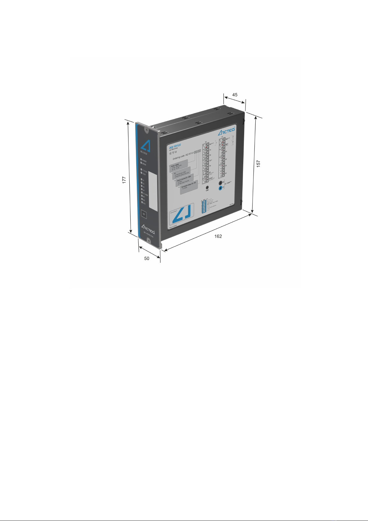
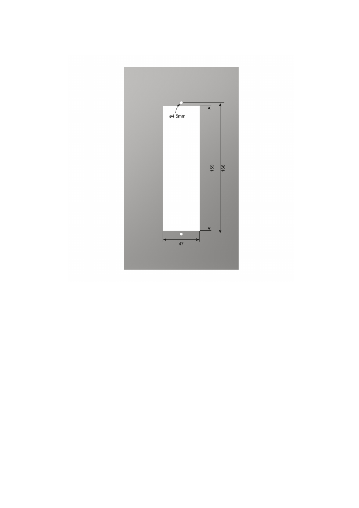
3.1. Dimensions and installation................................................................................................... 7
3.2. Wiring................................................................................................................................... 9
3.3. Unit features ....................................................................................................................... 10
3.4. SimpliZed block diagram ..................................................................................................... 11
4. Opera4. Operation and conZgtion and conZguraurationtion ............................................................................................................................................................................................................ 1313
4.1. LED indicator functions....................................................................................................... 13
4.2. LED operations guide ......................................................................................................... 13
4.3. Push-button (SET) .............................................................................................................. 14
4.3.1. System setup (auto-conZguration) ............................................................................ 14
4.3.2. Reset........................................................................................................................ 14
4.3.3. Input connection check ............................................................................................ 15
4.4. DIP switch settings ............................................................................................................. 15
4.4.1. Scheme selection ..................................................................................................... 16
4.4.2. Available logic schemes............................................................................................ 16
4.5. Non-volatile memory........................................................................................................... 18
5. Ar5. Arc sensorsc sensors.............................................................................................................................................................................................................................................................. 1919
5.1. Arc light Zber optic loop sensor AQ-06 ............................................................................... 19
5.2. Arc light Zber optic loop sensor AQ-07 ............................................................................... 19
5.3. Arc light Zber optic loop sensor AQ-08 ............................................................................... 20
5.4. Sensor—unit dependencies ................................................................................................ 21
5.5. Connecting sensors............................................................................................................ 21
6. S6. Syyststem self-superem self-supervisionvision.......................................................................................................................................................................................................................... 2222
7. Connections7. Connections............................................................................................................................................................................................................................................................ 2323
7.1. Outputs .............................................................................................................................. 26
7.1.1. Trip relays................................................................................................................. 26
7.1.2. inary outputs .......................................................................................................... 26
7.1.3. System failure relay................................................................................................... 27
7.2. Inputs ................................................................................................................................. 27
7.2.1. Arc sensor channels................................................................................................. 27
7.2.2. inary inputs ............................................................................................................ 27
7.3. Auxiliary voltage.................................................................................................................. 27
8. T8. Testingesting ............................................................................................................................................................................................................................................................................ 2828
8.1. Testing the light-only mode ................................................................................................. 28
8.2. Testing the light and current mode ...................................................................................... 28
8.3. Testing the C FP function................................................................................................... 29
8.4. Testing the unit operation time ............................................................................................ 29
8.5. Test plan example ............................................................................................................... 29
9. T9. Trroubleshoooubleshootingting.................................................................................................................................................................................................................................................. 3131
10. T10. Technicechnical daal datata.................................................................................................................................................................................................................................................. 3232
10.1. Protection......................................................................................................................... 32
10.2. Outputs ............................................................................................................................ 32
10.2.1. Trip relays............................................................................................................... 32
10.2.2. inary output(s) ...................................................................................................... 32
10.2.3. System failure relay................................................................................................. 32
10.3. inary inputs..................................................................................................................... 32
10.4. Auxiliary voltage................................................................................................................ 33
10.5. Sensors ............................................................................................................................ 33
10.6. Disturbance tests.............................................................................................................. 34
10.7. Voltage tests..................................................................................................................... 34
10.8. Mechanical tests............................................................................................................... 34
10.9. Environmental conditions .................................................................................................. 34
10.10. Casing and packaging .................................................................................................... 34
AAQQ-102L-102LVV
Version: 1.00
1 © Arcteq Relays Ltd

11. Or11. Ordering infdering informaormationtion .............................................................................................................................................................................................................................. 3535
12. Contact and r12. Contact and reeffererence infence informaormationtion...................................................................................................................................................................................... 3636
AAQQ-102L-102LVV
Version: 1.00
© Arcteq Relays Ltd 2

Disclaimer
Please read these instructions carefully before using the equipment or taking any other actions with
respect to the equipment. Only trained and qualiZed persons are allowed to perform installation,
operation, service or maintenance of the equipment. Such qualiZed persons have the responsibility to
take all appropriate measures, including e.g. use of authentication, encryption, anti-virus programs,
safe switching programs etc. necessary to ensure a safe and secure environment and usability of the
equipment. The warranty granted to the equipment remains in force only provided that the instructions
contained in this document have been strictly complied with.
Nothing contained in this document shall increase the liability or extend the warranty obligations of the
manufacturer Arcteq Relays Ltd. The manufacturer expressly disclaims any and all liability for any
damages and/or losses caused due to a failure to comply with the instructions contained herein or
caused by persons who do not fulZl the aforementioned requirements. Furthermore, the manufacturer
shall not be liable for possible errors in this document.
Please note that you must always comply with applicable local legislation and regulations. The
manufacturer gives no warranties that the content of this document is in all respects in line with local
laws and regulations and assumes no liability for such possible deviations.
You are advised to notify the manufacturer in case you become aware of any errors in this document or
of defects in the equipment.
The manufacturer reserves the right to update or amend this document at any time.
AAQQ-102L-102LVV
Version: 1.00
3 © Arcteq Relays Ltd

Copyright
Copyright © Arcteq Relays Ltd. 2020. All rights reserved.
AAQQ-102L-102LVV
Version: 1.00
© Arcteq Relays Ltd 4

1. Manual revision notes
RReevisionvision 1.001.00
Date September 2020
Changes - The Zrst revision of the manual.
AAQQ-102L-102LVV
Version: 1.00
5 © Arcteq Relays Ltd

2. Abbreviations
I – binary input
O – binary output
C – circuit breaker
C FP – circuit breaker failure protection
CT – current transformer
EPROM – erasable, programmable read-only memory
HSO – high-speed output
LED – light emitting diode
LV – low-voltage
MV – medium-voltage
NC – normally closed
NO – normally open
PC – printed circuit board
QD – quenching device
RF – radio frequency
Rx – receiver
SAS – standard arc scheme
SF – system failure
Tx – transceiver
μP - microprocessor
AAQQ-102L-102LVV
Version: 1.00
© Arcteq Relays Ltd 6

3. General
The AQ-102LV Zber optic loop sensor device is a sophisticated microprocessor-based arc flash
protection unit that includes complete self-supervision. The device is designed to minimize the damage
caused by an arcing fault (arc flash) by tripping the circuit breaker which supplies current to the fault.
The complete system self-supervision functionality of AQ-102LV provides the highest level of
dependability as it continuously monitors all internal system functions as well as all external
connections.
The AQ-102LV device is designed according to the latest protection relay standards and is therefore
suitable for installations in rough environments. These include utilities and power plants (both traditional
and renewable), various heavy industry applications (off-shore, marine, oil, gas, mining, steel, etc.) as
well as commercial and institutional electrical systems. While AQ-102LV is suitable for MV use, it is
designed for LV switchgears and for motor control center applications in both new and retroZtted
installations.
3.1. Dimensions and installation
AQ-102LV can be either door-mounted or panel-mounted in a standard 19 inch rack. The unit's
dimensions are as follows:
• Height: 177 mm (7.00")
• Width: 50 mm (1.97")
• Depth: 162 mm (6.38").
The Zgure below presents a side view of the device and gives the dimensions in more detail. Please
note that all values are given in millimeters.
AAQQ-102L-102LVV
Version: 1.00
7 © Arcteq Relays Ltd

Figure. 3.1. - 1. Dimensions of the device.
The image below presents the dimensions of the cut-out needed for mounting the unit on a panel.
AAQQ-102L-102LVV
Version: 1.00
© Arcteq Relays Ltd 8

Figure. 3.1. - 2. Cut-out for panel-mounting a unit.
3.2. Wiring
AAQQ-102L-102LVV
Version: 1.00
9 © Arcteq Relays Ltd

Figure. 3.2. - 3. Wiring diagram for AQ-102LV.
3.3. Unit features
AQ-102LV is a multipurpose arc flash protection unit and can be applied to a variety of applications. It
can be used on its own as a stand-alone unit, or it can be a part of a more complex arc protection
system through a binary bus.
The following list presents the main features of the unit:
• 92…265 V AC/DC auxiliary power supply oror 18…72 V DC auxiliary power supply (optional)
• three (3) Zber loop channels
• two (2) binary inputs with nominal operation voltage of 24 V DC
• three (3) normally open trip relay outputs
• one (1) normally open trip relay output oror one (1) normally closed trip relay output (electronic
lock-out)
• one (1) binary output (24 V DC)
• one (1) system failure output
• eleven (11) indication LEDs
• one (1) push-button.
AAQQ-102L-102LVV
Version: 1.00
© Arcteq Relays Ltd 10

Figure. 3.3. - 4. Arc protection unit AQ-102LV.
3.4. Simpli>ed block diagram
The Zgure below presents the main components of the AQ-102LV unit.
AAQQ-102L-102LVV
Version: 1.00
11 © Arcteq Relays Ltd

Figure. 3.4. - 5. SimpliZed block diagram of AQ-102LV.
AAQQ-102L-102LVV
Version: 1.00
© Arcteq Relays Ltd 12

4. Operation and con>guration
4.1. LED indicator functions
The AQ-102LV unit has eleven (11) indication LEDs. Apart from the "Power" and "Error" LEDs, the user
can write their own identiZcations for each of the remaining LEDs on the text insert located in the
transparent pocket next to the LEDs. The LEDs are on the unit's front panel to allow for a clear view
without a separate need to open doors.
When the unit is powered up, it performs an LED test. All LEDs are turned on for two seconds and then
turned off. Only the blue "Power" LED stays on.
When the unit operates normally, only the blue "Power" LED is lit.
The LEDs of inactive sensors are off. If an arc sensor is activated for longer than 1.5 ms, its
corresponding LED turns on. The activation function of the sensor LEDs is latched when the LED's light
is not blinking.
If there is a loose sensor wire or if the self-supervision function detects a conZguration mismatch (that
is, a new sensor has been attached but the auto-conZguration system setup has not been run), the
corresponding LED starts flashing and the "Error" LED activates.
The binary I/O LEDs indicate the status of the input and output lines. If any of the lines become active
for longer than 1.5 ms, the corresponding LED turns on (that is, they become latched). This also
happens when a trip situation occurs. The trip outputs are controlled with DIP switch settings. All
activation and trip indication LEDs are latched, even if the DIP switch settings are in the non-latched
mode.
All LED indications are stored in the non-volatile memory (EPROM) to help identify the necessary trip
information if auxiliary power is lost. When the unit is re-powered after a power supply loss, the front
panel shows the status of all LEDs.
You can clear the LEDs by pushing the SETSET button.
4.2. LED operations guide
The table below describes the function of each indicator LED in detail.
Table. 4.2. - 1. LED operations AQ-102LV.
LED
name
(color)
Off Steady
light Blinking Action if abnormal
POWER
(blue)
The auxiliary
power supply
is
disconnected.
The auxiliary
power
supply is
connected.
N/A Check the power supply.
ERROR
(red)
The system is
healthy.
A system
failure has
occured.
A conZguration mismatch has been
detected. Protection is partially
operational.
Verify the system condition (see the
"System self-supervision" and
"Troubleshooting" chapters).
T1–T4
(red)
Normal
status.
The trip relay
in
question has
activated.
N/A
Check what caused the trip, clear the fault
and reset the indicator LEDs with the push-
button.
AAQQ-102L-102LVV
Version: 1.00
13 © Arcteq Relays Ltd

LED
name
(color)
Off Steady
light Blinking Action if abnormal
S1–S3
(amber)
Normal
status.
The Zber
sensor
channel has
activated.
The Zber sensor has dropped off or
a system setup has not been
performed.
Check the sensor continuity or perform a
system setup (see the "System setup"
chapter); oror, check what activated the
sensor.
AQD
(amber)
Normal
status.
The AQD
channel has
been
activated.
The Zber connection to the
quenching system has dropped off
or a system setup has not been
performed.
Check the Zber connection and/or the
system conZguration.
I1– I2
(amber)
Normal
status.
The binary
input has
been
activated.
The binary input has a loose
connection. Check the binary input wiring.
O1
(amber)
Normal
status.
The binary
output has
been
activated.
N/A -
4.3. Push-button (SET)
The unit contains one push-button, SETSET, and it can be used for all operational functions. The push-
button is used for setting up the system (also known as auto-conZguration), for resetting the indicator
LEDs and the latched output relays, as well as for checking the input connection.
4.3.1. System setup (auto-con>guration)
After all sensors and binary lines have been connected, a system setup procedure (also known as
auto-conZguration) must be performed. The sequence is initialized by pressing the SETSET push-button for
two seconds. This causes the sensor and binary LEDs to start blinking. The unit scans these inputs to
see if they are connected; when an input is detected, the corresponding LED lights up to mark that a
connection was found. All inputs that are not connected continue to blink for three more seconds.
Then, all LEDs are turned off. Additionally, the DIP switch setting are stored in the non-volatile memory
during this sequence.
All sensor inputs remain operational even when they have not been auto-conZgured. System setup is
only used for self-supervision purposes.
Please note that to reconZgure a unit with fewer connections ( I/ O or sensors) than in the previously
memorized setup, one of the DIP switches must be moved back and forth once before the system
setup procedure is carried out. After this, you must wait one minute before you begin the new auto-
conZguration sequence.
You can reconZgure a unit with more connections at any time without the wait and without having to
move one of the DIP switches.
4.3.2. eset
All LED indications and latched trip relays can be reset by pressing the SETSET push-button for
one second.
Unless the button is pressed, the latched trip relays remain active until the auxiliary power is
disconnected. All LED indications also remain active even when the auxiliary power supply is
disconnected unless the button is pressed. Please refer to the "Non-volatile memory" chapter for more
information.
AAQQ-102L-102LVV
Version: 1.00
© Arcteq Relays Ltd 14

4.3.3. Input connection check
After the system setup (auto-conZguration) procedure is completed, you can verify the connectivity of
all sensors and binary input channels by pressing the SETSET push-button three (3) times within two
(2) seconds. The LEDs of the corresponding sensors and binary input channels start blinking while the
"Power" LED is already blinking. The LEDs blink as many times as there are connected sensors and
binary output channels from other units.
4.4. DIP switch settings
The DIP switches are used to conZgure the unit's tripping logic and other functionalities. The various
trip schemes can be programmed easily by selecting the appropriate DIP switch positions, which
allows for more flexibility when changing the settings depending on the application. Tripping can be
based on arc ligh only, or on both arc light and current thresholds, or on other tripping criteria (such as
undervoltage, etc.). Current threshold and other tripping criteria can also be applied to I1 to block
tripping caused by natural light sources. The C FP (circuit breaker failure protection) scheme can also
be enabled with the DIP switches. The DIP switch's pins 1…4 are used for selecting schemes, and
their numbering is based on binary arithmetic.
The DIP switches are located at the back of the unit for easy access. The Zgure below presents the DIP
switch numbering, and the table below that gives a detailed description of the settings.
Figure. 4.4. - 6. DIP switch diagram.
Table. 4.4. - 2. DIP switch settings.
Pin
number
(name)
Function selection ON (left position) OFF (right position)
8
(L> oror L>
+ I>)
The tripping criterion for
the S2, S3, S4 (sensor)
and S5 (Zber) channels.
Tripping on light only (L>).
Tripping on light and overcurrent (L> + I>),
both of which are required to occur
simultaneously to trigger tripping.
7
(S1: L>
oror L> +
I>)
The tripping criterion for
the S1 sensor channel. Tripping on light only (L>).
Tripping on light and overcurrent (L> + I>),
both of which are required to occur
simultaneously to trigger tripping.
6
(Latch
oror Non-
latch)
Latching or non-latching
for the T1 and T2 trip
relays.
T1 and T2 operate as latched. T1 and T2 operate as non-latched.
AAQQ-102L-102LVV
Version: 1.00
15 © Arcteq Relays Ltd

Pin
number
(name)
Function selection ON (left position) OFF (right position)
5
( locking
function)
Selects between the
blocking function and the
current signal.
The blocking function is selected. All
trip signals (T1…T4) and the quencher
control (AQD) are blocked.
The current signal is selected.
4
(scheme
select)
Scheme selection. Please refer to the "Scheme selection"
and "Application examples" chapters.
Please refer to the "Scheme selection" and
"Application examples" chapters.
3
(scheme
select)
Scheme selection. Please refer to the "Scheme selection"
and "Application examples" chapters.
Please refer to the "Scheme selection" and
"Application examples" chapters.
2
(scheme
select)
Scheme selection. Please refer to the "Scheme selection"
and "Application examples" chapters.
Please refer to the "Scheme selection" and
"Application examples" chapters.
1
(scheme
select)
Scheme selection. Please refer to the "Scheme selection"
and "Application examples" chapters.
Please refer to the "Scheme selection" and
"Application examples" chapters.
4.4.1. Scheme selection
This chapter describes the schemes that are available to this unit. The schemes are conZgured using
the DIP switches numbered 1…4 ("Scheme selection").
4.4.2. Available logic schemes
The schemes described below are the most important ones for this unit. However, additional schemes
are also available; please contact your nearest Arcteq representative for more information on
those schemes.
SS:0
1) If the blocking function (SW1: 5) is ON, the activation of I2 block all trip output signals.
2) If the blocking function (SW1: 5) is OFF, the binary input I2 can be used to receive an external
current signal. The tripping criterion can be selected to be light only (L>) or both light and current (L> +
I>).
AAQQ-102L-102LVV
Version: 1.00
© Arcteq Relays Ltd 16

SS:1
1) If the blocking function (SW1: 5) is ON, the activation of I1 block all trip output signals.
2) If the blocking function (SW1: 5) is OFF, the binary input I1 can be used to receive an external
current signal. The tripping criterion can be selected to be light only (L>) or both light and current (L> +
I>).
3) Only available when the unit's conZguration includes the light-only setting (i.e. when "L>" has been
selected for the DIP switch SW1: 6).
SS:2
1) If the blocking function (SW1: 5) is ON, the activation of I2 block all trip output signals.
2) If the blocking function (SW1: 5) is OFF, the binary input I2 can be used to receive an external
current signal. The tripping criterion can be selected to be light only (L>) or both light and current (L> +
I>).
NONOTE!TE!
In this scheme, the binary input I1 is used as the input for the device reset.
AAQQ-102L-102LVV
Version: 1.00
17 © Arcteq Relays Ltd

SS:3
1) If the blocking function (SW1: 5) is ON, the activation of I2 block all trip output signals.
2) If the blocking function (SW1: 5) is OFF, the binary input I2 can be used to receive an external
current signal. The tripping criterion can be selected to be light only (L>) or both light and current (L> +
I>).
SS:4
1) If the blocking function (SW1: 5) is ON, the activation of I1 block all trip output signals.
2) If the blocking function (SW1: 5) is OFF, the binary input I1 can be used to receive an external
current signal. The tripping criterion can be selected to be light only (L>) or both light and current (L> +
I>).
3) Only available when the unit's conZguration includes the light-only setting (i.e. when "L>" has been
selected for the DIP switch SW1: 6).
4.5. Non-volatile memory
All critical system data (such as DIP switch settings and the system setup Zle) are stored in the non-
volatile memory (EPROM) to ensure accurate operation and full self-supervision even if auxiliary power
is lost temporarily.
Additionally, all LED indications are stored in the non-volatile memory to provide a quick recovery of the
system status indication. This feature is especially important if tripping causes the unit to lose its
auxiliary power.
The non-volatile memory does not require a power supply to maintain the information and it retains the
settings and the indications permanently without power.
AAQQ-102L-102LVV
Version: 1.00
© Arcteq Relays Ltd 18

5. Arc sensors
The AQ-100 series provides different types of arc sensors to be used with different units and different
switchgear types according to speciZc application requirements. There are two types of sensors: arc
light point sensors and arc light Zber optic loop sensors.
Arc light point sensors are typically installed in metal-clad compartments, and they provide a quick and
accurate location of the faulted area. Arc light Zber loop sensors typically cover a wider protected area
with one Zber, when there is no need to pinpoint the exact location for a fault.
5.1. Arc light >ber optic loop sensor AQ-06
AQ-06 is an arc light Zber optic loop sensor, which is a plastic Zber optic cable. Fiber sensors are
distributed through the protected switchgear cells. The Zxed light intensity threshold of an AQ-06
sensor is 8,000 lux. The sensor does not require further settings by the user. The sensor's detection
radius is 360 degrees.
AQ-06 sensors can be ordered in pre-manufactured lengths of 3…40 meters (3 m, 5 m, 10 m, 15 m,
20 m, 25 m, 30 m, 35 m, 40 m). It is not recommended to cut or splice the cable on-site. However, if
cutting or splicing is necessary due to the cable breaking, please contact your nearest Arcteq
representative for instructions.
When requested, the ends of an AQ-06 cable can be covered with black rubber to avoid light detection
outside the protected zone (see the Zgure below). The covered area can be as large or small as
necessary. For more information, please consult your nearest Arcteq representative.
Figure. 5.1. - 7. AQ-06 sensor with covered ends.
5.2. Arc light >ber optic loop sensor AQ-07
AQ-07 is an arc light Zber optic loop sensor, which is a robust Zber optic cable with a practically
unlimited bending radius. The sensor contains hundreds of glass Zber drains covered by a plastic tube,
thus making it extremely strong and durable. Fiber sensors are distributed through the protected
switchgear cells.
AQ-07 sensors can be ordered in pre-manufactured lengths of 3…50 meters (3 m, 5 m, 10 m, 15 m,
20 m, 25 m, 30 m, 35 m, 40 m, 45 m, 50 m). It is not recommended to cut or splice the cable on-site.
However, if cutting or splicing is necessary due to the cable breaking, please contact your nearest
Arcteq representative for instructions.
AAQQ-102L-102LVV
Version: 1.00
19 © Arcteq Relays Ltd
Other manuals for AQ-102LV
1
Table of contents
Other Arcteq Protection Device manuals

Arcteq
Arcteq AQ F3 0 Series User manual

Arcteq
Arcteq AQ-101S User manual

Arcteq
Arcteq AQ-M210 User manual

Arcteq
Arcteq AQ F205 User manual

Arcteq
Arcteq AQ-103LV User manual

Arcteq
Arcteq AQ 110 Series User manual

Arcteq
Arcteq AQ-101S User manual

Arcteq
Arcteq AQ-R215 User manual

Arcteq
Arcteq AQ-M257 User manual

Arcteq
Arcteq AQ-101 User manual

Arcteq
Arcteq AQ-T256 User manual

Arcteq
Arcteq AQ-T216 User manual

Arcteq
Arcteq AQ-101 User manual

Arcteq
Arcteq AQ-S254 User manual

Arcteq
Arcteq AQ 102 User manual

Arcteq
Arcteq AQ-F215 User manual

Arcteq
Arcteq AQ 200 Series User manual

Arcteq
Arcteq AQ-G3 7 Series User manual

Arcteq
Arcteq AQ-T256 User manual

Arcteq
Arcteq AQ-M257 User manual