Filtertechnik PC9001 User manual

Table of contents
Specifications on page 3
General information on page 4
Installation on page 6
User interface and navigation on page 11
Operation on page 12
Data management on page 14
Maintenance on page 17
Troubleshooting on page 18
Replacement parts and accessories on page 20
Specifications
Specifications are subject to change without notice.
Specification Details
Dimensions (L x W x H) 8.9 x 10.7 x 8.9 cm (3.5 x 4.2 x 3.5 in.)
Enclosure IP 66
Fitting connections SAE -4; SAE -8
Power requirements 9 to 33 VDC, 150 mA
Storage temperature –40 to 85 °C (–40 to 185 °F)
Operating temperature –10 to 60 °C (–14 to 140 °F)
Altitude limit 2000 m (6562 ft)
Overvoltage category I
Pollution degree 4
Protection class III
Light source Laser diode, Class I
Particle size/channel 4, 6, 14 and 21 μm (ISO MTD)
Storage/operating humidity 97% relative humidity, non-condensing
Fluid compatibility Hydraulic and lubrication oils, mineral, synthetic (phosphate ester compatible)
Fluid viscosity 2 to 424 cSt1
Reports ISO 4406, NAS and SAE cleanliness codes
Wetted materials Brass, aluminum (anodized), steel, stainless steel, sapphire, Aflas®
Performance verification Optional validation certificate available (ISO MTD at 2.8 mg/L concentration)
Reproducibility ±0.5 ISO code (minimum concentration ISO MTD 2.8 mg/L, maximum ISO code
is 29)
Weight 746 grams (2 lb)
Serial interface RS232 and RS485, 9600 Baud, 8 data bits, no parity, 1 stop bit
Communication protocol MODBUS RTU
Flow rate for 3&-31, 3&-61 50 to 500 mL/min (0.01 to 0.1 gal/min)
Flow rate for 3&-21, 3&-51 3.8 to 45.4 L/min (1 to 12 gal/min)
Sample pressure PC9001-71, PC9001-81: 12 to 100 psi
Sample temperature 0 to 60 °C (32 to 140 °F)
Sample pressure 20 to 7250 psi
English 3

Specification Details
Warranty 1 year
Certifications CE and FDA Accession No. 9320350-008
1Viscosities tested at ambient temperature: 25 °C ±2 degrees; 77 °F ±2 degrees
General information
In no event will the manufacturer be liable for direct, indirect, special, incidental or consequential
damages resulting from any defect or omission in this manual. The manufacturer reserves the right to
make changes in this manual and the products it describes at any time, without notice or obligation.
Revised editions are found on the manufacturer’s website.
Safety information
N O T I C E
The manufacturer is not responsible for any damages due to misapplication or misuse of this product including,
without limitation, direct, incidental and consequential damages, and disclaims such damages to the full extent
permitted under applicable law. The user is solely responsible to identify critical application risks and install
appropriate mechanisms to protect processes during a possible equipment malfunction.
Please read this entire manual before unpacking, setting up or operating this equipment. Pay
attention to all danger and caution statements. Failure to do so could result in serious injury to the
operator or damage to the equipment.
Make sure that the protection provided by this equipment is not impaired. Do not use or install this
equipment in any manner other than that specified in this manual.
Use of hazard information
D A N G E R
Indicates a potentially or imminently hazardous situation which, if not avoided, will result in death or serious injury.
WARNING
Indicates a potentially or imminently hazardous situation which, if not avoided, could result in death or serious
injury.
CAUTION
Indicates a potentially hazardous situation that may result in minor or moderate injury.
N O T I C E
Indicates a situation which, if not avoided, may cause damage to the instrument. Information that requires special
emphasis.
Precautionary labels
This is the safety alert symbol. Obey all safety messages that follow this symbol to avoid potential
injury. If on the instrument, refer to the instruction manual for operation or safety information.
This symbol indicates that a risk of electrical shock and/or electrocution exists.
4 English

This symbol indicates a laser device is used in the equipment.
Electrical equipment marked with this symbol may not be disposed of in European public disposal
systems after 12 August of 2005. In conformity with European local and national regulations (EU
Directive 2002/98/EC), European electrical equipment users must now return old or end-of-life
equipment to the Producer for disposal at no charge to the user.
Note: For return for recycling, please contact the equipment producer or supplier for instructions on how to return end-
of-life equipment, producer-supplied electrical accessories, and all auxiliary items for proper disposal.
Certification
Canadian Radio Interference-Causing Equipment Regulation, IECS-003, Class A:
Supporting test records reside with the manufacturer.
This Class A digital apparatus meets all requirements of the Canadian Interference-Causing
Equipment Regulations.
Cet appareil numèrique de la classe A respecte toutes les exigences du Rëglement sur le matériel
brouilleur du Canada.
FCC Part 15, Class "A" Limits
Supporting test records reside with the manufacturer. The device complies with Part 15 of the FCC
Rules. Operation is subject to the following conditions:
1. The equipment may not cause harmful interference.
2. The equipment must accept any interference received, including interference that may cause
undesired operation.
Changes or modifications to this equipment not expressly approved by the party responsible for
compliance could void the user's authority to operate the equipment. This equipment has been tested
and found to comply with the limits for a Class A digital device, pursuant to Part 15 of the FCC rules.
These limits are designed to provide reasonable protection against harmful interference when the
equipment is operated in a commercial environment. This equipment generates, uses and can
radiate radio frequency energy and, if not installed and used in accordance with the instruction
manual, may cause harmful interference to radio communications. Operation of this equipment in a
residential area is likely to cause harmful interference, in which case the user will be required to
correct the interference at their expense. The following techniques can be used to reduce
interference problems:
1. Disconnect the equipment from its power source to verify that it is or is not the source of the
interference.
2. If the equipment is connected to the same outlet as the device experiencing interference, connect
the equipment to a different outlet.
3. Move the equipment away from the device receiving the interference.
4. Reposition the receiving antenna for the device receiving the interference.
5. Try combinations of the above.
Class 1 laser product
This instrument is classified as a Class 1 laser product. This product complies with IEC/EN
60825-1:2007 and 21 CFR 1040.10 except for deviations pursuant to Laser Notice No. 50, dated
June 24, 2007.
US FDA Laser Accession number 9320350-008. This product contains a 780 nm 5 mW class 3B
laser that is not user-serviceable.
Product overview
This instrument is used to validate the cleanliness level and particulate count in oil. The data can be
viewed on the instrument display or a computer. The software shows the current data or previously
English 5


Figure 5 Cable connections
1 9 to 33 VDC 2 Alarm driver
Table 1 Male connector wires—DB15 cable
Pin number Color Function
1 White Power input (9 to 33 VDC)
2 Brown Power ground (return)
3 Green Alarm driver
4 Yellow —
5 Gray RS232-RXD (receive data)
6 Pink RS232-TXD (transmit data)
7 Blue —
8 Red —
9 Orange RS232-GND (signal return)
10 Tan RS485-A (signal A of differential serial driver pair)
11 Black RS485-B (signal B of differential serial driver pair)
12 Violet RS485-SGND (shield ground connection)
Table 2 Female connector wires—DB15 cable
Pin number Color Function
1 White Power input (9 to 33 VDC)
2 Brown Power ground (return)
3 Green Alarm driver
4 Yellow —
5 Gray RS232-RXD (receive data)
English 9
Table 2 Female connector wires—DB15 cable (continued)
Pin number Color Function
6 Pink RS232-TXD (transmit data)
7 Blue —
8 Red —
9 Orange RS232-GND (signal return)
10 Tan RS485-A (signal A of differential serial driver pair)
11 Black RS485-B (signal B of differential serial driver pair)
12 Violet RS485-SGND (shield ground connection)
13 — —
14 — —
15 — —
Table 3 Male connector wires—DB15 to DB9 cable
Pin number Color Function
1 Red1 Power input (9 to 33 VDC)
2 Black1 Power ground (return)
3 White1 Alarm driver
4 — —
5 Red2 RS232-RXD (receive data)
6 Black2 RS232-TXD (transmit data)
7 — —
8 — —
9 White2 RS232-GND (signal return)
10 — —
11 — —
12 — —
13 — —
14 — —
15 — —
Table 4 Female connector wires—DB15 to DB9 cable
Pin number Color Function
1 — —
2 Black2 RS232-TXD (transmit data)
3 Red2 RS232-RXD (receive data)
4 — —
5 White2 RS232-GND (signal return)
10 English


Table 6 Keypad functions
Indicator lights and keys Description
ISO indicator light Shows the last ISO code on any one of four sizes.
Code limit indicator lights Shows the ISO, SAE and NAS code limits.
Alarm indicator light Flashes along with the selected size indicator light when a cleanliness code alarm
limit is exceeded.
R SCROLL key Moves down through the four sizes only when ISO, NAS or SAE is selected. Shows
any system or cleanliness code alarm. Flashes when the first key is pushed.
L SCROLL key Moves down through the options on the left side of the display. Shows any system or
cleanliness code alarm. Flashes when the first key is pushed.
STATUS indicator light Shows a numerical system status code. Flashes when there is a system alarm.
T °C indicator light Shows the system temperature from the last completed sample (XX.X).
SAE indicator light Shows the last SAE code on any one of the four sizes.
NAS indicator light Shows the last NAS code on any one of the two differential groups (indicator lights
6–14 or 14–21).
Operation
Configure the instrument
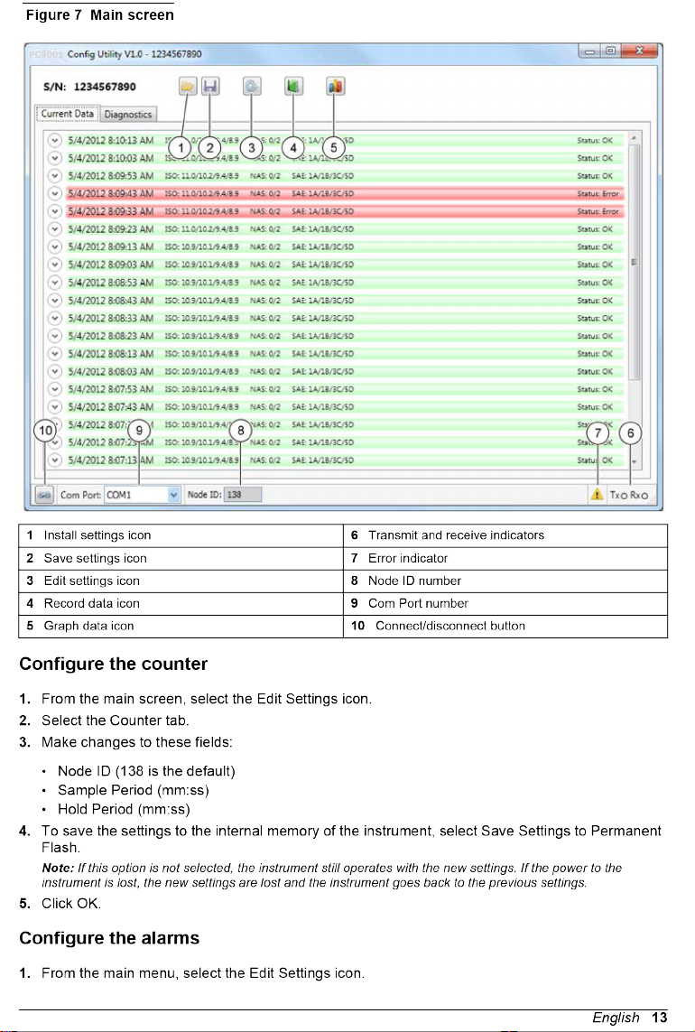
1. Open the PC9001 Configuration Utility. A window opens (Figure 7).
2. Select the communication (COM) port on the computer that is connected to the counter.
3. Change the Node ID setting to the Node ID of the instrument. The default Node ID setting for new
instruments is 138. Display versions of the instrument show the Node ID for the first three
seconds after power up.
4. Click the connect/disconnect button to connect to the counter.
12 English
PC9001

2. Select the Alarms tab.
3. Make changes to these fields:
• Standard (ISO, NAS or SAE)
• Alarm Direction (Clean to Dirty or Dirty to Clean)
• Code Limits (4, 6, 14 or 21 µm) If NAS is selected as the Standard, only the code limits for 6–
14 µm and 14–21 µm will be available.
4. To open the contact when an alarm occurs, select Open Contact on Alarm.
5. To close the contact when an alarm occurs, do not select Open Contact on Alarm.
6. To save the settings to the instrument internal memory, select Save Settings to Permanent Flash.
Note: If this option is not selected, the instrument still operates with the new settings. If the power to the
instrument is lost, the new settings are lost and the instrument goes back to the previous settings.
7. Click OK.
Configure the general settings
1. From the main menu, select the Edit Settings icon.
2. Select the General tab.
3. Make changes to these fields.
• Display ISO Codes (All Codes or Highest Code)
• Display NAS Codes (All Codes or Highest Code)
• Display SAE Codes (All Codes or Highest Code)
4. To calculate average counts, select Calculate Average Counts and adjust the number of samples.
5. To change the output folder, click the button next to the Log File Output Folder field and select
the desired folder. As an option, move a copy of the output folder into the text box.
6. Click OK.
Data management
Load the settings
1. From the main menu, select the Load Settings icon.
2. Enter a location and a file name.
3. Click Open.
Save the settings to a computer
1. From the main menu, select the Save Settings icon.
2. Enter a location and a file name.
3. Click Save.
To see the current data
1. From the main menu, select the Current Data tab.
2. Click a down arrow (next to each record) to see the particle count data, average particle count
data and temperature.
3. To see the errors for an individual data record, move the cursor over the Status text that is
located on the right side of the screen. A window opens and shows the error code and a text
description of the errors.
14 English


Clean the instrument
WARNING
Chemical exposure hazard. Obey laboratory safety procedures and wear all of the personal protective
equipment appropriate to the chemicals that are handled. Refer to the current material safety data
sheets (MSDS) for safety protocols.
Clean the exterior of the instrument with a moist cloth and a mild soap solution.
Replace the hoses
WARNING
Personal injury hazard. Enclosed systems contain high pressure. Qualified personnel must remove
pressure from the system before the instrument can be installed or removed.
Visually inspect the sample hoses for wear or deterioration at least every 6 months, more frequently
if conditions are harsh. If the hoses need to be replaced, do these steps.
1. Remove the pressure from the system.
2. Remove the power from the instrument.
3. Remove the hoses.
4. Use replacement hoses with adequate pressure ratings.
Calibration
The instrument cannot be calibrated by the user. Contact the manufacturer for instrument calibration.
Troubleshooting
Error indicator
When an error occurs, an exclamation point appears on the main menu of the PC9001 Configuration
Utility.
1. Double-click on the exclamation point. A window opens (Figure 11).
2. Click on a current error. Details are shown in the lower section of the window.
3. To remove the list of errors in the window, click Clear List. This removes the error indicator from
the main screen.
18 English


Table 7 Alarm codes (continued)
Hexadecimal code Description
100 There is a 4 µm code alarm.
200 There is a 6 µm code alarm.
400 There is a 14 µm code alarm.
800 There is a 21 µm code alarm.
Replacement parts and accessories
Note: Product and Article numbers may vary for some selling regions. Contact the appropriate distributor or refer to
the company website for contact information.
There are no replacement parts for this instrument.
Table 8 Accessories
Description Quantity Item no.
Cable, external interface DB9 1 2089490
Cable, DB15 to DB9 1 2089491
Power supply 1 230-300-0001
Utility software 1 2089264
Disposal:
The unit might become contaminated in the course of use. Dispose of the product in accordance to
local and regional regulations.
Appendix
Particle count and other codes
Filtertechnik codes
Table 9 shows the Filtertechnik 4406 codes that are based on ISO 4406.
To change Filtertechnik codes to ISO codes, delete all of the digits to the right of the decimal point. Do not
change the value either up or down. For example, a Filtertechnik code readout of 7.2 is equivalent to an ISO
code of 7. A Filtertechnik code of 7.8 is also equivalent to an ISO code of 7.
Set the sample time to get a statistically significant number of particles in the sample. For expected
ISO code ranges that are greater than or equal to 12 A, a 1-minute sample time should be sufficient.
For code ranges less than 12 A, multiply the sample time by 2 for each ISO code level. For example,
use a 2-minute sample time at ISO code 11.
Table 9 Filtertechnik 4406 codes and maximum particle counts
Code Counts/mL Code Counts/mL Code Counts/mL Code Counts/mL Code Counts/mL
5 0.16 8 1.3 11 10 14 80 17 640
5.1 0.176 8.1 1.42 11.1 11 14.1 88 17.1 706
5.2 0.192 8.2 1.54 11.2 12 14.2 96 17.2 772
5.3 0.208 8.3 1.66 11.3 13 14.3 104 17.3 838
5.4 0.224 8.4 1.78 11.4 14 14.4 112 17.4 904
5.5 0.24 8.5 1.9 11.5 15 14.5 120 17.5 970
20 English

Table 9 Filtertechnik 4406 codes and maximum particle counts (continued)
Code Counts/mL Code Counts/mL Code Counts/mL Code Counts/mL Code Counts/mL
5.6 0.256 8.6 2.02 11.6 16 14.6 128 17.6 1036
5.7 0.272 8.7 2.14 11.7 17 14.7 136 17.7 1102
5.8 0.288 8.8 2.26 11.8 18 14.8 144 17.8 1168
5.9 0.304 8.9 2.38 11.9 19 14.9 152 17.9 1234
6 0.32 9 2.5 12 20 15 160 18 1300
6.1 0.352 9.1 2.75 12.1 22 15.1 176 18.1 1420
6.2 0.384 9.2 3 12.2 24 15.2 192 18.2 1540
6.3 0.416 9.3 3.25 12.3 26 15.3 208 18.3 1660
6.4 0.448 9.4 3.5 12.4 28 15.4 224 18.4 1780
6.5 0.48 9.5 3.75 12.5 30 15.5 240 18.5 1900
6.6 0.512 9.6 4 12.6 32 15.6 256 18.6 2020
6.7 0.544 9.7 4.25 12.7 34 15.7 272 18.7 2140
6.8 0.576 9.8 4.5 12.8 36 15.8 288 18.8 2260
6.9 0.608 9.9 4.75 12.9 38 15.9 304 18.9 2380
7 0.64 10 5 13 40 16 320 19 2500
7.1 0.706 10.1 5.5 13.1 44 16.1 352 19.1 2750
7.2 0.772 10.2 6 13.2 48 16.2 384 19.2 3000
7.3 0.838 10.3 6.5 13.3 52 16.3 416 19.3 3250
7.4 0.904 10.4 7 13.4 56 16.4 448 19.4 3500
7.5 0.97 10.5 7.5 13.5 60 16.5 480 19.5 3750
7.6 1.036 10.6 8 13.6 64 16.6 512 19.6 4000
7.7 1.102 10.7 8.5 13.7 68 16.7 544 19.7 4250
7.8 1.168 10.8 9 13.8 72 16.8 576 19.8 4500
7.9 1.234 10.9 9.5 13.9 76 16.9 608 19.9 4750
20 5000 22 20000 24 80000 26 320000 28 1300000
20.1 5500 22.1 22000 24.1 88000 26.1 352000 28.1 1420000
20.2 6000 22.2 24000 24.2 96000 26.2 384000 28.2 1540000
20.3 6500 22.3 26000 24.3 104000 26.3 416000 28.3 1660000
20.4 7000 22.4 28000 24.4 112000 26.4 448000 28.4 1780000
20.5 7500 22.5 30000 24.5 120000 26.5 480000 28.5 1900000
20.6 8000 22.6 32000 24.6 128000 26.6 512000 28.6 2020000
20.7 8500 22.7 34000 24.7 136000 26.7 544000 28.7 2140000
20.8 9000 22.8 36000 24.8 144000 26.8 576000 28.8 2260000
20.9 9500 22.9 38000 24.9 152000 26.9 608000 28.9 2380000
21 10000 23 40000 25 160000 27 640000 > 29.0 2500000
English 21
This manual suits for next models
6
Table of contents
Popular Cash Counter manuals by other brands

Royal Sovereign
Royal Sovereign RBC-1003 owner's manual

Talaris
Talaris Nvision quick start guide

Omron
Omron H7BX - instruction manual

Nautilus Hyosung
Nautilus Hyosung MONiMAX8800 installation manual

DEUTA Controls
DEUTA Controls enocean AL-436-00-921 manual

CTcoin
CTcoin Dolphin User's manual and operation instructions


