Pendulum CNT-66 User manual

CNT-66
Programmable Timer/Counter
Users Manual
I

II
4031 600 66001
Rev. 01 (September 2000)
This manual, in whole or in part, may not be copied without permission.
All product name are trademarks of their respective companies.
© 2000 Pendulum Instruments AB
All rights reserved. Printed in Sweden.

Table of Contents
EC DECLARATION OF CONFORMITY ........ IV
1 Safety Instructions
Safety ............................. 1-2
Introduction ............................. 1-2
2 Product Presentation
General ................................ 2-2
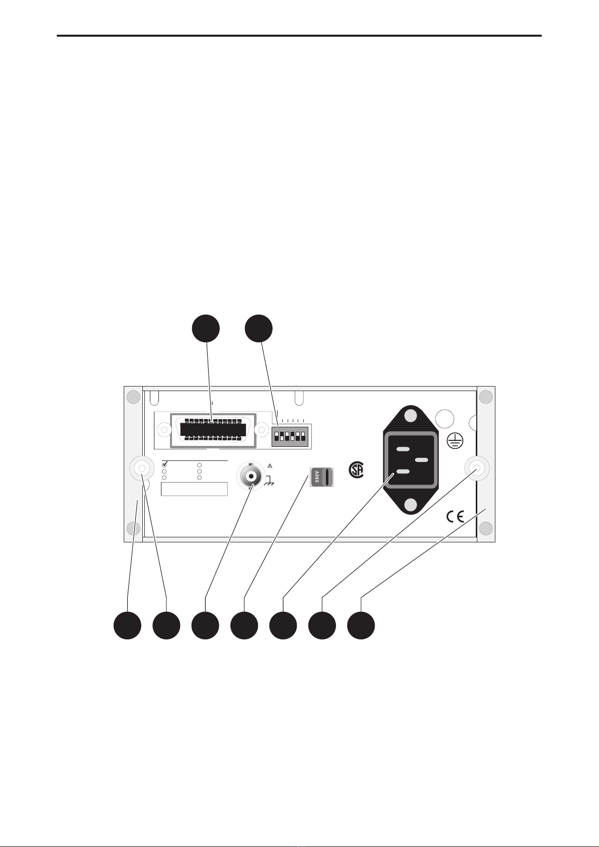
Rear View .............................. 2-2
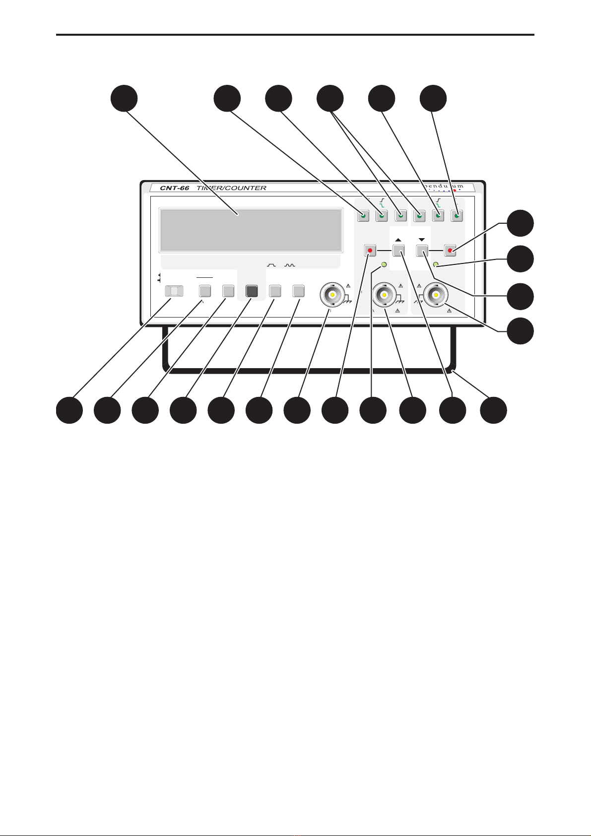
Front View .............................. 2-3
3 Installation
Unpacking .............................. 3-2
Voltage Range Selection................... 3-2
Grounding .............................. 3-3
Connecting External Reference ............. 3-3
Installing the Rack Mount Adapter ........... 3-3
4 Operating Instructions
Using the Timer/Counter ................... 4-2
Error Codes............................ 4-14
5 GPIB-interface Operation
Introduction ............................. 5-2
What can I do using the Bus? ............... 5-2
Connecting the Controller .................. 5-3
Giving the Counter an Address .............. 5-3
Checking the Communication ............... 5-3
Two Ways of Programming................. 5-4
Syntax ................................. 5-4
Selecting Output Separator................. 5-5
How to Select Function .................... 5-5
Selecting Measuring-Time.................. 5-6
Selecting Input settings .................... 5-6
Totalize Start/Stop........................ 5-7
Free-Run/Triggered....................... 5-7
Service Request ......................... 5-8
Status Byte ............................. 5-8
Output Mode ........................... 5-10
Bus Learn ............................. 5-12
Programming Data Out ................... 5-12
What Happens When I Switch to Local?...... 5-12
Summary of Bus Commands .............. 5-13
Programming Examples .................. 5-14
6 Performance Check
Performance Check....................... 6-2
7 Calibration and Adjustment
Calibration .............................. 7-2
Timebase References ..................... 7-3
8 Specifications
Measuring Functions...................... 8-2
Input-A and Input-B ....................... 8-3
Input C ................................ 8-3
External Reference Input D .................. 8-3
Auxiliary Functions ....................... 8-4
Definitions .............................. 8-4
General Specifications .................... 8-5
Environmental Data....................... 8-6
Mechanical Data ......................... 8-6
Optional Accessories...................... 8-6
Ordering Information ...................... 8-7
9 Appendix
Checking the Sensitivity of Counters.......... 9-2
10 Service
Sales and Service office................ II
GUARANTEE STATEMENT ................. III
11 Index
Index ............................... II
III

IV
EC DECLARATION OF CONFORMITY
Number: 4031 100 63700A41
The undersigned, representing the following manufacturer:
Manufacturer:
Pendulum Instruments AB
Sorterargatan 26, Box 541
SE-162 15 Vällingby, Sweden
Representative: Jan Herwe
Function: Quality Manager
herewith declare that the product:
Product Identification:
Product: Timer/Counter
Brand: Pendulum
Model: CNT-66
Version: All models
is in conformance with the EC Directive 89/336/EEC based on test results using harmonized standards in accordance with
Article 10(1) of the directive and the directive LVD-73/23/EEC.
Test report no: Title
Safety release certificate March 18, 1996
SEMKO EMC test report 953210I.3
CEM-Consult AB: CC-EMC/88-1044
Harmonized standards used:
Safety: EN 61010-1 (1990) + A1 (1992) + A2 (1995) CAT II
EMC: EN 55011 (1991) Group 1, Class B
EN 50082-1 (1992)
Place: Vällingby Date: 2000-05-29
This Conformity is indicated by the symbol , i.e. “Conformité européenne”.

Chapter 1
Safety Instructions

Safety
Introduction
Read this page carefully before you install and use the
CNT-66 Timer/Counter.
This Timer/Counter has been designed and tested in accor-
dance with EN 61010-1 and has been supplied in a safe
condition. The user of this instrument must have the re-
quired knowledge of CNT-66. This knowledge can be
gained by thoroughly studying this manual.
Safety Precautions
Use generally-accepted safety procedures, in addition to the
safety precautions stated in this manual, to ensure personal
safety and safe operation of the Timer/Counter.
Caution and Warning Statements
You will find specific warning and caution statements, where
necessary throughout the manual. Do not carry out repairs
or adjustments to the Timer/Counter without reading the
Service Manual, which contains the relevant warnings for
such activities.
CAUTION: Indicates where incorrect operating pro-
cedures can cause damage to, or
destruction of, equipment or other property.
WARNING: Indicates a potential danger that re-
quires correct procedures or practices in
order to prevent personal injury.
Symbols
Indicates where the protective ground lead is
connected inside the instrument. Never un-
screw or loosen this screw.
Signal Ground symbol. This symbol indicates
that the signal ground of the connectors are in-
ternally connected to the other connectors with
the same symbol, and to parts that are easily
accessible for the user.
Indicates that the operator should consult
the manual.
Such symbols are printed near the input connectors. This
symbol on the instrument should encourage the user to use
the correct procedure for common instrument ground, and
maximum input voltages, as described in the Installation
and Specification chapters.
If in Doubt About Safety
Whenever you suspect that it is unsafe to use the instru-
ment, you must make it inoperative, clearly mark it to pre-
vent its further operation, and inform the Pendulum servic-
ing department.
E.g.The instrument is likely to be unsafe if it is visibly dam-
aged.
Safety Instructions
1-2 Introduction

Chapter 2
Product Presentation

General
The CNT-66 is a compact, high resolution, reciprocal
Timer/Counter which performs many functions. A number of
options are available i.e. HF-input, GPIB-interface and high
stability oscillator.
A rack-mount kit and a carrying case are also available as
accessories.
Rear View
S) Rear feet.
T) Screws for removing the cover.
U) External-reference-input, BNC connector.
V) Voltage-range selector.
W) Power-inlet socket.
X) GPIB interface-connector (optional).
Y) GPIB address-selector ( option).
Product Presentation
2-2 General
M AINS TRANSFORM ER
INCLUDED OPTIONS
OPTION 08
OPTION 07
OPTION 04
ADDRESS
10M H z 0.5-15V rm s
IE E E 4 8 8 IN T E R F A C E
EXT REF INPUT
OPTION
TALK O N LY
16
LR 39484
VOLTAGE
SELECTOR
OFF
8421
ON DC1, DT1
E2
S R 1 , R L 1
S H 1 , A H 1
FUNCTIONS:
SUPPO RTED
T 5 , L 4
T H E R M A L F U S E IN
S
T U
V
W
T
S
X
Y
OPTION
OPTION
Figure 2-1 Rear View

Front View
A) Power switch.
B) Reset button, doubles as Local button if the
Timer/Counter is equipped with an GPIB interface.
Starts and stops counting if the TOT A MAN func-
tion is selected.
C) Measuring-time selector-button. *
D) Function-selector button. *
E) Display-hold button. Freezes the display.
F) COM B via A button connects the signal on input A
to input B. The Input-A attenuator and AC/DC
switch affect both inputs.
G) Input-C BNC-connector (optional).
H) Input-A BNC-connector.
I) Set value button, depress to set sensitivity (AC) or
trigger level (DC).
J) Auto level, starts automatic trigger level setting. If
‘Set Value’ is selected, this button is used to in-
crease the value.
K) Read level, displays trigger levels. If ‘Set Value’ is
depressed, this button is used to decrease the
value.
L) Input-B BNC-connector.
M) Trigger indicators.
N) Attenuator buttons.
O) Slope selection buttons.
P) DC or AC coupling selection buttons.
Q) Large LCD-display.
R) Tilting support.
* The selected function is indicated on the display. A
short press on the button moves the cursor one
step to the right. A long press makes the cursor
scroll.
Product Presentation
2-3 Front View
SET A SET B
35pF
ATTx1
FREQ
STANDBY
ON
A
HOLD
DISPL
TO T A
COMMON
P E R IO D T IM ERATIO
A/B
START/STO P
TO TALIZE A
LO C A L
RESET
AA-B
FU NC TIO N
B
HOLD
DISPLAY
B via A
T O T A T O T A V O L T A
MAX-MIN
B via A
COM M ON
BMAN
LEV E L
READ
REF
EXT
LEV E L
AUTO
35pF
ATTx1
M AX 30Vrm s
DC - 160M Hz
A
LEVEL
AUTO READ
LEVEL
B
DC TRIG G ER LEVEL
DC DC
x10
AC SENSITIVITY
AC
AC x10
SINGLE
TIM E
M EAS
10s
M EASURING TIM E
0.2s 1s
FREQ
C
M AX 12Vrm s
70M H z - 1.3G H z
C
M AX 30Vrm s
50 W 1M 91M 9
ABCD
E
FG
IM
J
R
H
L
K
M
I
Q
N
O
PON
Figure 2-2 Front View

This page is intentionally left blank.
Product Presentation
2-4 Front View

Chapter 3
Installation

Unpacking
If the Timer/Counter is cold, leave it in the cardboard box
until it has reached normal room temperature.
–Lift the Timer/Counter out of the box.
–Remove the polystyrene supports.
–Unpack the Timer/Counter from the plastic bag.
–Reverse the procedure to pack.
Check List
Has the Timer/Counter been damaged in transport? If it
has, file a claim with the carrier immediately, and notify the
Pendulum sales & service organization to make repair or re-
placement of the instrument easier.
–Check that the package contains the following items in
addition to the Timer/Counter:
–This Operators’ Manual
–A power cable with protective earth conductor
–An MTCXO oscillator if ordered option 07 *
–A GPIB interface if ordered option 04 *
* Check marks on the rear panel indicate which op-
tions are fitted in your Timer/Counter.
Voltage Range Selection
Set the Timer/Counter to the local line voltage before con-
necting it. As delivered the Timer/Counter may be set to ei-
ther 115 V or 230 V. The setting is indicated on the voltage
range selector on the rear panel.
If the voltage range setting is incorrect, set the selector in
accordance with the local voltage before connecting the
power cable to the line.
Installation
3-2 Unpacking
OPTION 04
IN C L U D E D O P T IO N S
OPTION 07
OPTION 0
OPTION __
OPTION __
OPTION __
Figure 3-1 Options Label on
Rear Panel.
M AINS TRAN SFORM ER
INCLUDED OPTIONS
OPTION 08
OPTION 07
OPTION 04
ADDRESS
10M H z 0.5-15Vrm s
IE E E 4 8 8 IN T E R F A C E
EXT R EF INPUT
OPTION
TALK O N LY
16
LR 39484
VOLTAGE
SELECTO R
OFF
8421
ON DC1, DT1
E2
S R 1 , R L 1
S H 1 , A H 1
FUNCTIO NS:
SUPPO R TED
T 5 , L 4
T H E R M A L F U S E IN
OPTION
OPTION
230V
115V
Figure 3-2 Location of Voltage Range Selector.

Grounding
The Timer/Counter is connected to ground via a sealed
three-core power cable, which must be plugged into a
socket outlet with a protective ground terminal. No other
grounding is permitted for this Timer/Counter. Extension ca-
bles must always have a protective ground conductor.
WARNING:Never interrupt the protective grounding
intentionally. Any interruption of the protec-
tive ground connection inside or outside the
instrument, or disconnection of the protec-
tive ground terminal is likely to make the
instrument dangerous.
Connecting External
Reference
If you wish to use an external 10 MHz reference frequency
source, connect it via a BNC-cable to the EXT REF INPUT
on the rear panel of the Timer/Counter.
When the Timer/Counter starts measuring, it automatically
detects the external reference and begins to use it. The
EXT REF indicator on the display is switched on.
Installing the Rack
Mount Adapter
The option 06 is a 19" wide and 2E (88 mm) high Rack
Mounting Adapter. It can host one CNT-66 or CNT-69 Coun-
ter.
Check list
Check that this box contains the following items:
–One rack shelf.
–One front plate.
–One plastic bag containing:
–One large and one small bracket.
–One locking bar.
–Three countersunk screws M3x8.
–Two screws M3x8.
–Two spring-washers for the above screws.
–Two self adhesive rubber feet.
Besides the parts in the kit you will also need:
–Four square nuts for your rack.
–Four screws for the above nuts.
Tools and equipment
To be able to install the Rack Mount Kit in a safe way, you
need:
–One Torx 10 screwdriver
Fitting Counter on the Rack Shelf
nCNT-66 and CNT-69
–Fit the small bracket with one countersunk screw through
the hole closest to the rear of the shelf.
–Fit the rubber feet according to Figure 3-4.
–Fit the large bracket with two countersunk screws.
–Turn the Counter upside down and remove the tilting sup-
port.
–Engage the lower rear part of the counter-cover with the
small bracket and lower the front of the counter until it
rests on the rubber feet.
–Fasten the counter by pressing the locking bar through
the holes in the front feet of the counter.
Installation
3-3 Grounding
Rubber feet
Locking bar
Notch
Large bracket
R a c k s h e lf
Cut outs for BNC cables
Front plate
Sm all bracket
Figure 3-3 Option 06
Figure 3-4 Fit the small bracket
with the countersunk

–Turn the bar until it locks in the notch in the shelf.
–If your measuring cables are inside the rack, then push
the BNC cables through the hole in the bracket before fit-
ting the front plate.
–Fasten the front plate with the two M3x8 screws and lock-
ing-washers.
Now fit the option 06 in your rack and connect the cables.
Installation
3-4 Installing the Rack Mount Adapter
Figure 3-5 Fasten the counter with
the locking bar.

Chapter 4
Operating Instructions

Using the Timer/Counter
CONTROL OPERATING THE
CONTROL
DISPLAY GPIB-CODE
POWER, a two-position
mechanical push-button.
Depressed = ON,
Released = OFF
No control possi-
ble but Dgives
the same set-
tings as after
power-ON.
A short depression of
the FUNCTION button
moves the cursor in the
lower edge of the dis-
play one step to the
right. If the button is held
depressed, the cursor
will scroll to the right un-
til released. When the
cursor reaches the
rightmost position it
jumps back to the
leftmost position and
continues from there.
One code for
each function, -
see below:
Move function cursor to
FREQ A
FREQ A
(FREQ B possi-
ble via Bus)
Operating Instructions
4-2 Using the Timer/Counter
STANDBY
ON
HOLD
DISPLAYMEASURING TIME
10s1s0.2sSINGLE REF
EXT
MAN
TOT A
B
TOT A
B
TOT A
A-B
TIME
A/B
RATIO
A
PERIOD
C
FREQ
A
FREQ
FUNCTION
COMMON
B via A
VOLT A
MAX-MIN
LEVEL
AUTO
LEVEL
READ
R
E
M
O
T
E
HOLD
DISPLAYMEASURING TIME
10s1s0.2sSINGLE REF
EXT
MAN
TOT A
B
TOT A
B
TOT A
A-B
TIME
A/B
RATIO
A
PERIOD
C
FREQ
A
FREQ
FUNCTION
COMMON
B via A
VOLT A
MAX-MIN
LEVEL
AUTO
LEVEL
READ
FUN CTIO N
FUN CTIO N
HOLD
DISPLAYMEASURING TIME
10s1s0.2sSINGLE REF
EXT
MAN
TOT A
B
TOT A
B
TOT A
A-B
TIME
A/B
RATIO
A
PERIOD
C
FREQ
A
FREQ
FUNCTION
COMMON
B via A
VOLT A
MAX-MIN
LEVEL
AUTO
LEVEL
READ

FUNCTION AND RANGE HINTS AND COMMENTS
Switches the power ON and OFF. When switched on, the
built in microprocessor switches on all segments of the dis-
play then it runs a power-up test, checking the measur-
ing-logic of the Timer/Counter before the counter starts
working. This test takes about 2 seconds.
If an error is found, an error code will be displayed. Try
switching the Timer/Counter off and on again. If error code
01 - 03 persists, call Pendulum service. Look on the last
page in this manual for Phone No. and address.
WARNING:The power switch operates on the secondary
side of the transformer. The power cable must be discon-
nected from the line outlet socket if it is necessary to com-
pletely isolate the Timer/Counter from the line.
Error 01 = RAM memory error
Error 02 = Measuring logic error
Error 03 = Internal bus error
Error OF = Overflow in the counting registers.
Selects one of the nine measuring functions available.
Reciprocal frequency measurement of the signal at In-
put-A.
Range:
0.1 Hz to 16 MHz (SINGLE measuring-time)
1 Hz to 160 MHz (0.2, 1, and 10 s measuring-time)
If the signal is sine shaped and the input AC coupled, the
minimum input frequency is 20 Hz (at specified sensitivity).
Operating Instructions
4-3

CONTROL OPERATING THE
CONTROL
DISPLAY GPIB-CODE
Move function cursor to
FREQ C
FREQ C
Move function cursor to
PER A
PER A
Move function cursor to
RATIO A/B
RATIO A,B
(RATIO B,A
RATIO C/A and
RATIO C/B
also possible via
bus)
Move function cursor to
TIME A-B
TIME A,B
(TIME B,A also
possible via bus)
Move function cursor to
TOT A B
TOTG A,B
(TOTG B,A
also possible via
bus)
Move function cursor to
TOT A B
TOTS A,B
(TOTS B,A
also possible via
bus)
Move function cursor to
TOT A MAN
TOTM A
(TOTM B also
possible via
Bus)
Operating Instructions
4-4
HOLD
DISPLAYMEASURING TIME
10s1s0.2sSINGLE REF
EXT
MAN
TOT A
B
TOT A
B
TOT A
A-B
TIME
A/B
RATIO
A
PERIOD
C
FREQ
A
FREQ
FUNCTION
COMMON
B via A
VOLT A
MAX-MIN
LEVEL
AUTO
LEVEL
READ
FUN CTIO N
HOLD
DISPLAYMEASURING TIME
10s1s0.2sSINGLE REF
EXT
MAN
TOT A
B
TOT A
B
TOT A
A-B
TIME
A/B
RATIO
A
PERIOD
C
FREQ
A
FREQ
FUNCTION
COMMON
B via A
VOLT A
MAX-MIN
LEVEL
AUTO
LEVEL
READ
FUN CTIO N
HOLD
DISPLAYMEASURING TIME
10s1s0.2sSINGLE REF
EXT
MAN
TOT A
B
TOT A
B
TOT A
A-B
TIME
A/B
RATIO
A
PERIOD
C
FREQ
A
FREQ
FUNCTION
COMMON
B via A
VOLT A
MAX-MIN
LEVEL
AUTO
LEVEL
READ
FUN CTIO N
HOLD
DISPLAYMEASURING TIME
10s1s0.2sSINGLE REF
EXT
MAN
TOT A
B
TOT A
B
TOT A
A-B
TIME
A/B
RATIO
A
PERIOD
C
FREQ
A
FREQ
FUNCTION
COMMON
B via A
VOLT A
MAX-MIN
LEVEL
AUTO
LEVEL
READ
FUN CTIO N
HOLD
DISPLAYMEASURING TIME
10s1s0.2sSINGLE REF
EXT
MAN
TOT A
B
TOT A
B
TOT A
A-B
TIME
A/B
RATIO
A
PERIOD
C
FREQ
A
FREQ
FUNCTION
COMMON
B via A
VOLT A
MAX-MIN
LEVEL
AUTO
LEVEL
READ
HOLD
DISPLAYMEASURING TIME
10s1s0.2sSINGLE REF
EXT
MAN
TOT A
B
TOT A
B
TOT A
A-B
TIME
A/B
RATIO
A
PERIOD
C
FREQ
A
FREQ
FUNCTION
COMMON
B via A
VOLT A
MAX-MIN
LEVEL
AUTO
LEVEL
READ
FUN CTIO N
FUN CTIO N
FUN CTIO N
HOLD
DISPLAYMEASURING TIME
10s1s0.2sSINGLE REF
EXT
MAN
TOT A
B
TOT A
B
TOT A
A-B
TIME
A/B
RATIO
A
PERIOD
C
FREQ
A
FREQ
FUNCTION
COMMON
B via A
VOLT A
MAX-MIN
LEVEL
AUTO
LEVEL
READ

FUNCTION AND RANGE HINTS AND COMMENTS
Reciprocal frequency measurement of the signal at In-
put-C.
Range:
70 to 1300 MHz
When you select SINGLE, the Timer/Counter measures
one period, the range is: 100 ns to 200 000 000 s (about 6
years and four months!).
When you select 0.2, 1, and 10 s Measuring-time, the
Timer/Counter divides the input frequency by 10 and mea-
sures the average period for the No. of cycles in that time.
Range:
8nsto1s.
Use SINGLE when the input frequency is low. This short-
ens the measuring time considerably since one cycle is
measured instead of 10.
The number of pulses at Input-A and the number of pulses
at Input-B are fed into one register each. When the set
Measuring-time has elapsed, register A is divided by regis-
ter B.
Range:
1*10–7 to 1.2*109
The signal with the lowest frequency must always be con-
nected to Input-B.
The Timer/Counter measures the time between a positive
slope on Input-A and a positive slope on Input-B (default).
Range:
100 ns to 2*108s (SINGLE)
0 ns to 20 s (average, the signal must be asynchronus
with the time base)
Use the SLOPE buttons if you wish to measure between
any other combination of slopes.
The Timer/Counter counts the total number of pulses fed
to Input-A. The positive slope of the Input-B signal starts
the totalizing, and the negative slope stops it. This is al-
ways a SINGLE measurement.
Range:
0 to 1*1015 pulses.
kon the display indicates kilo-pulses (1000) and Mindi-
cates Mega-pulses (1 000 000).
Use the Input-B SLOPE button if you wish to measure dur-
ing a negative pulse on Input-B
The Timer/Counter counts the total number of pulses fed
to Input-A. The positive slope of the first pulse on Input-B
starts the totalizing, and the positive slope of the next
pulse stops it. This is always a SINGLE measurement.
Range:
0 to 1*1015 pulses.
kon the display indicates kilo-pulses (1000) and Mindi-
cates Mega-pulses (1 000 000).
Use the Input-B SLOPE button if you wish to measure be-
tween two consecutive negative pulses on Input-B.
The Timer/Counter counts the total number of pulses fed
to Input-A. You start and stop the totalizing with the
TOTALIZE START/STOP button (RESET/LOCAL). If you
keep this button depressed for more than one second, the
total sum will be reset.
Range:
0 to 1*1015 pulses
kon the display indicates kilo-pulses (1000) and Mindi-
cates Mega-pulses(1 000 000).
The Measuring-time indicator is switched off in TOT A
MAN.
Operating Instructions
4-5

CONTROL OPERATING THE
CONTROL
DISPLAY GPIB-CODE
Move function cursor to
VOLT A MAX-MIN
MAX VOLTAGE MIN VOLTAGE VMAX A,
VMIN A
(VMAX B and
VMIN B possible
via Bus)
MEAS TIME is operated
in the same way as the
functions control, see
page
MTIME <num>
where <num> is
the time in sec-
onds.
Range:
10 ms to 10 s.
0 = Single
Move the measur-
ing-time cursor to
SINGLE
MTIME 0
Move the measuring-
time cursor to 0.2 s
MTIME 0.2
Move the measuring-
time cursor to 1s
MTIME 1
Move the measuring-
time cursor to 10 s
MTIME 10
Operating Instructions
4-6
FUN CTIO N
HOLD
DISPLAYMEASURING TIME
10s1s0.2sSINGLE REF
EXT
MAN
TOT A
B
TOT A
B
TOT A
A-B
TIME
A/B
RATIO
A
PERIOD
C
FREQ
A
FREQ
FUNCTION
COMMON
B via A
VOLT A
MAX-MIN
LEVEL
AUTO
LEVEL
READ
M EAS
TIM E
M EAS
TIM E
HOLD
DISPLAYMEASURING TIME
10s1s0.2sSINGLE REF
EXT
MAN
TOT A
B
TOT A
B
TOT A
A-B
TIME
A/B
RATIO
A
PERIOD
C
FREQ
A
FREQ
FUNCTION
COMMON
B via A
VOLT A
MAX-MIN
LEVEL
AUTO
LEVEL
READ
M EAS
TIM E
HOLD
DISPLAYMEASURING TIME
10s1s0.2sSINGLE REF
EXT
MAN
TOT A
B
TOT A
B
TOT A
A-B
TIME
A/B
RATIO
A
PERIOD
C
FREQ
A
FREQ
FUNCTION
COMMON
B via A
VOLT A
MAX-MIN
LEVEL
AUTO
LEVEL
READ
M EAS
TIM E
HOLD
DISPLAYMEASURING TIME
10s1s0.2sSINGLE REF
EXT
MAN
TOT A
B
TOT A
B
TOT A
A-B
TIME
A/B
RATIO
A
PERIOD
C
FREQ
A
FREQ
FUNCTION
COMMON
B via A
VOLT A
MAX-MIN
LEVEL
AUTO
LEVEL
READ
M EAS
TIM E
HOLD
DISPLAYMEASURING TIME
10s1s0.2sSINGLE REF
EXT
MAN
TOT A
B
TOT A
B
TOT A
A-B
TIME
A/B
RATIO
A
PERIOD
C
FREQ
A
FREQ
FUNCTION
COMMON
B via A
VOLT A
MAX-MIN
LEVEL
AUTO
LEVEL
READ
Other manuals for CNT-66
1
Table of contents
Other Pendulum Cash Counter manuals
Popular Cash Counter manuals by other brands

Reichert
Reichert Darkfield Quebec 13332500 user guide

Eddy Wireless
Eddy Wireless ACECO SC-01 manual

Ultima Displays
Ultima Displays Tornado Assembly instructions

NUCOUN
NUCOUN VC-7 user manual

Magnetic Autocontrol
Magnetic Autocontrol VEK CN1 operating instructions

Keysight
Keysight 53220A Quick start tutorial

Omron
Omron H7BX - instruction manual

ratiotec
ratiotec rapidcount X 300 P Calibration guide

UNISource Corporation
UNISource Corporation FC-8300 Operation manual

Suzohapp
Suzohapp CUBE HOPPER MKII Instruction and service manual

HP
HP 5340A Operating and service manual

DEUTA Controls
DEUTA Controls enocean EnoSense AL-436-00-902 manual