Countingspeedsettings(cps)
RST
●Selectioniswiththedigitkey.
Digitkey:Displayscountvalues.
●PresstheResetkeytoproceed.
:1000Selects1kHz.
:200Selects200Hz.
:dip1SelectsDipswitch1.
1
2
3
RST ●PresstheResetkeytoproceed.
Inputlogicsettings(sig)●Selectioniswiththedigitkey.
Digitkey:Displayscountvalues.
:posSelectspositivelogic.
:negSelectsnegativelogic.
1
2*
*
*
RST ●PresstheResetkeytoproceed.
※Outputmodesettings(c-op)
●Selectioniswiththedigitkey.
Digitkey:Displayscountvalues.
:eq Selectsmatchingoutput.
:dipsSelectedwithDipswitch5.
1
2
RST ●PresstheResetkeytoproceed.
Canbechangedfrom10-9990ms
4-digit:0.001-9.999
6-digit:0.001-99.999
RST ●PresstheResetkeytoproceed.
RST ●PresstheResetkeytoproceed.
Countvaluesfordisplay(Blank)
Digitkey
Countvaluesfordisplay
Digitkey
Countvaluesfordisplay
Digitkey
Countvaluesfordisplay
Digitkey
Countvaluesfordisplay
Digitkey
0.10 0s
:1 0 0 0Selects1000x.
:1 0 0.0Selects100x.
:1 0.0 0Selects10x.
:1.0 0 0Selects1x.
1
2
3
4
※Outputdurationsettings(outt)
●
Outputdurationissetwiththedigitkey.
Digitkey1tosetinincrementsof10ms
willberenderedineffective(*100ms).
※Selectionofnumberofdigits(dgt)
●
Settingofthenumberofdigitsiswiththe
digitkey.Thenumberofdigitsisdisplayed
inaccordancewiththedigitkey.
654
1
1
321
1.000
Prescalingsettings1
(scL1)●
Settingofprescalingvaluesiswiththedigit
key.(*1.000)
6543 2 1
RST ●PresstheResetkeytoproceed.
Prescalingsettings2
(scL2)●
Settingoftheprescalingdecimalpointiswith
thedigitkey.
(*1.000)
Digitkey:Displayscountvalues.
654321
6543 2 1
●PresstheResetkeytoproceed.
●
Thedisplaypositionofthedecimalpointissetwith
thedigitkey.Thedecimalplaceisdisplayedin
accordancewiththedigitkey.Digitkey1willsetno
decimalplace(*Nodecimalpoint).
0.0.0.0.0.0
6543 2 1
0.0.0.0.0.0
6543 2 1
RST ●PresstheResetkeytoproceed.
RST ●PresstheResetkeytoproceed.
Decimalpointsettings(d. p )
●Settingiswiththedigitkey
(*0)
※
Resetkeyprotection
(rpro)
RST
●
Selectionofdisableorenableto
settheResetkeyiswiththedigitkey.
Digitkey:forK/Pdisplay
RST ●
PresstheResetkeytoproceedtothefinalmenu.
※Digitkeyprotection
(ppro)●
Selectionofdisableorenableto
settheResetkeyiswiththedigitkey.
(4digit:
□□□□□/
6digit:
□□□□□□□
)
Digitkey:forK/Pdisplay
:□□□□□□■
(*Disabled)/(Enabled)
:□□□□□■□
(*Disabled)/(Enabled)
1
:■□□□□□□(
*
Disable)
1
:□□□□□□□(Enable)
2
22
:□□□□■□□
(*Disabled)/(Enabled)
3
:□□□■□□□
(*Disabled)/(Enabled)
4
:□□■□□□□
(*Disabled)/(Enabled)
5
:□■□□□□□
(*Disabled)/(Enabled)
6
■:
Disabledwithlampon
□:
Enabledwithblinkinglampo
ff
Digitkey K/Pdisplay
:Notused
:Used
・Thenumberofdigitsselectedforsettingofdigitswillrendereffective
the settings for the decimal place, alarm output, and key protection
thatfollow.Onlytheselectednumberofdigitsisset.
・WiththeTotalCounter,itemsmarkedwithan*areskipped.
・When changing the setting of the number of digits selected, the
decimalpointwillbe removed,thealarmoutputwill besetto0, and
presetvalueswillautomaticallybechangedto5.
・AfterchangingthedefaultsettingsinSetupmode,presstheResetkey
inRunmodeandresetcountvalues.
※Alarmoutputsettings(set)
Settingsthatcannotbeselectedwithdipswitchescanbesetin
Setupmode.
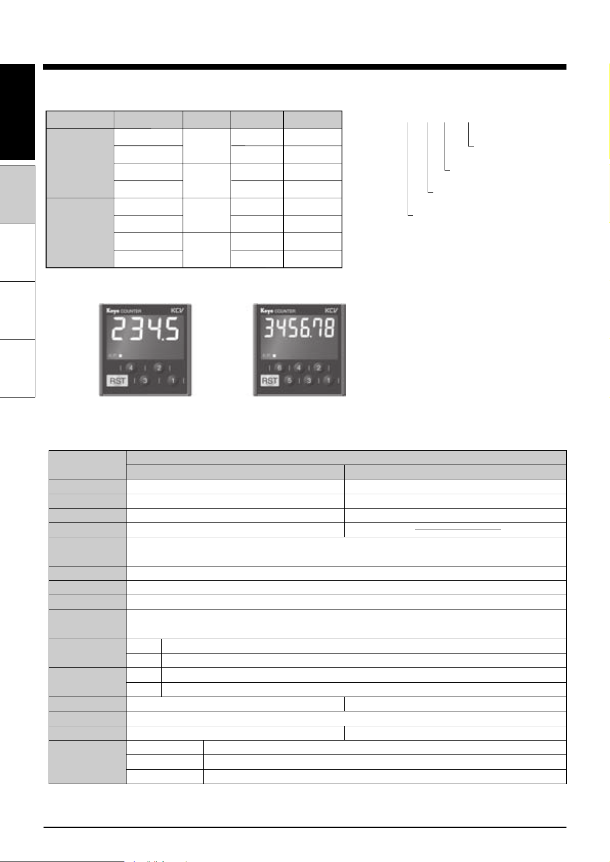
Items that can be configured in Setup Mode
(1)Countingspeed−200/1kHz,Dipswitch1
(2)Inputlogic
−
Positiveornegativelogic
(3)Outputmode
−
Matchoutput,Dipswitch5
(4)Outputduration
−
DurationofOne-shotoutputcanbeset
from10-9990ms(in10-msincrements)
(5)Prescaling
−
4-digit:0.001-9.999
6-digit:0.001-99.999
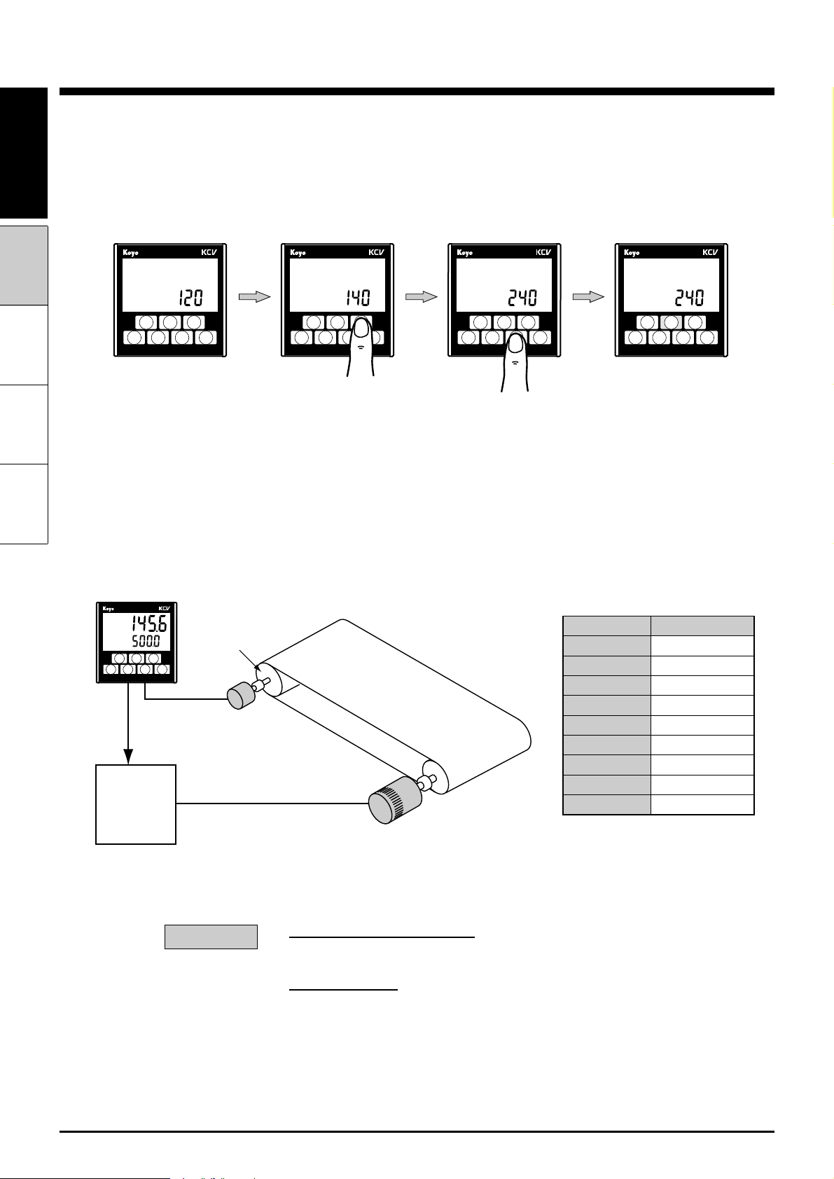
(6)Prescalingfactor
−
Thescalingfactorcanbesetforvalues
usedinprescaling.
1x
10x
100x
1000x
(7)Numberofdigits
−
Thenumberofcounterdigitsfordisplay
canbeset.
4-digit:1-4digits
6-digit:1-6digits
(8)Decimalplace
−
Anarbitrarydigitcanbesetfordisplay
ofthedecimalpoint.
(9)Predictedoutput
−
Offsetvaluescanbesetwithrespectto
presetvalues.
4-digit:0-9999
6-digit:0-999999
(10)Resettingkeyprotection
−
Settingtodisabletheresetkey
canbeperformed.
(11)Protectingdigitkeys
−
Settingtodisableanarbitrary
digitkeycanbeperformed.
※WithaTotalCounter,items3,4,7,9,10,and11areskipped.
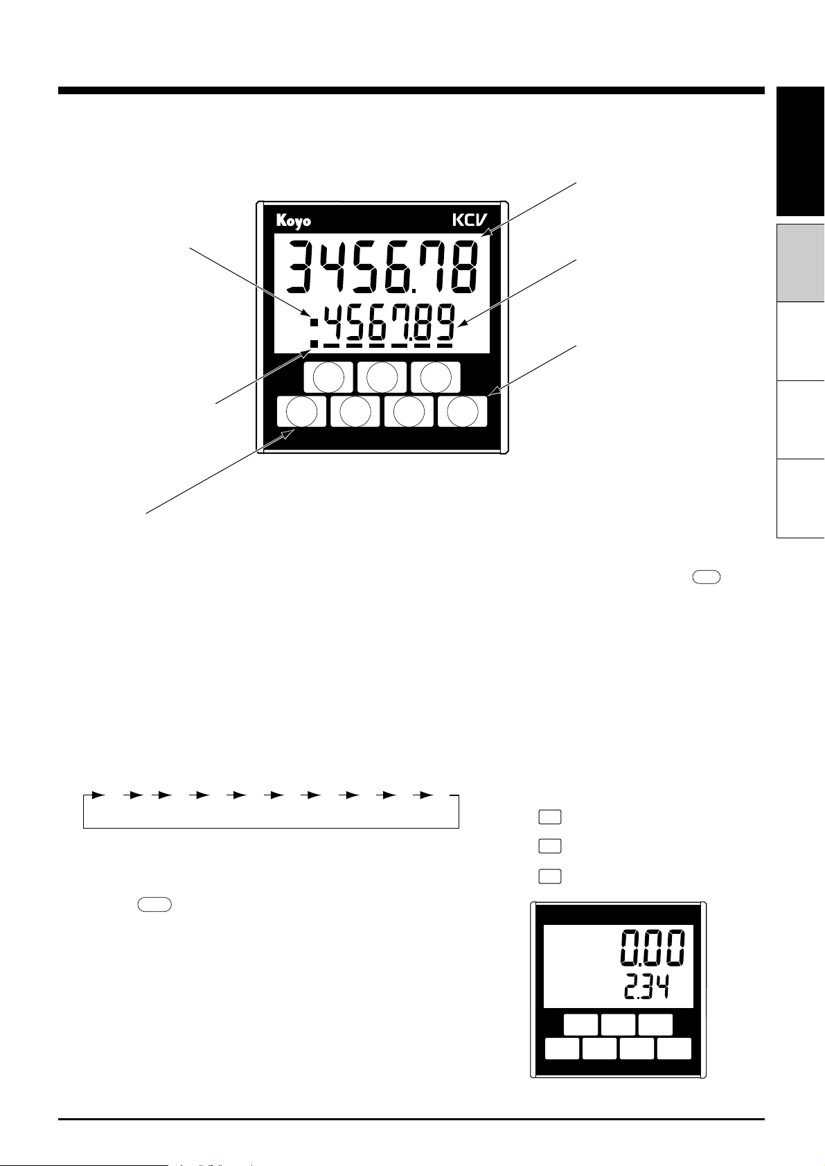
1. Switching Between Setup mode and Run mode
①SettingDipswitch8toONandturningonthepowerwillstartthe
Setupmode.
②SettingDipswitch8toOFFandturningonthepowerwillstart
theRunmode.
2. Operations in Setup mode
InSetupmode,thecountcanbeinitializedusingthemenuas
follows:
*Representsfactorysetup.
■Setup mode