Filtration Group SDG-100 User manual
Translation of the original instructions with installation instructions
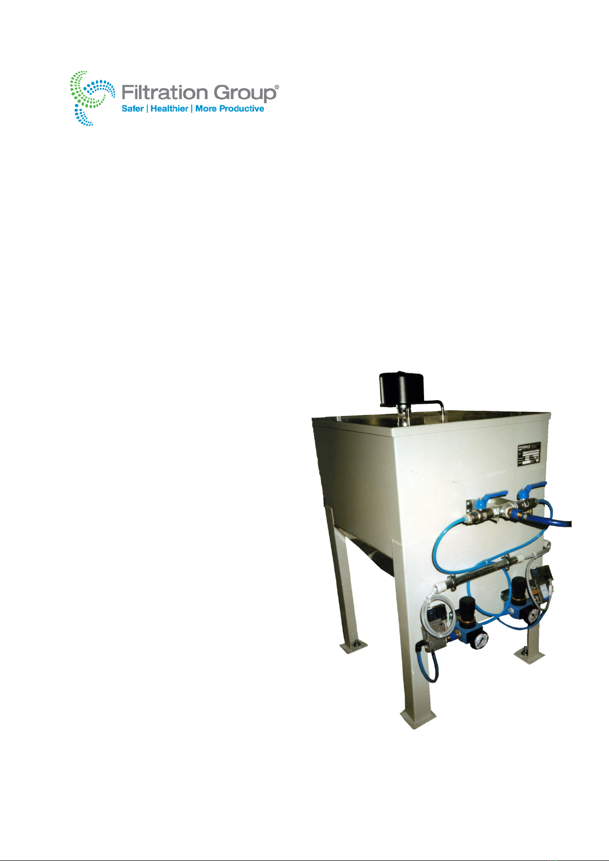
Filter aid dosing device
SDG-100
Mat. No. of original instructions
79792383
Page 2
Translation of the original instructions with installation instructions, Filter aid dosing device SDG-100, Filtration Group GmbH, 16.01.19, Mat. No.
79792383, Version 04
1 Contents
1Contents...................................................................... 2
2General safety instructions....................................... 2
2.1 Safety instructions for installation and
operating personnel .......................................... 2
2.2 Warning structure.............................................. 2
2.3 Warning symbols used...................................... 2
2.4 Other symbols used.......................................... 3
3Glossary...................................................................... 3
4General information ................................................... 3
4.1 Manufacturer..................................................... 3
4.2 Information about the original instructions ........ 3
4.3 Model code ....................................................... 4
5Intended use............................................................... 4
6Functional description............................................... 5
6.1 Principle of the process..................................... 5
6.2 Main components.............................................. 5
7Technical data ............................................................ 6
7.1 General data (excluding optional equipment) ... 6
7.2 Order-specific data............................................ 6
8Transport and storage ............................................... 6
9Installation .................................................................. 6
9.1 Installation......................................................... 7
9.2 Installing the piping / pump selection ................ 7
9.3 Compressed air supply ..................................... 7
9.4 Electrical connections ....................................... 8
9.4.1 Connection of the 2/2-way valves.......... 8
9.4.2 Calibrating the level sensor (optional).... 8
9.4.3 Dosing device controller (optional) ........ 8
10 Start-up ....................................................................... 8
10.1 Initial start-up or start-up after prolonged
shut-down ......................................................... 8
10.2 Starting up the dosing device............................ 8
11 Normal operation ....................................................... 8
12 Shutting down the dust collector ............................. 9
12.1 Temporary shut-down....................................... 9
12.2 Prolonged shut-down (> 48 h)........................... 9
12.3 Emergency shut-down ...................................... 9
12.4 Transporting the dosing device......................... 9
13 Troubleshooting......................................................... 9
14 Maintenance ............................................................... 9
14.1 Inspection and maintenance schedule.............. 9
15 Appendix: Dosing device parameters .................... 10
16 Declaration of incorporation ................................... 11
17 Index.......................................................................... 15
2 General safety instructions
2.1 Safety instructions for installation and
operating personnel
This translation of the original instructions contains
important safety information which must be heeded at all
times during installation, normal operation and maintenance.
Non-observance can result in the following risks to persons
and the environment as well as in damage to the machine or
system:
Failure of critical functions of the machine or system or of
its component parts.
Danger to persons from electrical or mechanical effects
as well as from chemical reactions.
Danger to the environment owing to the leakage of
hazardous substances.
Before installation / start-up:
•Read this translation of the original instructions carefully.
•Make sure that installation and operating personnel are
adequately trained.
•Make sure the contents of the original instructions are
fully understood by the responsible persons.
•Define areas of responsibility and competence.
•Prepare a maintenance schedule.
During operation of the system:
•Keep this translation of the original instructions handy at
the place of use.
•Heed the safety instructions. Always operate the machine
or system in accordance with its ratings.
If in doubt:
•Consult the manufacturer.
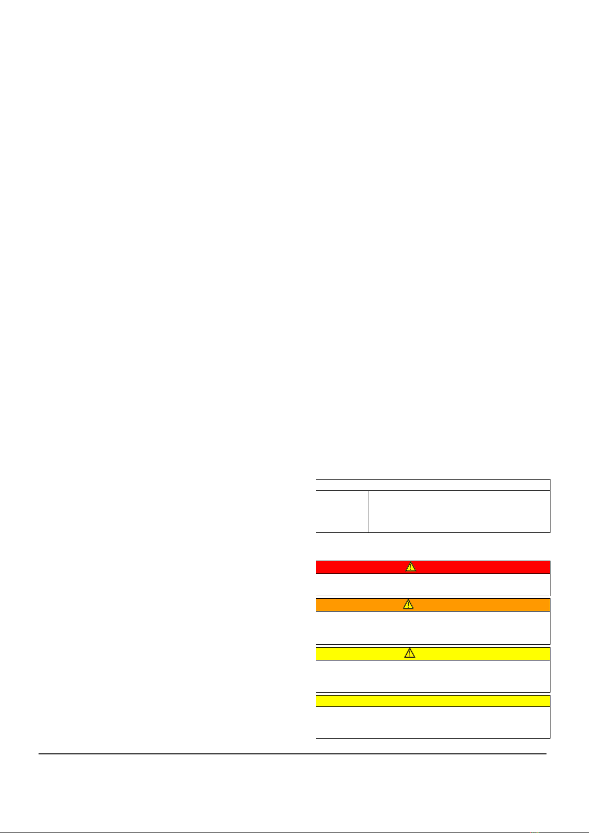
2.2 Warning structure
Where possible, warnings are structured according to the
following system:
Signal word
Possibly
with
symbol
Nature and source of the danger
Potential consequences of non-
observance
•Action to avert the danger.
2.3 Warning symbols used
DANGER!
Immediate danger!
Non-observance will result in serious or fatal injury.
WARNING!
Potentially dangerous situation!
Non-observance can result in serious or fatal injury.
CAUTION!
Potentially dangerous situation!
Non-observance can result in minor or moderate
injuries.
CAUTION! (without a symbol)
Potentially dangerous situation!
Non-observance can result in property damage.
Page 3
Translation of the original instructions with installation instructions, Filter aid dosing device SDG-100, Filtration Group GmbH, 16.01.19, Mat. No.
79792383, Version 04
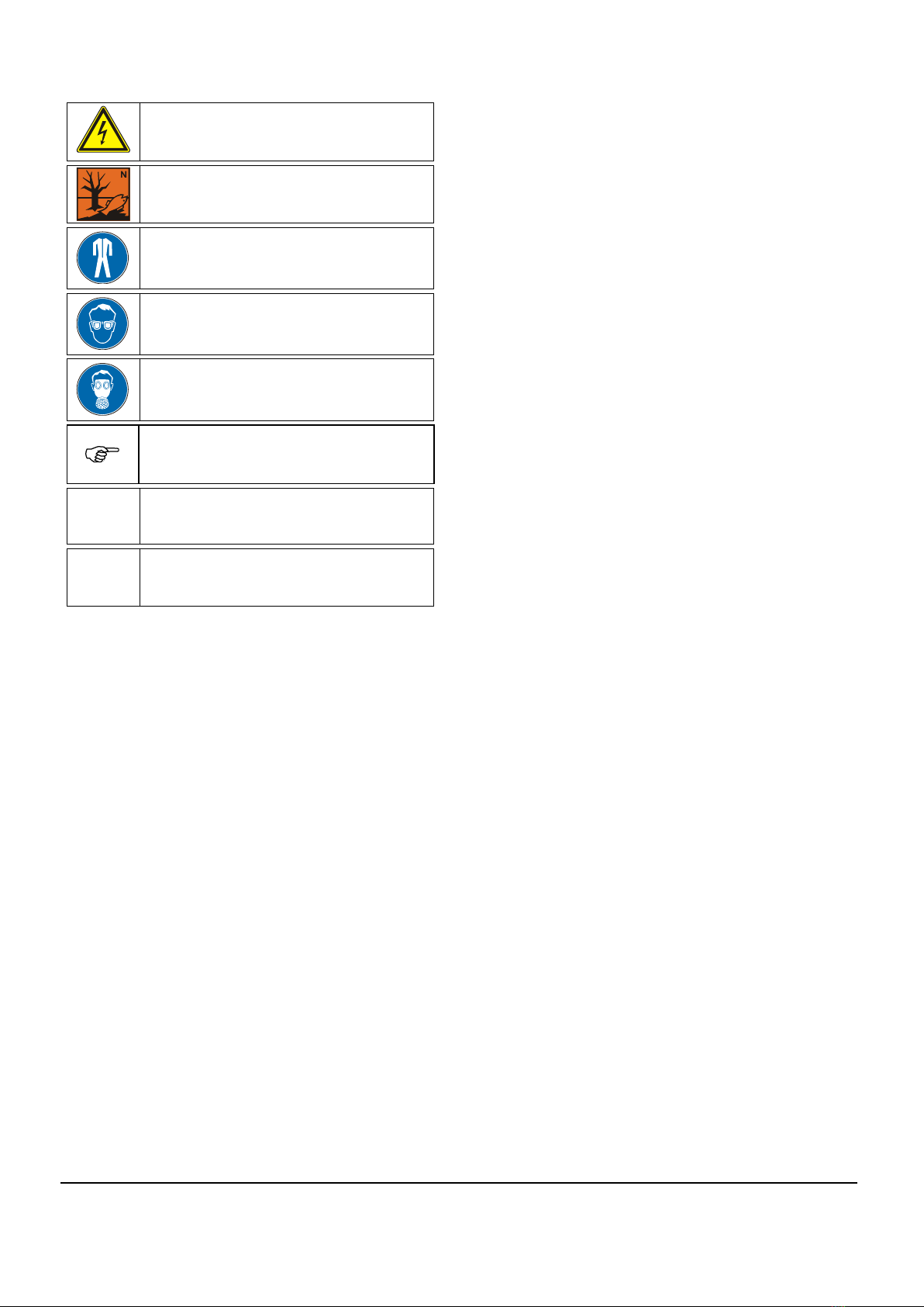
2.4 Other symbols used
Danger: High voltage!
Information about environmental
protection
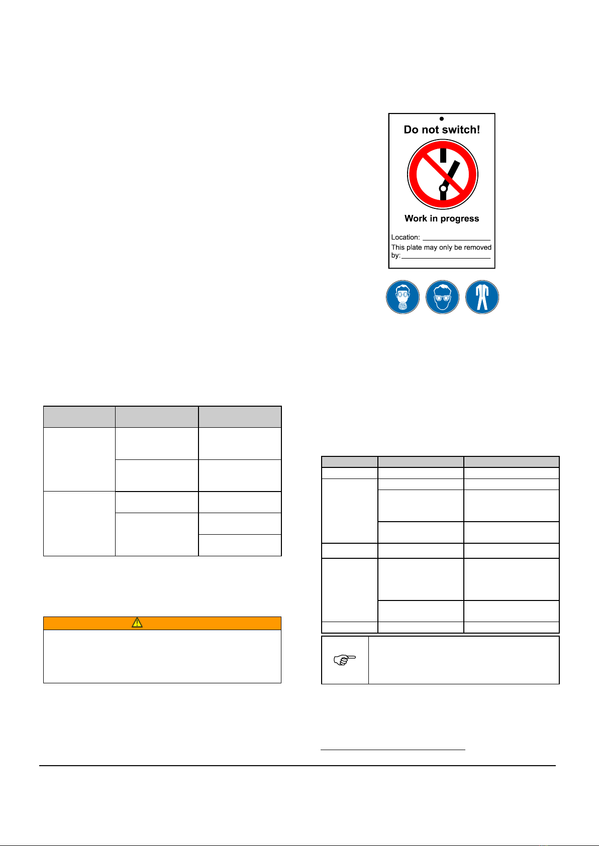
Wear protective clothing!
Eye protection must be worn!
Respirator must be worn!
Hand symbol:
Indicates general information and
recommendations
•
Bullet:
Indicates the order in which
actions are to be carried out
Arrow:
Indicates responses to actions
3 Glossary
System:
Customer’s complete system in which the FG dosing device
is integrated.
Pressure difference / differential pressure:
Pressure difference between the dirty and clean air sides of
the filter in [mbar] or [Pa].
Velocity:
Flow rate through the filter surface. Calculated as the
volume flow divided by the filter area [m³/m² min].
Residual dust content:
Amount of particulate matter on the clean air side [mg/m³].
Dew point:
Temperature at which a gas is saturated with moisture. Mist
droplets form at temperatures below the dew point.
Filter aid:
Powdery aid to facilitate the separation of problem dusts.
Injector nozzle:
Used to add filter aid to the dust-laden air prior to filtration.
4 General information
4.1 Manufacturer
Filtration Group GmbH
Schleifbachweg 45
D-74613 Öhringen
Phone +49 7941 6466-0
Fax +49 7941 6466-429
fm.de.sales@filtrationgroup.com
www.industrial.filtrationgroup.com
4.2 Information about the original instructions
FG Mat. No. ........................................................ 79792383
Date: .................................................................... 16.01.19
Version: .......................................................................... 04

Page 4
Translation of the original instructions with installation instructions, Filter aid dosing device SDG-100, Filtration Group GmbH, 16.01.19, Mat. No.
79792383, Version 04
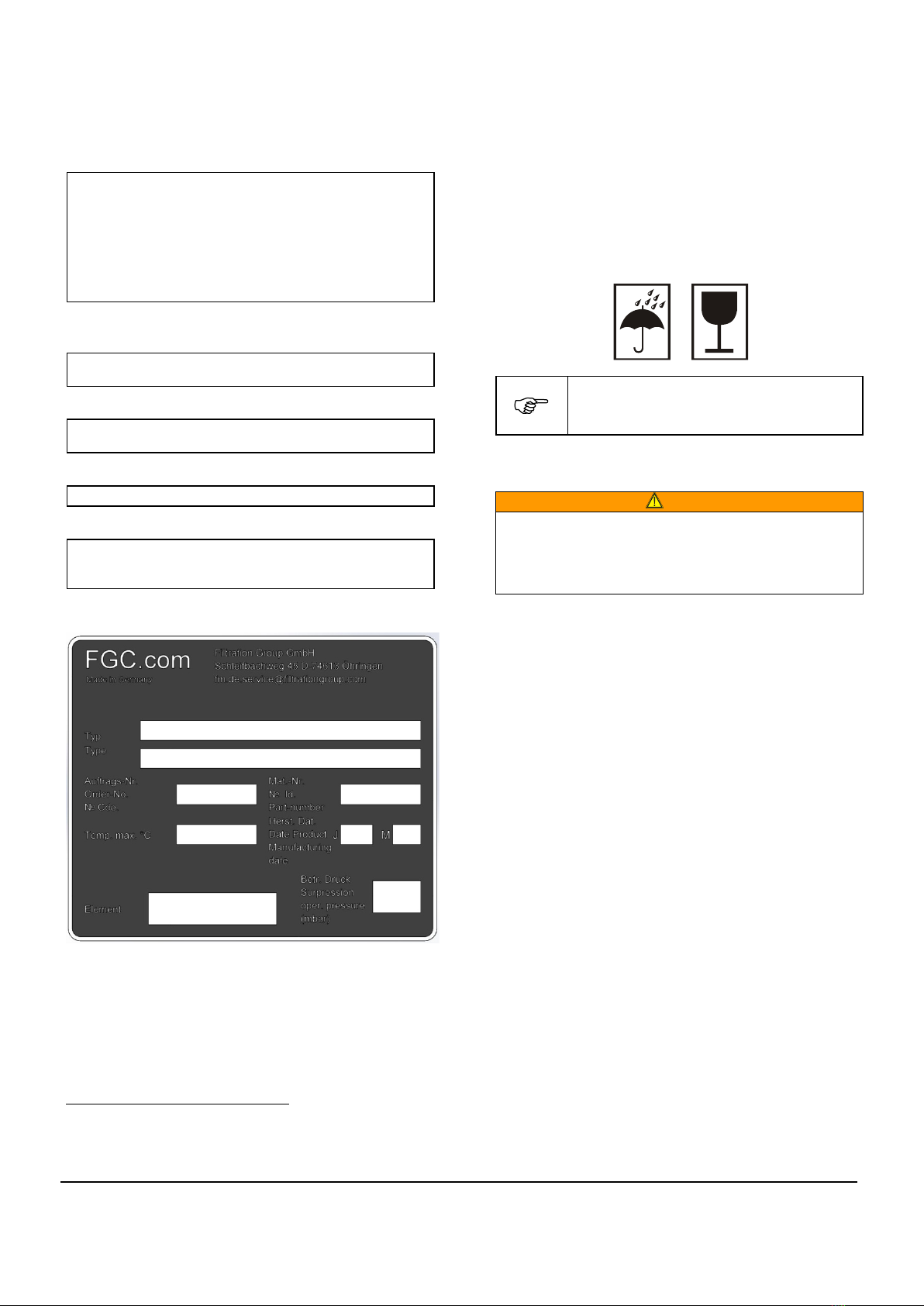
4.3 Model code
(Space for name-plate)
5 Intended use
DANGER!
PROHIBITED:
•Use for other purposes without prior consultation with
the manufacturer.
•Use with smouldering, burning or sticky particles.
•Use with highly explosive dusts (e.g. aluminium dust,
explosives, etc.).
CAUTION!
This FG dosing device is only allowed to be used in
accordance with the operating conditions specified in the
contract documentation and in the original instructions.
All forms of use which deviate from or exceed the limits of
use described above are considered to be contrary to the
intended purpose. The manufacturer is not liable for any
damage resulting from such use.
CAUTION!
Conditionally allowed:
•Use in connection with foodstuffs, provided this is
explicitly confirmed by the manufacturer in the contract
documentation (offer / order confirmation).
The FG dosing device is used in conjunction with an FG
dust collector to separate sticky or very fine dusts. A filter
aid is added to the dust-laden air. The filter aid surrounds
the problem dust and forms a layer on the cleaned filter
elements. The dust is not in direct contact with the filter
element and is thus no longer able to block it or clog it. The
element has a much longer service life as a result.
Problem dust Filter aid Filter element
Bound problem dust
Fig. 1: Principle of the filter aid

Page 5
Translation of the original instructions with installation instructions, Filter aid dosing device SDG-100, Filtration Group GmbH, 16.01.19, Mat. No.
79792383, Version 04
6 Functional description
6.1 Principle of the process
CAUTION!
Abrasive filter aid must NOT be aimed at the wall when it
is added to the dirty air side.
1
The dust-laden air flows into the dirty air side.
2
The dust particles are separated on the filter
elements.
3
The cleaned air enters the clean air side.
4
Fig. 2: Filtration principle
4
Compressed air is applied to the injector nozzle.
A mixture of filter aid and air is fed into the air inlet
pipe. The filter aid forms a layer over the problem
dust and the filter elements.
The filtration process does not need to be interrupted for
cleaning (EXCEPTION: Dust collectors with only one
cleaning valve).
During intermittent operation, the filter aid is added as soon
as the fan is switched on.
6.2 Main components
Fig. 3: Main components
1
Housing
2
Ball valves for shutting off the compressed air
3
DRV 1: Pressure regulating valve for the injector
nozzle
4
Magnetic valve ¼”
5
Injector nozzle
6
Air breather / vent filter
7
DRV 2: Pressure regulating valve for the piston
vibrator
8
Magnetic valve ¼”
9
Piston vibrator (concealed)
Level sensor (optional):
Sensor for monitoring the minimum level in the filter aid
tank. An electrical signal is output if the level falls below this
minimum value.
Air injector loosening system
The air injector loosening system is used to
fluidise powdery products. Bridging is
prevented in this way and the powder is
discharged uniformly.
Fig. 4: Accessories for the dosing device
3
2
1
Air injector loosening
system
Air injector loosening
system
Page 6
Translation of the original instructions with installation instructions, Filter aid dosing device SDG-100, Filtration Group GmbH, 16.01.19, Mat. No.
79792383, Version 04
7 Technical data
7.1 General data
(excluding optional equipment)
Dosing device housing (standard version):
Material: .......................................................... Sheet steel
Surface finish: .................................... EPS plastic coating
Colour: ............................................ RAL 7035 (light grey)
Seals:......................................................... Natural rubber
Max. operating temperature: ..................................... 40°C
Max. operating pressure: .......................................... 7 bar
Capacity: ................................................................... 100 l
Dosing rate:....................... Approx. 10 g/s (see Appendix)
Other materials available for special applications.
Pneumatic power consumption:
Compressed air:................................................. 6 bar, dry
Consumption per dosing cycle: .................. Approx. 2 m³N
*
Electrical power consumption:
Magnetic valves: ...................................... 24 VDC / 4.5 W
Cyclic duration factor:............................................... 100%
Noise emission (partially optional):
Continuous sound pressure level:.................. < 70 dB(A)
**
Ambient conditions:
Ambient temperature:......................................... 5 to 40°C
Floor:............................. Level surface, free from vibration
Atmosphere:................................................ Non-corrosive
7.2 Order-specific data
The order-specific data can be taken from the name-plate.
*N = Normal conditions (roughly equivalent to the “suction
capacity” of a compressor)
** Test set-up: Distance from the dust collector: 1 m,
height above floor: 1.60 m
8 Transport and storage
Transport
•The transport lock must not be removed until the system
has reached its place of use.
•Do not lift the dosing device by the handles.
Storage
•Always store in the original packaging.
•Always store in a dry, frost-free room.
Seaworthy packaging is specified in the
contract documentation as an option.
9 Installation
WARNING!
If the system is installed by unauthorised persons:
Risk of injury.
All warranty claims are rendered invalid.
•The system must be installed by a suitably trained
person!

Page 7
Translation of the original instructions with installation instructions, Filter aid dosing device SDG-100, Filtration Group GmbH, 16.01.19, Mat. No.
79792383, Version 04
9.1 Installation
CAUTION!
•Do not install in the vicinity of devices which are
sensitive to vibration.
•Do not lift using the handles!
•Install the dosing device as close as
possible to the dust collector.
•Avoid long distances (> 5 m).
•Lift the dosing device off of the pallet and place it in
position.
•Align the dosing device so that it is exactly level.
•Bolt the dosing device tightly to a firm surface (use
dowels).
•Do not install the dosing device outdoors or in damp
areas.
Fig. 5: Installation
9.2 Installing the piping / pump selection
•All connections must be properly secured (e.g. with
clamps, clamp rings, flange joints, etc.).
•Check that all connections are tight.
9.3 Compressed air supply
CAUTION!
•Lay pipes WITHOUT STRESS!
•Lay hoses so that they CANNOT BE KINKED!
•Keep hoses clear of aisles!
Compressed air quality:
•Oil and water-free
•Free of debris
•Pressure p = 6 bar
•For quality grades, refer to PNEUROP 2001
Connection of the 2/2-way valves:
A: Piston vibrator, filter aid valve
P: Compressed air supply
Fig. 6: Pneumatic connections of the 2/2-way valves
•Install a separate air pressure reducer and
possibly a filter close to the dosing device.
•Install a suitable compressed air shut-off
valve in a readily accessible position (for
maintenance work, etc.).
•Connect the dosing hose to the air inlet pipe.
•All connections must be properly secured (e.g. with
clamps, clamp rings, flange joints, etc.).
•Check that all connections are tight.
•Supply compressed air (1/2”i) to the dosing device.
A
P
3.5 m

Page 8
Translation of the original instructions with installation instructions, Filter aid dosing device SDG-100, Filtration Group GmbH, 16.01.19, Mat. No.
79792383, Version 04
9.4 Electrical connections
DANGER!
Danger of electric shock!
Risk of serious or fatal injury in case of
contact with electrical components.
All electrical installation work must be
carried out by a qualified electrician!
9.4.1 Connection of the 2/2-way valves
DC power supply:.................................24 VDC, 4.5 W
AC power supply (optional): .................... 230 VAC, 16 VA
Fig. 7: Electrical connections of the 2/2-way valves
9.4.2 Calibrating the level sensor (optional)
•Refer to the separate instructions.
9.4.3 Dosing device controller (optional)
The dosing device is controlled by means of an FG
controller.
•Refer to the separate instructions.
10 Start-up
DANGER!
This device must not be put into service until the relevant
machinery into which it is to be incorporated has been
declared in conformity with the applicable EC directives,
harmonised standards, European standards or equivalent
national standards.
10.1 Initial start-up or start-up after prolonged
shut-down
•Inspect all system components.
•Remove all parts that do not belong (e.g. tools,
installation waste, etc.).
•Check the pipe connections (e.g. clamps).
•Tighten all screws and bolts.
10.2 Starting up the dosing device
•Connect the compressed air supply.
•Switch on the controller.
•Check the level in the filter aid tank.
11 Normal operation
DANGER!
Danger due to high pressure in the dust collector!
Risk of injury to persons or damage to property.
Shut off the compressed air and vent the system prior to
working on devices with an air injector loosening system!
Always dispose of the concentrate in an
environmentally responsible way!
Consult the responsible authorities before
deciding upon the most suitable disposal
method.
The dosing device works largely automatically during normal
operation.
•Check the dosing device in accordance
with the inspection and maintenance
schedule (refer to section 14.1).
Topping up the filter aid
•Wear protective clothing and equipment appropriate to
the hazard potential of the medium (e.g. eye protection,
respirator, protective clothing, etc.).
•Shut off the compressed air and vent the system prior to
working on devices with an air injector loosening system!
24 VDC
230 VAC
*
A
P
Page 9
Translation of the original instructions with installation instructions, Filter aid dosing device SDG-100, Filtration Group GmbH, 16.01.19, Mat. No.
79792383, Version 04
12 Shutting down the dust collector
12.1 Temporary shut-down
•Switch off the fan or shut down the dusty system.
•Switch off the dosing device controller.
•Switch off the compressed air supply.
12.2 Prolonged shut-down (> 48 h)
•Empty the filter aid tank.
•Blow the injector nozzle clean several times (either
manually or by means of the controller).
•Switch off the fan or shut down the dusty system.
•Switch off the dosing device controller.
•Switch off the compressed air supply.
•Disconnect any electrical connections.
•Carry out the maintenance work.
12.3 Emergency shut-down
•Activate the EMERGENCY STOP device (e.g. mushroom
button, to be provided by the customer).
12.4 Transporting the dosing device
•Shut down the dosing device as described in section
12.2.
•Disconnect the compressed air supply.
•Disconnect the electrical connections.
•Transport the dosing device as described in section 8.
13 Troubleshooting
Fault
Possible cause
Remedy
No filter aid
supplied
Tank empty
Top up the filter
aid (refer to
section 11)
Not enough
compressed air
Check the air
pressure
(6 bar)
Filter elements
clogged
Injector clogged
Blow out the
injector
Dosing rate too
low
Select a shorter
interval time
Select a longer
pulse time
•For all other faults, please contact FG Customer Service.
14 Maintenance
WARNING!
If the system is maintained by unauthorised persons:
Risk of injury.
All warranty claims are rendered invalid.
All maintenance work must be carried out by a suitably
trained person!
Before all maintenance work:
•Shut down the dust collector / system / dosing device.
•Switch off the compressed air supply.
•Take steps to prevent the machine / system from being
switched on again by unauthorised persons.
•Wear protective clothing and equipment appropriate to
the hazard potential of the medium (e.g. eye protection,
respirator, protective clothing, etc.).
•Carry out the maintenance work.
•Start up the dust collector / system / dosing device again.
•Observe the dust collector / system / dosing device.
•Does it operate normally?
14.1 Inspection and maintenance schedule
•See also contract documentation.
Interval
Component
Activity
Daily
Storage tank
Check the level
Weekly
Dosing device
Visual inspection
Compressed air
maintenance unit
Visual inspection
Empty the water
separator
Tank
Visual inspection, top
up if necessary
1
Monthly
Connections
Tighten
Yearly
(or
whenever
necessary)
Compressed air
connections
Check
Air breather
Replace the filter
element
Regularly
Filter mat in cover
Clean
The necessary inspection and maintenance
work is dependent on the particular
application.
Please consult the manufacturer if necessary.
1Check more often with short cleaning cycles.

Page 10
Translation of the original instructions with installation instructions, Filter aid dosing device SDG-100, Filtration Group GmbH, 16.01.19, Mat. No.
79792383, Version 04
15 Appendix: Dosing device parameters
Date
Piston vibrator
Injector
Dosing rate
Remarks
Pressure
Duration
Interval
Pressure
Duration
Interval
HI 26
bar
s
s
s
s
s
kg/h
Example
6
1.5
120
5
1
10
3.3
Page 11
Translation of the original instructions with installation instructions, Filter aid dosing device SDG-100, Filtration Group GmbH, 16.01.19, Mat. No.
79792383, Version 04
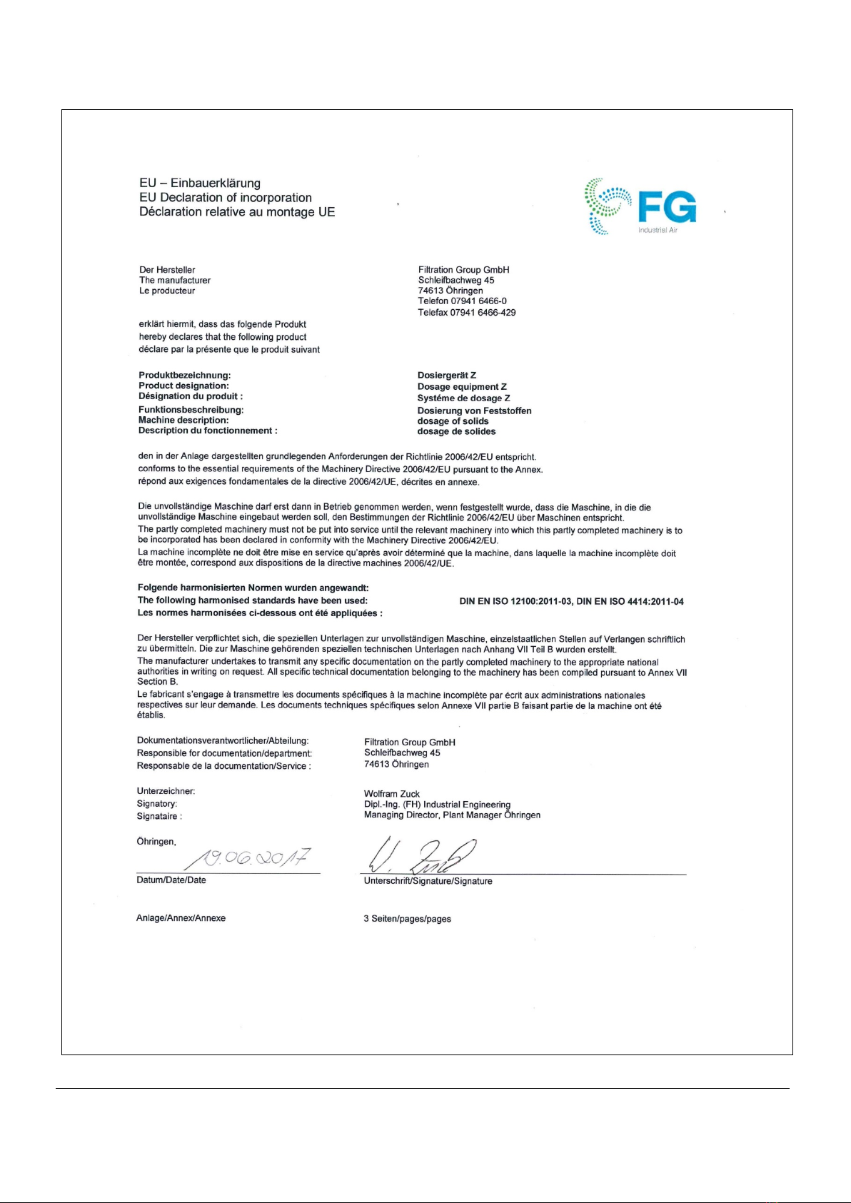
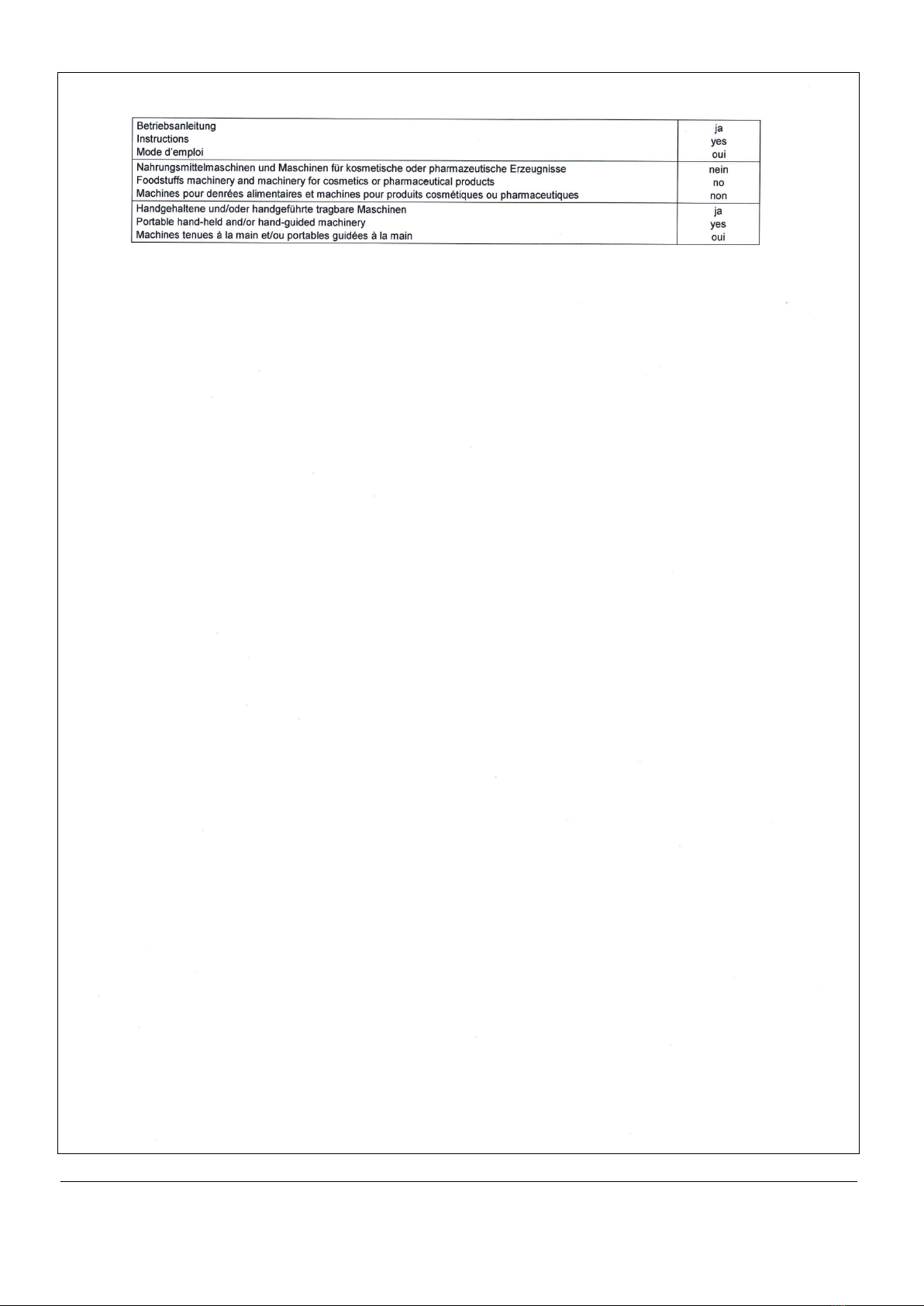
16 Declaration of incorporation
As defined by the EC Machinery Directive

Page 12
Translation of the original instructions with installation instructions, Filter aid dosing device SDG-100, Filtration Group GmbH, 16.01.19, Mat. No.
79792383, Version 04

Page 13
Translation of the original instructions with installation instructions, Filter aid dosing device SDG-100, Filtration Group GmbH, 16.01.19, Mat. No.
79792383, Version 04
Page 14
Translation of the original instructions with installation instructions, Filter aid dosing device SDG-100, Filtration Group GmbH, 16.01.19, Mat. No.
79792383, Version 04

Page 15
Translation of the original instructions with installation instructions, Filter aid dosing device SDG-100, Filtration Group GmbH, 16.01.19, Mat. No.
79792383, Version 04
17 Index
C
Clean air side..................................................................... 5
Cleaning............................................................................. 5
Compressed air ......................................................... 6, 7, 9
Compressed air supply ...................................................... 7
Concentrate ....................................................................... 8
Continuous sound pressure level....................................... 6
Contract documentation..................................................... 4
D
Dew point........................................................................... 3
Dirty air side....................................................................... 5
Dosing cycle ...................................................................... 6
E
Environmental protection ................................................... 3
F
Fan .................................................................................... 9
Filter aid............................................................................. 3
Filter elements ................................................................... 9
I
Injector nozzle.................................................................... 3
L
Leakage............................................................................. 2
Level sensor.......................................................................8
M
Magnetic valve ...................................................................6
Manufacturer ..................................................................2, 4
P
Pilot control.........................................................................3
Pressure difference ............................................................3
Problem dust ......................................................................4
Protective clothing and equipment .................................8, 9
R
Residual dust content.........................................................3
Risks...................................................................................2
Rotating wing......................................................................7
S
Safety instructions ..............................................................2
Seaworthy packaging .........................................................6
V
Valves.................................................................................3
Velocity...............................................................................3
W
Warning ..............................................................................2

Filtration Group GmbH
Schleifbachweg 45
D-74613 Öhringen
Phone +49 7941 6466-0
Fax +49 7941 6466-429
fm.de.s[email protected]
www.industrial.filtrationgroup.com
77972383.I04.01/2019
Table of contents
Popular Dispenser manuals by other brands

Franke
Franke DVS SD99-009 Installation and operating instructions

Heinz
Heinz Keystone AF08 user manual

Lacava
Lacava EX26 owner's manual

Igloo
Igloo IGLWCRFTL353CRHWH instruction manual

Hilti
Hilti HIT-P 8000 D Original operating instructions

Lily Corporation
Lily Corporation CD65 Operation and service manual


GESAME
GESAME MH Super 114 instruction manual

Scotsman
Scotsman Meridian HID Series manual

Coastwide Professional
Coastwide Professional ExpressMix instruction manual

Fisherbrand
Fisherbrand 12867913 instruction manual

ViscoTec
ViscoTec preeflow eco-DUOMIX450 Operation & maintenance manual

Keurig
Keurig K10 Mini Plus owner's manual