DEMA Nitro Express User manual

I-974
Rev. J-43
Overv
i
The DEMA
and dish ma
c
p
otentiomet
e
Warni
n
816 3/
2
ew
Nitro Express
c
hines. The u
n
e
rs and dip sw
i
n
gs
Installat
i
b
y natio
n
regulati
o
For que
s
All inst
a
devices.
codes in
ALWA
Y
CHEM
I
2
3/18
D
Ware
is an analog
w
it is triggered
b
i
tches.
i
on of DEMA
p
n
al, city, coun
t
o
ns require tha
t
s
tions, contact
a
llations must
c
A pressure in
d
the state of W
Y
S WEAR P
R
I
CAL PROD
U
D
EMA
N
Wash
C
w
are wash disp
e
b
y a ware was
h
p
roducts must
t
y, parish, pro
v
t
a certified el
e
a
certified ele
c
c
onform to loc
a
d
icating tee is
t
isconsin and a
n
R
OTECTIVE
C
U
CTS.
N
itro E
x
C
hemica
l
e
nser designe
d
h
machine. Pr
o
meet all appli
c
v
incial or othe
r
e
ctrical contra
c
c
trician.
a
l plumbing c
o
t
o be installed
w
n
y other state
t
C
LOTHING A
N
x
press
l
Dispe
n
d
to dispense c
l
o
gramming is
a
c
able electrica
l
r
agencies. It i
s
c
tor or enginee
r
o
des and use a
p
w
ith existing
f
t
hat requires t
h
N
D EYEWE
A
Pa
g
n
se
r
l
eaning chemi
c
a
ccomplished
t
l
codes and re
g
s
possible that
e
r
perform the
e
p
proved backf
l
f
aucets accordi
h
e use of a pre
s
A
R WHEN W
O
g
e 1 of 8
c
als into ware
w
t
hrough the us
e
g
ulations estab
l
e
lectrical code
e
lectrical insta
l
l
ow preventio
n
ng to local pl
u
s
sure indicatin
g
O
RKING WIT
H
w
ash
e
of
l
ished
s and
l
lation.
n
u
mbing
g
tee.
H
I-974
Rev. J-43816 Page 2 of 8
3
/
23/18
Packing List
X = included in kit
Part Number
Description
NE.DL.A
NE.LL.A
NE.DLL.A
NE.LLL.A
904.8T RINSE CHECK VALVE ¼” OD TEFLON BALL
X
X
X
X
80.55 LIQUID DETERGENT FEED INJECTION ELBOW
X
X
81.312.1 SPLIT PICK UP TUBE STIFFENER
1
2
2
3
25.68.20 20 FT ¼” OD LDPE TUBING
X
X
X
X
C.12B CONDUCTIVITY CELL
X
X
X
X
100.12.SV1 VINYL RINSE TUBING
X
X
X
X
58.5 OVERFLOW ELBOW KIT – DRY DETERGENT
X
X
904.8KY RINSE CHECK VALVE ¼” COMP X 1/8” NPT KYNAR
X
X
81.16.1 TIE WRAPS 8” LONG
5
5
8
8
I974 INSTRUCTION SHEET
X
X
X
X
Operational Requirements
For indoor use only
Trigger Signal Inputs 115/230VAC 50/60 Hz 1.5A
Motors/Solenoid Valves 24VDC
Detergent Pump Rate 6oz/min (180ml/min)
Rinse/Sanitizer Pump Rate 1.3oz/min (40ml/min)
Operating Temp 4-30°C 40-100°F
Case Material ABS
The integrity and operational characteristics of this unitare not guaranteedoutside the above
mentionedparameters.Useofthisunitoutsideoftheseparametersnullifieswarranty.
This unit will only accept up to 265 VAC. It cannot accept over this amount. If more than 265
VAC is supplied to this unit, critical damage will occur.
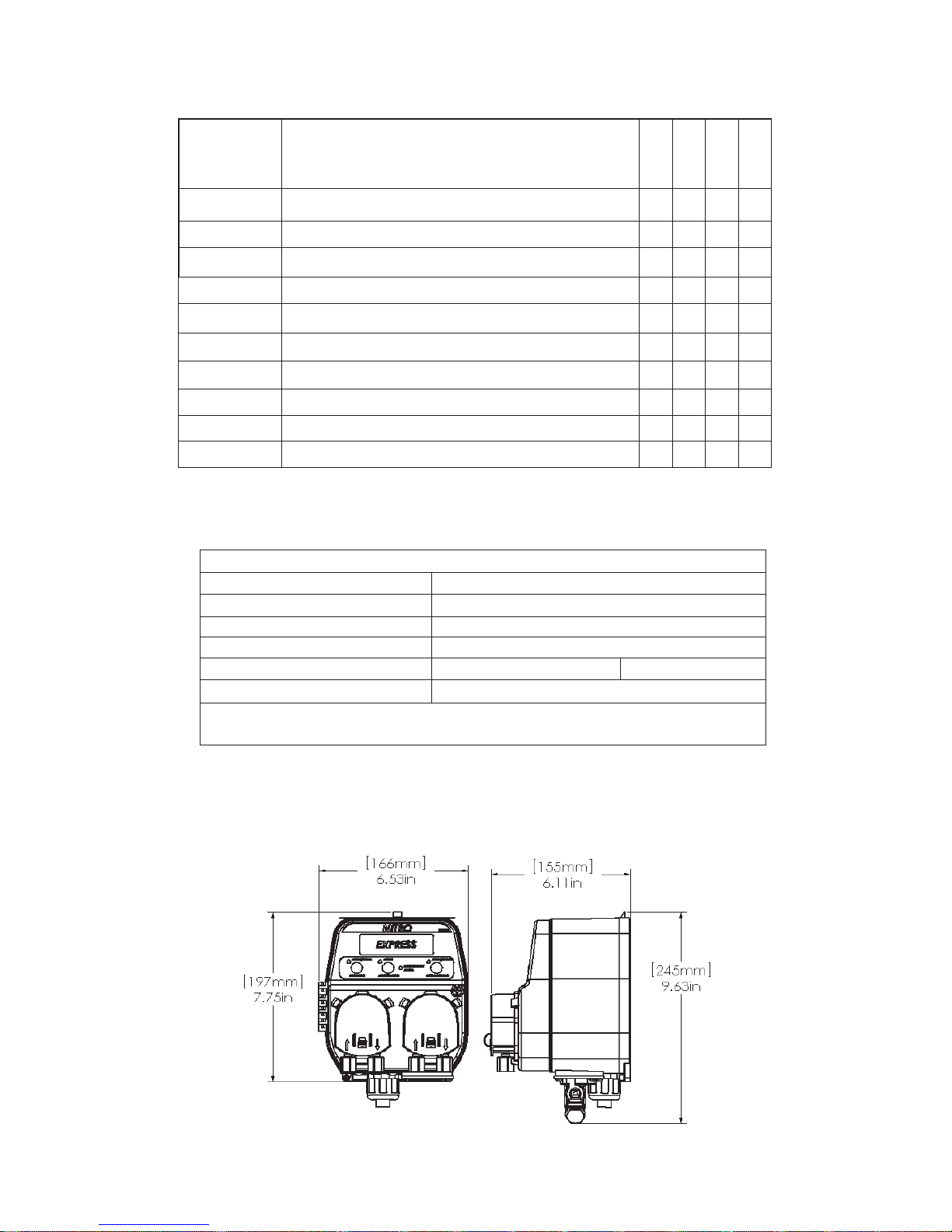
Overall Size

I-974
Rev. J-43816 Page 3 of 8
3
/
23/18
Replacement Parts List
81.316.6 NITRO/NITRO EXPRESS DETERGENT
VALVE CONV. AND REPLACEMENT KIT
58.104.2- J.G. ELBOW FITTING FOR VALVE
81.316.7 NITRO/NITRO EXPRESS
SANITIZER PUMP CONVERSION
KIT INCLUDING CONTROL BOARD
(NOT SHOWN)
O.A DC NITRO/NITRO EXPRESS
SANITIZER PUMP WITH TUBING
AND ACCESORIES
Model shown is of a NE.LL.A
NO. KIT NO. DESCRIPTION
1 81.316.1
NITRO/NITRO EXPRESS POWER SUPPLY REPLACEMENT KIT (TRIGGER OUTPUT
TRANSFORMER)
2 81.316.2 CONTROL BOARD NITRO EXPRESS FOR 2 PRODUCT (DETERGENT/RINSE)
81.316.3 CONTROL BOARD NITRO EXPRESS WITH SANITIZER (3 PRODUCT)
3 81.316.4 NITRO/EXP. DETERGENT PUMP HEAD AND MOTOR CONV. AND REPLACEMENT KIT
81.316.10 NITRO/NITRO EXPRESS DETERGENT MOTOR ONLY REPLACEMENT KIT
81.316.6 NITRO/NITRO EXPRESS DETERGENT
V
ALVE CONVERSION AND REPLACEMENT KIT
4 81.316.5 NITRO/NITRO EXPRESS RINSE PUMP HEAD AND MOTOR REPLACEMENT KIT
81.316.11 NITRO/NITRO EXPRESS RINSE MOTOR ONLY REPLACEMENT KIT
5
81.316.8 NITRO/NITRO EXPRESS DETERGENT PUMP HEAD ONLY REPLACEMENT KIT
81.316.9 NITRO/NITRO EXPRESS RINSE PUMP HEAD ONLY REPLACEMENT KIT
25.21.4 SINGLE SQUEEZE TUBE REPLACEMENT
25.21.5 BULK (5) SQUEEZE TUBE REPLACEMENT
6 L1115 MEMBRANE LABEL
7 81.275.1 MOUNTING BRACKET

I-974
Rev. J-43
Install
a
ALL ELE
C
MACHINE
UNIT MUS
Mountin
g
t
h
1. Re
m
2. M
o
3. Sli
d
Settin
g
up t
1. Lo
c
ma
n
2. Pr
o
3. If t
h
12
B
of
t
4. Ins
t
rea
d
5. Ins
t
ma
c
6. Ins
t
ma
n
thi
s
Connectin
g
1. Aft
e
co
n
an
d
2. Cu
t
ch
e
3. Me
4. Cu
t
Clasp Clos
e
The pum
p
help to ensu
r
When
p
ushi
n
clip is fully
c
p
icture. If t
h
p
ossibility o
the second
p
Wirin
g
the
N
The followi
n
816 3/
2
a
tion
WARN
I
ELECT
COUN
T
ELECT
ELECT
INSTA
L
C
TRICAL PO
W
PRIOR TO
B
T BE GROU
N
h
e Nitro Exp
r
m
ove mountin
g
unt the
b
racke
t
d
e the dispens
e
he Nitro Exp
r
c
ate the electri
c
n
ufacturer of t
h
perly ground t
h
h
e Nitro Expr
e
B
probe in the
w
t
he tank, and
m
t
all the deterg
e
d
ing of all che
m
t
all the rinse li
n
c
hine. If a tap
i
t
all the sanitiz
e
n
ufacturer of t
h
s
fitting.
the Chemica
l
e
r mounting t
h
n
tainers. The d
e
d
sanitizer tubi
n
t
the tubing to
t
e
mical contain
e
asure the leng
t
t
the tubing to
t
e
Pump Head
s
p
heads have
a
r
e the pump h
e
n
g the pump h
e
c
overing the n
o
h
e tab is not ful
f it popping o
f
p
icture.
N
itro Expres
s
n
g diagram is i
n
WARN
I
OVER
T
WARN
I
tri
gg
er
s
manufa
c
UNIT
M
2
3/18
I
NG: INSTA
L
R
ICAL COD
E
T
Y, PARISH,
R
ICAL COD
E
R
ICAL CON
T
L
LATION. F
O
W
ER MUST
B
B
EGINNING
N
DED (EAR
T
r
ess
g
bracket from
t
in an appropr
i
e
r onto the
b
ra
c
r
ess and the
D
c
al connection
h
e machine to
d
h
e dispenser t
o
e
ss will be ope
r
w
ash tank. Th
e
m
ust be kept a
w
e
nt injection b
u
m
icals enterin
g
n
e injection fit
t
i
s not provide
d
e
r injection fitt
i
h
e machine. If
l
Tubin
g
to th
h
e dispenser,
m
e
tergent tubin
g
n
g (100.12.SV
t
he length req
u
e
r.
t
h of tubing ne
e
t
he length req
u
s
a
n added featu
r
e
ad is installed
e
ad on be sure
o
tch as seen in
ly engaged, th
e
f
f the pump he
a
s
to the Dish
M
n
cluded to hel
p
I
NG: ONLY
U
T
HAT AMO
U
I
NG: For safe
t
s
i
g
nals to the
N
c
turer’s reco
m
M
UST BE GR
O
L
LATION O
F
E
S AND RE
G
P
ROVINCI
A
E
S AND RE
G
T
RACTOR
O
O
R QUESTI
O
B
E TURNED
INSTALLA
T
T
HED).
dispenser.
i
ate place on a
c
ket and attach
D
ish Machine
point. The in
p
d
etermine if t
h
o
earth ground.
r
ating in the c
o
e
probe must
be
w
ay from heati
n
u
lkhead fitting
g
the wash tan
k
t
ing (904-8T)
i
d
, follow the
m
i
ng (904-8KY
)
a tap is not pr
o
e
Nitro Expr
e
m
easure the len
g
g
(25.68.20) is
1) which is cle
a
u
ired and, if de
s
e
ded to go fro
m
u
ired to reach t
h
r
e which will
properly.
to see the
the first
e
re is a
a
d as seen in
M
achine
p
to install the
U
P TO 265 V
A
U
NT WILL C
A
ty
purposes d
i
N
itro Express
m
mendations.
O
UNDED (E
A
F
DEMA PRO
G
ULATIONS
A
L OR OTHE
R
G
ULATIONS
O
R ENGINE
E
O
NS, CONTA
C
OFF TO TH
E
T
ION
wall.
the secure scr
e
p
ut power may
h
ere are dedica
t
o
ncentration m
o
e
installed
b
elo
w
n
g elements, p
u
(80-55) above
k
.
i
nto the rinse l
i
m
anufacturer’s
r
)
(if sanitize
r
i
s
o
vided follow
t
e
ss
g
th of tubing n
e
opaque in col
o
a
r in color and
s
ired, place th
e
m
the dispense
r
h
e bulkhead fi
t
wires in the c
o
A
C SHOULD
A
USE CRITI
C
i
sconnect mai
. Connect po
w
A
RTHED).
O
DUCTS MU
S
ESTABLISH
R
AGENCIE
S
REQUIRE T
H
E
R PERFOR
M
C
T A CERTI
E
HEATING
e
w on the
b
ott
o
be 100V – 26
5
t
ed terminals a
o
de, locate the
w
the water le
v
u
mp intake, dr
a
the probe (if
a
ine tap provid
e
r
ecommendati
o
s
used) into th
e
t
he manufactu
r
e
eded to go fr
o
o
r and has a la
r
has a small in
s
e
pickup tube
o
r
to the chemic
t
ting or chemi
c
o
rrect places f
o
BE SUPPLI
E
C
AL DAMA
G
i
n power to th
w
er to the Nit
r
Pa
g
S
T MEET AL
H
ED BY NAT
I
S
. IT IS POS
S
H
AT A CER
T
M
THE ELE
C
FIED ELEC
T
ELEMENTS
o
m left corner
o
5
V 50/60 Hz.
C
a
vailable for in
s
proper
p
ositio
n
v
el, normally 1
a
ins and inco
m
a
probe is used
)
e
d by the man
u
o
ns for installi
n
e
rinse line tap
r
er’s recomme
o
m the dispens
r
ger inside dia
m
s
ide diameter.
o
n the tubing
be
al injection po
c
al injection p
o
o
r proper pow
e
E
D TO THIS
U
G
E TO THE
U
e dish machi
n
r
o Express pe
r
g
e 4 of 8
L APPLICA
B
I
ONAL, CIT
Y
S
IBLE THAT
T
IFIED
C
TRICAL
T
RICIAN.
AND DISH
o
f the dispens
e
C
heck with th
e
s
tallation.
n
for the DEM
A
-2” from the
bo
m
ing water sup
p
)
to obtain a ra
p
u
facturer ofth
e
n
g this fitting.
provided by t
h
e
ndations for i
n
er to the chem
i
m
eter than the
r
e
fore placing i
n
int on the ma
c
o
int on the ma
c
e
r for the unit.
U
NIT. ANYT
H
U
NIT.
n
e before wiri
n
r
the dish ma
c
B
LE
Y
,
e
r.
e
A C-
o
ttom
p
ly.
p
id
e
h
e
n
stalling
i
cal
rinse
n
the
c
hine.
c
hine.
H
ING
ng
c
hine

I-974
Rev. J-43816 Page 5 of 8
3
/
23/18
The following steps will help to insure the proper wiring of the unit. The unit should be triggered to power on from the
dish machine that it is being used in conjunction with. DEMA Engineering does not recommend powering the unit
separately from the dish machine. The following three steps will insure that the unit only receives power when it is
necessary to have power to run the setup that is programmed in the unit.
1. Connect the wash trigger (white and brown wires) to the appropriate wash trigger output (between 100 and 265
VAC 50/60Hz) as recommended by the dish machinemanufacturer.
2. Connect the rinse trigger (black and red wires) to the appropriate rinse trigger output (between 100 and 265
VAC 50/60 Hz) as recommended by the dish machine manufacturer.
3. Make sure to connect the earth ground (green wire) to the ground connection on the dish machine as
recommended by the dish machine manufacturer.
If there is ever any question about the connection to the dish machine, please check with the dish machine
manufacturer to see where the proper trigger connection points are located before installing the trigger
connection wires.
Below is a wiring diagram for the unit. This is the internal wiring of the unit.
Programming the Nitro Express
Programming is done through the setting of dip switches and potentiometers (knobs). The following states how to
program the Nitro Express.
Changing Settings
When switches are changed or pots are turned, the settings will take effect immediately. In the case that the unit is
processing the previous settings, it will finish the current cycle before the new setting is used. If the Probe/Probeless or
Door/ Conveyor Settings are changed, the unit will start the cycle over immediately.
BROWN – WASH TRIGGER (HOT)
WHITE – WASH TRIGGER (RETURN)
BLACK – RINSE TRIGGER (HOT)
RED – RINSE TRIGGER (RETURN)
GREEN – EARTH GROUND
DISH
MACHINE
ELECTRICAL
CONNECTION
POINT

I-974
Rev. J-43816 Page 6 of 8
3
/
23/18
F
Dip Switches
The following diagram illustrates what the different switches refer to so that the Nitro Express can be set up for the
proper situation.
The dip switches are set up so that the “up” position is “on” and the “down” position is “off”.
O ON
PRESS DOWN THIS
F WAY FOR ON
PRESS DOWN THIS
WAY FOR OFF
OFF
Potentiometers (Knobs)
The potentiometers can be set according to the following charts. Each of the next four figures will outline various
configurations that are possible. For more information on these configurations consult pages 5-6 to see how to set up the
dip switches for the configurations.
Rinse/Sanitizer Settings
4 5 6
3 7
2 8
1 9
0 10
Rinse
The Rinse and Sanitizer knobs control the same setting
whether in probe or probeless mode and in door or conveyor
mode. They control the speed of the rinse and sanitizer pump.
The table to the right has approximate values for the pump
rate at different settings of the knob.
Only the DLL and LLL models have a sanitizer
potentiometer.
Probeless and Door Configuration
4 5 6
3 7
2 8
1 9
0 10
Detergent
4 5 6
3 7
2 8
1 9
0 10
Initial Detergent Charge – The detergent knob sets the time the
detergent pump will run or detergent valve will remain open during an
initial charge. The time can be set from 0-60 sec.
The initial charge is activated in one of two ways.
1.It can be activated by 1 hour of elapsed time where no triggers have
activated the dispenser.
2.With the rinse limit turned on (switch 7) and a rinse trigger active for
more than 20 seconds, an initial charge will be dispensed.
Dead Cycles – The alarm knob sets the number of cycles no
detergent is dispensed before a recharge portion of detergent is added
to the machine.
The table to the right has the different settings for the Dead Cycle
count corresponding to the knob setting.
Alarm (Dead Cycles)
PROBELESS
MODE
CONCEN.
MODE
CONVEYOR
MODE
DOOR MODE
NORMAL
RANGE
HIGH RANGE
PULSE FEED
OFF PULSE FEED
ON
PLUS 0 SEC
RINSE
DELAY
PLUS 2 SEC
RINSE DELAY
PLUS 0 SEC
RINSE
DELAY
PLUS 4 SEC
RINSE DELAY
20 SECOND
RINSE LIMIT
ON
RINSE LIMIT
OFF
ALARM VOL
LOW ALARM VOL
HIGH
RINSE/
SANITIZER
SETTING
PUMP RATE
0
0 ml/min
2
8.5 ml/min
4
27 ml/min
6
33 ml/min
8
40 ml/min
10
43 ml/min
DETERGENT
INITIAL
CHARGE
SETTING
0-60 sec
0-170 ml
0-5.75 oz
ALARM
SETTING DEAD
CYCLES
2
0
4
1
6
2
8
3

I-974
Rev. J-43816 Page 7 of 8
3
/
23/18
4 5 6
3 7
2 8
1 9
0 10
Recharge
Detergent Recharge – The recharge knob sets the pump run time for
a recharge. The recharge takes place after the dead door cycles have
been reached.
The table to the right explains the differences in the Normal and High
range setting (switch 3).
Probeless and Conveyor Configuration
4 5 6
3 7
2 8
Initial Detergent Charge – Same as Probeless and Door above.
1 9
0 10
Detergent
4 5 6
3 7
2 8
1 9
0 10
Dwell Time – The alarm knob sets the amount of time before a detergent
recharge portion is dispensed.
The table to the right has the different settings for the dwell time
corresponding to the knob setting.
Alarm (Dwell Time)
4 5 6
3 7
2 8
1 9
0 10
Recharge
Detergent Recharge – The recharge knob sets the pump run time
for a recharge. A recharge will take place after the dwell time has
elapsed.
The recharge amount has two settings – normal and high (switch 3
sets the range).
Probe (Concentration) Configuration
The settings for the probe configuration are the same when the dispenser is being used in door or conveyor mode.
4 5 6
3 7
2 8
Detergent Concentration Level – The detergent knob sets the
concentration level or set point. DEMA Engineering recommends
starting in normal range (set using switch 3) and using a titration kit to
achieve the desired detergent concentration level.
1 9
0 10
Detergent
4 5 6
3 7
2 8
Alarm Time– The alarm knob sets the time that the dispenser will allow
itself to reach the detergent concentration level. An audible alarm will
sound if the concentration level is not reached in the set time.
1 9
0 10
Alarm
4 5 6
3 7
2 8
Recharge – The recharge knob has no function in probe or concentration mode.
1 9
0 10
Recharge
RECHARGE
Normal Range
0-30 sec 0-85 mL
High Range
0-60 sec 0-170
mL
DETERGENT
INITIAL
CHARGE
SETTING
0-60 sec
0-170 ml
0-5.75 oz
ALARM
DWELL
TIME
0-180 sec
RECHARGE
Normal Range
0-30 sec 0-85 mL
High Range
0-60 sec 0-170
mL
DETERGENT
Concentration
Normal Range
High Range
ALARM
TIME
0-180 sec

I-974
Rev. J-43816 Page 8 of 8
3
/
23/18
Troubleshooting
(Some models may not include all items listed below)
S
y
mptom Probable Cause Remed
y
No power is being supplied
to the unit 1. Trigger Cables connected to the wrong
place on the machine.
2. Switch on bottom of unit is turned off.
(Some units may not have aswitch)
3. Power is not cycling onthe machine
properly.
4. Trigger/Power cable is damaged from
installation.
1. Check wiring diagram for proper connection and
contact dish machine manufacturer for correct
trigger placement.
2. Make sure switch is turned on.
3. Check with the dish machine manufacturer if all
power should have been restored to the unit to see
if there is an issue with themachine.
4. Turn power to the dish machine off and inspect the
cable for any possible damage done.
Pumps are not priming like
they should be or not
holding a prime
1. Hole in the tubing from the chemical
container to the pump head.
2. Hole in the squeeze tube in the pump
head.
3. Fitting is not tight on the tubing
1. Check the tubing from the chemical container to
the pump head for leaks by feeling the tubing for
chemical that has leaked out. Replace the tube if
necessary.
2. Replace the squeeze tube after inspecting it for a
possible hole or leak.
3. Check both the inlet and outlet fitting and tighten if
necessary to create a good seal.
Pump over feeding 1. If in concentration or probe mode,
Pulse feed may be turned off.
2. If in concentration or probe mode,
probe cable may not be connected
properly.
3. If a probe is being used, scale could be
built up on the probe.
4. Dip switch is on High Range and pot
is set for low range.
1. Check the dip switches and turn the pulse fee
d
on.
2. Check the probe cable connection points and make
sure it is connected properly.
3. Clean Probe.
4. Switch dip switch to low range or set pot to needed
setting.
Pump under feeding 1. If in concentration or probe mode, the
probe cable may beshorted.
2. If a probe is being used, scale would
be build up on the probe.
3. Dip switch is on low range and pot is
set for high range.
1. Check the probe cable for any possible shorts and
correct the issue where necessary.
2. Clean Probe.
3. Check the dip switches and switch to high range if
necessary or set pot to needed setting.
Rinse/Sanitizer pump no
t
running 1. Speed turned off. 1. Check the pot to see the speed setting and make
sure it is turned to the proper setting.
Warranty
Merchandise Returns
No Merchandise will be Returned for Credit Without DEMA’S Written Permission. Returned Merchandise
Authorization Number is Required in Advance of Return.
Product Warranty
DEMA products are warranted against defective material and workmanship under normal use and service for
one year from the date of manufacture. This limited warranty does not apply to any products that have a
normal life shorter than one year or failure and damage caused by chemicals, corrosion, physical abuse, or
misapplication. Rubber and synthetic rubber parts such as “o”-rings, diaphragms, PVC tubing, and gaskets are
considered expendable and are not covered under warranty. This warranty is extended only to the original
buyer of DEMA products. If products are altered or repaired without prior approval of DEMA, this warranty is
void.
Defective units or parts should be returned to the factory with transportation prepaid. If inspection shows them
to be defective, they will be repaired or replaced without charge, F.O.B. factory. DEMA assumes no liability
for damages. Return merchandise authorization number must be granted in advance of returned units for repair
or replacement (See “Merchandise Returns”above).
Table of contents
Other DEMA Dispenser manuals


DEMA
DEMA 6300 User manual

DEMA
DEMA SQUIRT DRAIN UNIT User manual

DEMA
DEMA Master Nitro Express User manual

DEMA
DEMA 301B User manual

DEMA
DEMA Nitro Parts list manual

DEMA
DEMA PF651GAP User manual

DEMA
DEMA Nitro Installation guide

DEMA
DEMA One User manual

DEMA
DEMA Trapper User manual

DEMA
DEMA 607T-MC User manual


