Tigo TS4-B User manual

Installation Manual
TS4 UHD-Core with TAP and CCA

IMPORTANT SAFETY INSTRUCTIONS
2
• This manual contains important instructions for installation and maintenance of the Tigo
product models TS4-L, TS4-O, TS4-S, TS4-M, TS4-A-O, TS4-A-O-Duo, TS4-R-O, TS4-R-S, TS4-R-M,
TS4-R-O-Duo, TS4-R-S-Duo, TS4-R-M-Duo, Tigo Access Point (TAP), Cloud Connect
Advanced (CCA), and related Tigo software and mobile applications.
• Risk of electric shock, do not remove cover, disassemble, or repair, no user serviceable
parts inside. Refer servicing to qualied service personnel.
• Before installing or using the Tigo System, please read all instructions and warning
markings on the Tigo products, appropriate sections of your inverter manual,
photovoltaic (PV) module installation manual, and other available safety guides.
• Failure to adhere to these instructions may result in injury or death, damage to the
system, or voiding the factory warranty.
• To reduce risk of re and shock hazard, install this device with strict adherence to
National Electric Code (NEC) ANSI/NFPA 70 and/or local electrical codes. When the
photovoltaic array is exposed to light, it supplies a DC voltage to the Tigo TS4 units. The
TS4 units start in the “ON” state and their output voltage may be as high as the PV
module open circuit voltage (VOC) when connected to the module. The installer should
use the same caution when handling electrical cables from a PV module with or without
the TS4 units attached.
• Installation must be performed by trained professionals only. Tigo does not assume
liability for loss or damage resulting from improper handling, installation, or misuse of
products.
• Remove all metallic jewelry prior to installing the Tigo TS4 units to reduce the risk of
contacting live circuitry. Do not attempt to install in inclement weather.
• Do not operate the Tigo TS4 units if they have been physically damaged. Check existing
cables and connectors, ensuring they are in good condition and appropriate in rating.
Do not operate Tigo TS4 units with damaged or substandard wiring or connectors. Tigo
TS4 units must be mounted on the high end of the PV module backsheet or racking
system, and in any case above ground.
• Do not connect or disconnect under load. Turning off the Inverter and/or the Tigo
products may not reduce this risk. Internal capacitors within the inverter can remain
charged for several minutes after disconnecting all power sources. Verify capacitors
have discharged by measuring voltage across inverter terminals prior to disconnecting
wiring if service is required. Wait 30 seconds after shutdown activation before
disconnecting DC cables or turning off DC disconnect.
• Always assume TS4 units are in “ON” state, or may turn on when restarting.
• The CCA must be on the same AC branch circuit as the inverter to meet shutdown
requirements.
LETHAL VOLTAGE MAY BE PRESENT IN ANY PV INSTALLATION
SAVE THESE INSTRUCTIONS
10/02/2019

TABLE OF CONTENTS
3
Tigo System Overview 4
TS4 Flex MLPE Versions 5
TS4 Flex MLPE Functions 6
Communication Accessories 7
System Overview: TS4-B 8
System Overview: TS4-R 9
System Overview: TS4-A 10
System Overview: TS4-A-Duo 11
MLPE Installation Notes 12
TS4-B Installation 13
TS4-R Installation 14
TS4-A Installation 15
TS4-A-Duo Installation 16
Communication Installation 17
TAP Installation -
Mesh Conguration 18
TAP Placement Example - Mesh 19
CCA Installation 20
CCA LED Status Guide 21
CCA & TAP Wiring 22
Modbus RS-485 Wiring Diagram
& Conguration Template 23
Conguration, Registration,
& Commissioning 24
Tigo SMART App 25
Getting Started 26
Select Equipment 27
Congure Module Layout 28
Connect CCA To Smartphone 29
Congure Network Settings –
Connect CCA To Internet 30
Commission The TS4 Units –
Run Discovery 30
String Design With TS4 31
Appendix
Product Specications, Shutdown, String
Sizing with TS4-L 32
Technical Specications –
Smart Module with TS4-B 33
Technical Specications – TS4-R 34
Technical Specications – TS4-A 35
Technical Specications – TS4-R-Duo 36
Technical Specications – TS4-A-Duo 37
Technical Specications –
CCA & TAP 38
Testing Shutdown 39
String Sizing With TS4-L 40
TAP Placement - Legacy (Pre-Mesh) 41
Installation Complete 42
TIGO SYSTEM OVERVIEW
4
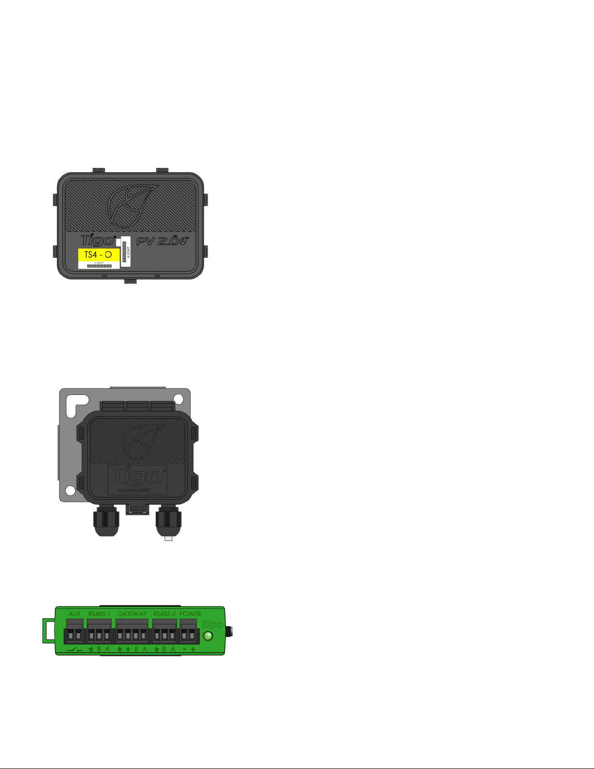
TS4
Modular smart electronics platform
Tigo Access Point
(TAP)
Wireless communication device for
monitoring and shutdown features
Cloud Connect
Advanced (CCA)
Data logger and shutdown
control
Module Level Power Electronics:
Communication Accessories:
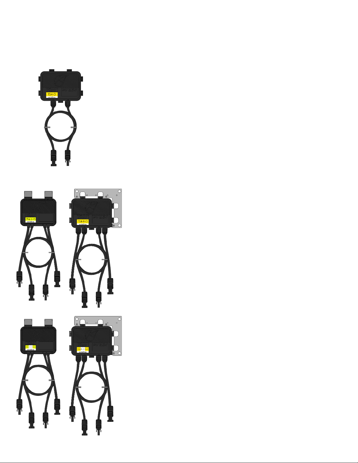
TS4 FLEX MLPE VERSIONS
5
•Bracket clips to module frame without tools
•Designed to fit two 60 cell modules in series
to one TS4-A-Duo or TS4-R-Duo
•TS4-A-Duo or TS4-R-Duo outputs are
connected in series to form a string
•No additional grounding required
•Bracket clips to module frame without tools
•TS4-R outputs are connected in series
to form a string
•No additional grounding required
• Module electronics are contained in the
junction box, installed at the PV module
factory
• Connected in series like regular modules
• No additional wiring connections to make
TS4-A-Duo, TS4-R-Duo
TS4-A, TS4-R
TS4-B
This manual suits for next models
4
Table of contents


