Fimco 1357 Series User manual

Page 1
www.fimcoindustries.com
1000 FIMCO Lane, P.O. Box 1700, North Sioux City, SD 57049
Toll Free Phone: 800-831-0027 : Toll Free Fax: 800-494-0440
[5004364 (11/22)]
1357 Series Boom Assemblies
Model: Model:
1357-12-QJD (5300699) 1357-14-QJD (5300700)
12-Row Boom Assembly 14-Row Boom Assembly
w/Quick Jet Nozzles w/Quick Jet Nozzles
• Model 1357-12-QJD Boom Assembly
(12-Row—42’ Wide)
• Model 1357-14--QJD Boom Assembly
(14-Row—48’ Wide)
OWNER’S MANUAL
General Information
Thank you for purchasing this product. The purpose of this
manual is to assist you in operating and maintaining your
Boom assembly.
BEFORE RETURNING THIS PRODUCT
FOR ANY REASON, PLEASE CALL
1-800-831-0027
MONDAY-FRIDAY, 8:00 AM TO 5:00 PM CST
If you should have a question or experience a problem with
your Fimco Industries Product: Visit our website @
www.fimcoindustries.com or call the Toll free number above. Our
technical support representatives will be happy to help you.
In most cases a customer service rep. can resolve
the problem over the phone.
To obtain prompt, efficient service, always remember to give the
following information....
• Correct Part Description and/or part number
• Model number and Serial Number
Part descriptions and numbers can be obtained from the
illustrated parts list section(s) of this manual.
Retain a copy of your receipt for your unit, as it will be required
to validate any warranty service.
Warranted against manufacturer or workmanship defects from
date of purchase with copy of receipt:
Homeowner Usage: One Year.
Commercial Usage: 90 Days.
WARNING: Cancer and Reproducve Harm.
www.P65Warnings.ca.gov
WARNING: To reduce the risk of injury, the
user must read and understand the operator’s
manual before using this product.

Page 2
Contents
Technical Specs and Warnings ...............................................21357 Series Boom Breakdown ......................................7 - 9
Assembly Instrucons ............................................................31357 Series Parts List .........................................................7
Fold Up Instrucons ...............................................................31357 (QJD) Harness Exploded View/Parts List.................10
Calibraon .........................................................................4 - 5 Warranty ..........................................................................12
Maintenance and Winter Storage ..........................................6
1357 Series Booms
Technical Specicaons All Models:
− Adjustable Spacing Nozzles
− Height Adjustment
− 4-Way Hinge for Boom Protecon
− Cross-Over Folding
− Shock Absorbers for Easy Flotaon
− Tips/Caps/Strainers are Standard (Tips: ‘AIXR’ series) (Air Inducon eXtended Range)
− Square Boom Tube Construcon
− Fits All Fimco Carriers
(**) These ps provide excellent chemical and acid resistance with an exceponally long wear life.
110° wide tapered, at spray angle with air inducon technology for beer dri management.
Compact size prevents p damage.
These TeeJet ps produce large air-lled drops through a venture air aspirator.
Approx. Weights:
Model 1357-12-QJD Boom Assembly - 434 Lbs. Model 1357-14-QJD Boom Assembly - 444 Lbs.
Always check the vehicle load rang before using a boom with sprayer, ensuring total weight is acceptable.
Do not exceed the recommended rang.
~~~~~~~~~~~~~~~~~~~~~~~~~~~~~~~~~IMPORTANT~~~~~~~~~~~~~~~~~~~~~~~~~~~~~~~~
It is VERY important to test the sprayer, aer aaching any boom with plain water before actual spraying is aempted. This will
enable you to familiarize yourself with the sprayer and check for leaks without the possibility of losing any expensive chemicals.
~~~~~~~~~~~~~~~~~~~~~~~~~~~~~~~~~~WARNING~~~~~~~~~~~~~~~~~~~~~~~~~~~~~~~~~
Read and Understand the Owner’s Manual before using this boom. Test and use in accordance to instrucons.
Read and Follow chemical label instrucons and wear protecve gear when lling, using, cleaning and
servicing the boom.
Exercise Cauon in vehicle handling when towing/hauling a lled sprayer to avoid loss of control or overturning.
Keep Sprayer and Spray materials away from other people, children and pets.
Do Not Turn on Power to the sprayer, unl ready to spray in order to avoid unintenonal spray release.
Do Not Use on steep slopes. A full sprayer could cause loss of control or overturn sprayer and vehicle.
Always operate up and down a slope, never across the face of a slope.
Keep all movement on slopes slow and gradual. Do not make sudden changes in speed, direcons or turning. Do not start or stop
suddenly when going uphill or downhill.
Stop on level ground, set the parking brake and shut o engine before leaving the operator’s posion for any reason.
Keep all parts in good condion and properly installed. Fix damaged or worn parts immediately.
Cauon should be taken when towing and/or using any sprayer. The sprayer combined with the weight distribuon, turning radius
and speed of vehicle can result in damage to vehicle, sprayer and/or boom or severe injury or death, if not used properly.
Improper use or handling of chemicals could result in serious injury or illness, or could cause damage to the environment.

Page 3
Assembly
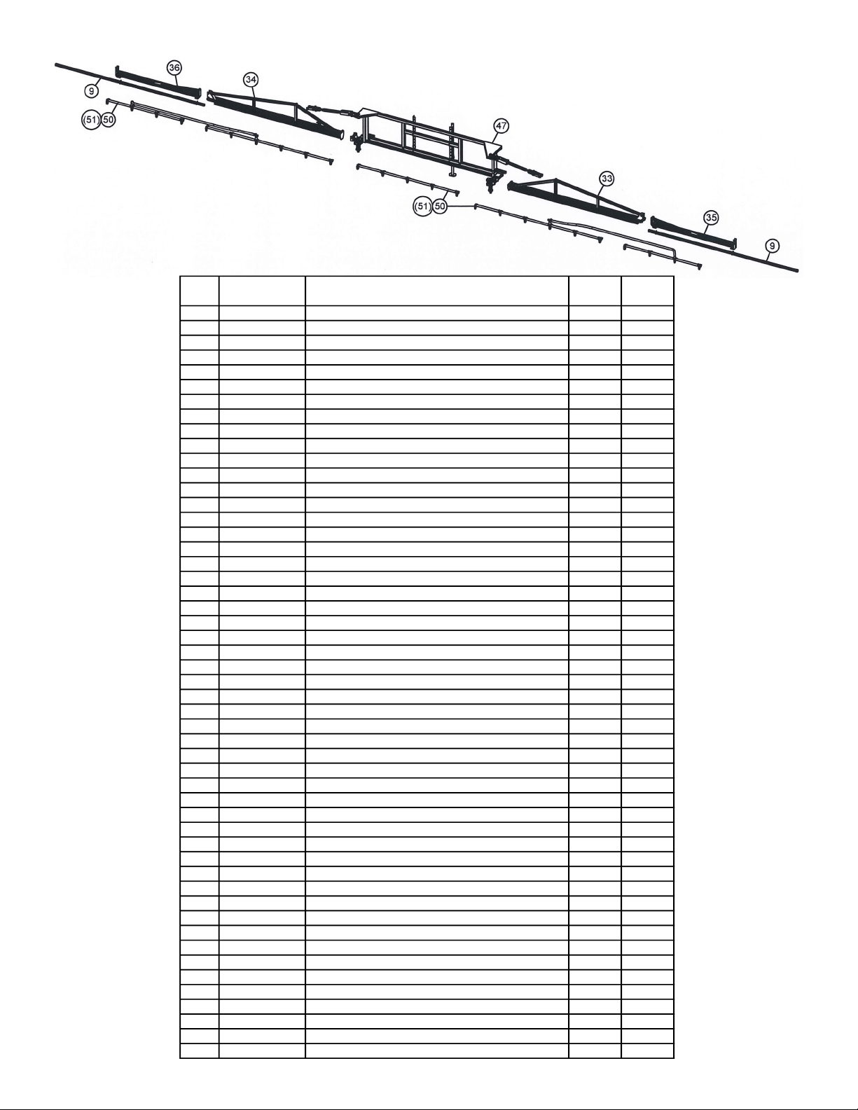
Refer to the exploded views and parts list to idenfy the parts.
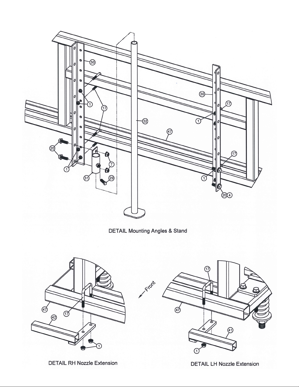
1. Mount the center secon (back rack) of the boom to the carrier or to the spring suspension boom aachment if one is being
used. Use (4) bolts and hex nuts which are aached to the upright angles. It may be necessary to loosen the bolts which hold
the upright angles to the frame in order to adjust the upright angles to match aaching members of the carrier.
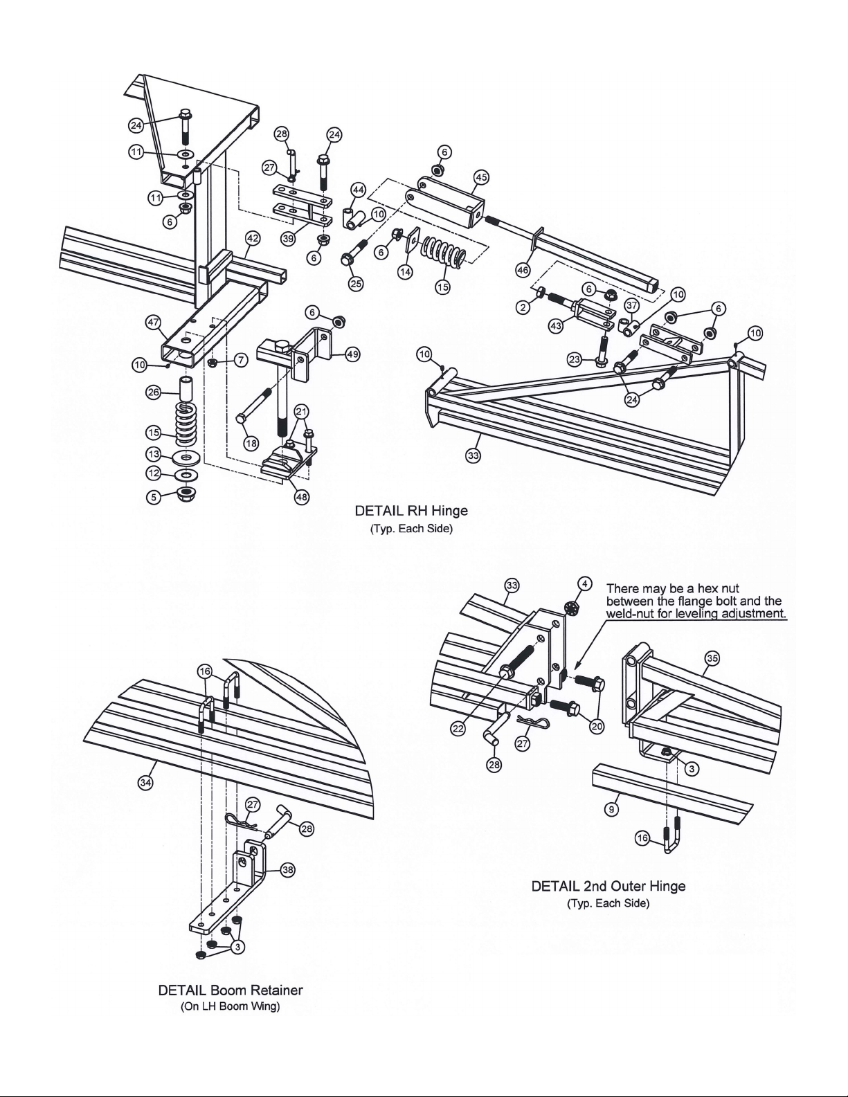
2. Aach the outer boom secons to the center frame assembly. The lower tube members of the outer booms will be oset to
the front to allow room for the hoses and nozzles, in the back. Join the outer boom secons to the center frame using (2) hex
bolts and hex ange lock nuts at the boom and use (2) hex ange bolts and hex ange lock nuts at the top of each outer sec-
on.
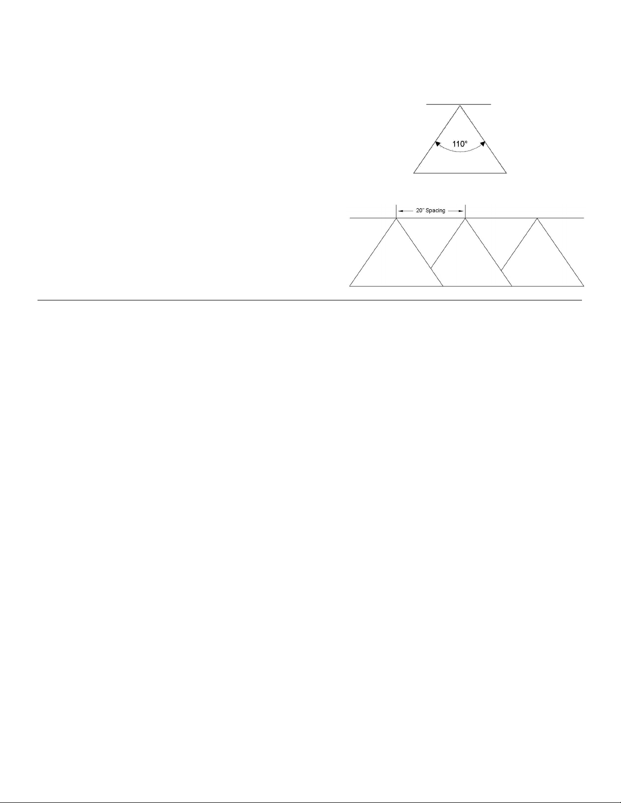
3. Aach the appropriate hose assemblies onto each of the three boom secons, the center secon has (5) nozzles with “ELL”
connectors on each end. Starng at the center, the nozzles should be placed about 20” apart. The outer boom harnesses are
made up for le and right sides when nozzles are on the back side of the outer boom tubing. Assemble the caps, ps and
strainers to each of the nozzle connectors, if not done so already.
4. Connect the feeder hoses (supply lines) from the pumping system and secure in place with hose clamps to each nozzle harness
assembly. Use nylon cable es to secure the feeder hoses to the boom so that the hoses will not snag on any object.
5. Make sure all hose clamps are ght before tesng or spraying for the rst me.
Aer assembling, sprayer will be ready to TEST w/plain water before actual use.
Fold Up Instrucons
Use cauon when folding up the booms. Do not force the pivot acon. Remember that the enre sprayer may move unless it is
anchored securely during the folding operaon.
Always begin with the le side outer boom. Remove the hairpin coer and the retainer lock pins. Fold the outer secon up and
over. Use the retainer pin and hairpin coer to secure the outer secon in place.
Remove the retainer lock pins which are located at the top ends of the center secon. These pins may be retained in the housing
aer the boom(s) have been folded back. This procedure will allow the booms to be folded without raising the ends.
Pivot the enre outer boom assembly to the rear of the sprayer and against the center frame. Use care when folding. The le outer
secon will rest on the boom carrier rack tube located on the right rear side of the center frame.
Use the same procedure to fold up the right outer boom assembly. This outer secon will rest on the boom retainer, located on the
le wing boom. Use the retainer lock pin to secure the right wing boom in place.
If it is necessary to ghten the spring tension, pivot the outer boom 90° before ghtening the tension. Do not ghten the tension
any more than can be done in this posion, otherwise the boom will not pivot out of the receiver.
Tesng the Sprayer
NOTE: It is VERY important to test your sprayer with plain water before actual spraying is aempted. This will enable you to
familiarize yourself with the sprayer and boom and to check for leaks, without the possibility of losing any expensive chemicals.
Follow the instrucons in your sprayer manual for tesng your sprayer.
Always have the pressure line open to the ps so that the air which may be trapped in the line will be forced (or purged) out. Start
the tractor PTO. Check the enre system for leaks. Once the pump is primed, the pressure may be increased by turning the handle
of the pressure relief valve. Keep the pressure line open to the ps when seng the pressure. Set the pressure and then lock the
relief valve handle in place. Pressure will increase when the pressure line valve is closed and then return to the preset pressure
when the valve is opened again.
The bypass valve is the “pressure control” for the enre plumbing system. The more the valve is open, the lower your line pres-
sure. Almost fully closed provides maximum pressure to your boom and/or handgun. NEVER run your system with this valve 100%
closed.
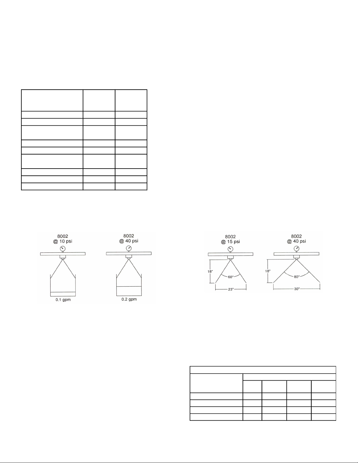
During the tesng period, be sure to observe the spray paern given by the spray nozzles. If there is any paern distoron, it will
be necessary to remove and clean the aected ps.
Cauon: Never use a metal object or other sharp item for cleaning a nozzle p. It is beer to use a nozzle brush (NOT wire brush)
or compressed air for p cleaning.
Condions of weather and terrain must be considered when seng the sprayer. Do not spray on windy days. Protecve clothing
must be worn in some cases
Be sure to read the chemical label(s) before applicaon!

Page 4
Pressure
(psi)
Capacity
(GPM)
1
MPH
2
MPH
3
MPH
4
MPH
5
MPH
6
MPH
8
MPH
15 .18 53.6 26.8 17.8 13.4 10.7 8.9 6.7
20 .21 62.4 31.2 20.8 15.6 12.5 10.4 7.8
30 .26 77.2 38.6 25.8 19.3 15.4 12.9 9.7
40 .30 88.0 44.0 29.8 22.0 17.8 14.9 11.1
15 .18 .61 .41 .31 .24
20 .21 .71 .48 .36 .29
30 .26 .88 .59 .44 .35
40 .30 1.0 .68 .51 .41
Gallons Per
Acre
Based on Water
Gallons Per
1000 Sq. Ft.
Based on Water
AIXR11003VP Spray Tip Rate Chart (20" Spacing)
100 Ft. 200 Ft. 300 Ft.
1.0 68 sec. 136 205
2.0 34 68 102
3.0 23 45 68
4.0 17 34 51
5.0 14 27 41
6.0 11 23 34
7.0 9.7 19 29
8.0 8.5 17 26
Speed Chart
Time Required in seconds
to travel a distance of
Speed in M.P.H.
(Miles Per Hour)
Calibraon
Chemical labels may show applicaon rates in gallons per acre, gallons per 1000 square feet or gallons per 100 square feet. You will
note that the p chart shows 2 of these rang systems.
Once you know how much you are going to spray, then determine (from the p chart) the spraying pressure (PSI) and the spraying
speed (MPH).
Determining the proper speed of the pulling vehicle can be done by marking o 100, 200 and 300 feet. The speed chart indicates
the number of seconds it takes to travel the distances. Adjust the throle unl you travel the distances in the number of seconds
indicated by the speed chart. Once you have reached the throle seng needed, mark the throle locaon, so you can stop and
go again, returning to the same speed.
Add water and proper amount of chemical to the tank and drive to the starng place for spraying.
Tip Selecon
Important Note:
The ps supplied as standard with this boom assembly are number AIXR11003VP ps, when you refer to the spray p rate chart
found in this owner’s manual, you will note that they have a GPA range of 10.7 to 17.8 GPA (Gallons Per Acre). This is tabulated at
5 MPH and from 15-40 psi and 20” nozzle spacing. These rates are based on water. Please read this p selecon secon carefully
before aempng to operate your boom assembly.
The selecon of proper ps for the boom is determined by the gallon per acre (GPA) requirement, which is specied on the chemi-
cal label. The following characteriscs also have a determining factor and must be considered:
1. Speed of spraying (MPH)
2. Boom nozzle spacing (specied in inches)
3. Soluon weight and conversion factor (CF)
4. Gallons of soluon to be sprayed per acre
5. Spraying pressure
Useful Formulas:
GPM—Gallons Per Minute
GPA—Gallons Per Acre
MPH—Miles Per Hour
Nozzle Spacing
If the nozzle spacing on your boom is dierent from those tabulated, mulply the tabulated GPA coverage by one of the following
actors.
Other Spacing 8" 10" 12" 14" 16" 18" 22" 24" 30"
Conversion
Factor
2.5 21.67 1.43 1.25 1.11 .91 .83 .66
Other Spacing 26" 28" 32" 34" 36" 38" 40" 42" 44"
Conversion
Factor
1.15 1.07 .94 .88 .83 .79 .75 .71 .68
Other Spacing 28" 30" 32" 34" 36" 38" 42" 44" 48"
Conversion
Factor
1.43 1.33 1.25 1.18 1.11 1.05 .95 .91 .83
Where Tables are Based on 20" Nozzle Spacing
Where Tables are Based on 30" Nozzle Spacing
Where Tables are Based on 40" Nozzle Spacing

Page 5
Spraying Soluons Other Than Water
Since all the tabulaons are based on spraying water, which weights 8.34 lbs. per USA gallon, conversion factors must be used
when spraying soluons which are heavier or lighter than water. To determine the proper size nozzle for the soluon to be
sprayed, rst mulply the desired GPM or GPA of soluon by the rate conversion factor. Then use the new converted GPM or GPA
rate to select the proper size nozzle.
Example: Desired applicaon rate is 20 GPA of 28% Nitrogen. Determine the correct nozzle size as follows:
GPA (Soluon) x Conversion Factor = GPA
20 GPA (28%) x 1.13 = 22.6 GPA (Water)
The applicator should choose a nozzle size that will supply 22.6 GPA of water at the desired pressure.
Miscellaneous Conversion Factors
One Acre = 43,560 square feet = 0.405 Hectacre
One Hectacre = 2.471 Acres
One Gallon Per Acre = 9.35 Liters Per Hectacre
One Mile = 5280 Feet = 1610 Meters = 1.61 Kilometers
One Gallon = 128 Fluid Ounces = 8 Pints = 4 Quarts = 3.79
Liters = 0.83 Imperial Gallons
One Pound Per Square Inch = 0.069 bar. = 6.895 Kilopascals
One Mile Per Hour = 1.609 Kilometers Per Hour
Flow Rate
Nozzle ow rate varies with spraying pressure. In general, the relaonship between GPM and pressure is as follows:
This equaon is explained by the illustraon below. Simply stated, to double the ow through a nozzle, the pressure be increased
four mes
Eect of Pressure on Volume Eect of Pressure on Spray Angle
Higher pressure not only increases the ow rate of the nozzle, but it also inuences the droplet size and the rate of orice wear. As
pressure is increased, the droplet size decreases and the rate of orice wear is increased.
The values given in the tabulaon secon of this owner’s manual indicate the most commonly used pressure ranges for the associ-
ated spray ps.
Spray Angle and Coverage
Depending on the nozzle type and size, the operang pressure can have a signicant eect on spray angle and quality of spray
distribuon. As shown above for an 8002 at spray p, as an example, lowering the pressure results in a smaller spray angle and a
signicant reducon in spray coverage.
Tabulaons for spray ps shown in this owner’s manual are based
on spraying water. Generally, liquids more viscous than water form
relavely smaller spray angles. Whereas, liquids with surface ten-
sions lower than water will produce wider spray angles. In situa-
ons where the uniformity of spray distribuon is important, be
careful to operate your spray ps within the proper pressure
range.
NOTE: Suggested minimum spray heights for broadcast spraying
are based upon nozzles spraying water at the rated spray angle.
Weight of Solution
Specific
Gravity
Conversion
Factors
7.0 lbs. per gallon .84 .92
8.0 lbs. per gallon .96 .98
8.345 lbs. per gallon
(Water)
1.00 1.00
9.0 lbs. per gallon 1.08 1.04
10.0 lbs. per gallon 1.20 1.10
10.66 lbs. per gallon
(28% Nitrogen)
1.28 1.13
11.0 lbs. per gallon 1.32 1.15
12.0 lbs. per gallon 1.44 1.20
14.0 lbs. per gallon 1.68 1.30
Spray
Angle
20"
Spacing
30"
Spacing
40"
Spacing
TeeJet (Flat Spray) 65° 22"-24" 33"-35" NR*
TeeJet (XR TeeJet) 80° 17"-19" 26"-28" NR*
TeeJet (XR TeeJet) 110° 12"-14" 16"-18" NR*
FloodJet 120°*** *** ***
* Not Recommended
*** Wide Angle Spray Tip is influenced by nozzle orientation.
The critical factor is to achieve a double spray patter overlap.
Suggested Minimum Spray Heights
Nozzle Type
Nozzle Height

Page 6
Aer Spraying
Aer use, ll your sprayer tank part way with water. Start the sprayer and allow the clear water to be pumped through the plumb-
ing system and out through the spray nozzles.
Rell the tank about half full with plain water and use FIMCO Tank Neutralizer and Cleaner and repeat cleaning instrucons above.
Flush the enre sprayer with the neutralizing/cleaning agent, then ush out one more me with plain water. Follow the chemical
manufacturer’s disposal instrucons of all wash or rinsing water. For the boom, remove the ps and screens from the nozzle as-
semblies. Wash these items out thoroughly. Blow the orice clean and dry. If the orice remains clogged, clean it with a ne bristle
(NOT WIRE) brush or with a toothpick. Do not damage the orice. Water rinse and dry the ps before storing.
Winterizing your Sprayer
It is essenal that you winterize your sprayer to avoid damage and to allow for opmal performance. The winterizaon process
should be undertaken before freezing condions and/or aer each season of use.
Drain all water out of your sprayer, paying special aenon to the pump, handgun and valve(s). These items are especially prone
to damage from chemicals and freezing weather.
The sprayer should be winterized before storage by pumping a soluon of automove anfreeze (containing a rust inhibitor)
through the enre plumbing system. This anfreeze soluon should remain in the plumbing system during the winter months.
1. Verify that the tank is empty and rinsed out. Pour 1-2 gallons of anfreeze into the tank.
Using a soluon of automove anfreeze (containing a rust inhibitor).
2. Engage the pump and spray with the boom and spray gun (if applicable). Make sure that the anfreeze has been pumped
through the enre system, including all spray nozzles.
3. Before spraying in the spring, it is recommended to ush the sprayer with fresh water to cleanse it of the anfreeze and any
other buildup. It would also be benecial to do a thorough inspecon of all sprayer components before spraying.
Proper care and maintenance will prolong the life of your sprayer.
The AIXR TeeJet Flat Spray Tip oers the benets of obtaining excellent dri resistance without compromising spray coverage. Tips
producing very coarse droplets do minimize dri but do not provide the same surface coverage as ps that produce smaller drop-
lets. In some applicaons, inadequate coverage decreases the eecveness of the applied chemicals.
Based on the minimum overlap required to obtain uniform distribuon with
110° ps and 20” spacing.
Suggested Minimum Spray Height: 16”-18” above what is being sprayed
(to plant, not ground).
Opmum Spray Height: 20”
• 110° wide, tapered at spray angle with air inducon technology
for beer dri management
• Made of 2-piece UHMWPE polymer construcon which provides
excellent chemical resistance, including acids, as well as excep-
onal wear life
• Compact size to prevent p damage
• Excellent for systemic products and dri management

Page 7
1357-12-QJD (5300699)
1357-14-QJD (5300700)
Ref. # Part # Description
1357-12
Qty.
1357-14
Qty.
15006259 3/8"-16nc Hex Flanged Whiz Nut, Grade 5 12 12
25006260 3/4"-10 Hex Jam Nut 2 2
35006307 5/16"-18nc Hex Flanged Whiz Nut, Grade 5 12 12
45006337 1/2-13 Hex Whiz (Flange) Locknut 4 4
55006363 1"-8nc Hex Flanged Toplock Nut, Grade 8 2 2
65006364 5/8"-11nc Hex Flanged Toplock Nut, Grade 8 16 16
75006365 1/2"-13nc Hex Flanged Toplock Nut, Grade 8 6 6
85006366 3/8"-16nc Hex Flanged Toplock Nut, Grade 8 2 2
95009228-BLK Boom Tube (120") 2 2
10 5012003 Grease Zerk, 3/16" Straight Drive 16 16
11 5016053 Flatwasher, 5/8" 4 4
12 5016198 Thrust Washer (1") 2 2
13 5016200-BLK Spring Retainer Washer 2 2
14 5016252-BLK Spring Washer 2 2
15 5019157-BLK Compression Spring 4 4
16 5034159 Square U-Bolt, 5/16" x 1-5/16" x 1-7/8" 6 6
17 5034188 Square U-Bolt, 3/8" Dia. x 2-1/8" x 2-7/8" 6 6
18 5034222 H.H.C.S. Flanged 5/8"-11 x 6-1/2" 2 2
19 5034666 H.H.C.S. Flanged 3/8"-16nc x 2-1/4" 2 2
20 5034692 H.H.C.S. Flanged 1/2"-13nc x 1-1/2" 8 8
21 5034699 H.H.C.S. Flanged 1/2"-13nc x 3-3/4" 4 4
22 5034700 H.H.C.S. Flanged 1/2"-13nc x 3-1/2" 2 2
23 5034724 H.H.C.S. Flanged 5/8"-11nc x 3" 2 2
24 5034726 H.H.C.S. Flanged 5/8"-11nc x 3-1/2" 8 8
25 5034728 H.H.C.S. Flanged 5/8"-11nc x 4" 2 2
26 5077036-BLK Spring Guide 2 2
27 5101065 #211 Hitch Pin Clip (Zinc Plated) 5 5
28 5101202 Bent Clevis Pin (1/2" Dia.) 5 5
29 5117104 1/2"-13 x 1-1/2" Square Head Set Screw 1 1
30 5144030-BLK Upright 2 2
31 5271998-BLK Stand Sleeve Weldment 1 1
32 5271999-BLK Stand Weldment 1 1
33 5272624-BLK Wing Boom Weldment (RH) 1 1
34 5272625-BLK Wing Boom Weldment (LH) 1 1
35 5272626-BLK Outer Boom Weldment (RH) 1 1
36 5272627-BLK Outer Boom Weldment (LH) 1 1
37 5272630-BLK Trunion Weldment 2 2
38 5272632-BLK Boom Retainer Weldment 1 1
39 5272633-BLK Pivot Arm Weldment 2 2
40 5272634-BLK
Attaching Bracket Weldment 2 2
41 5272635-BLK Hinge Nozzle Tube Weldment (LH) 1 1
42 5272636-BLK Hinge Nozzle Tube Weldment (RH) 1 1
43 5272637-BLK Adjustable Clvis Weldment 2 2
44 5273118-BLK Boom Support Trunion Weldment 2 2
45 5273119-BLK Spring Bracket Weldment 2 2
46 5273120-BLK
Boom Support Weldment 2 2
47 5273733-BLK
Center Frame Weldment 1 1
48 5273734-BLK Lower Pivot Clevis Weldment 2 2
49 5273735-BLK Upper Pivot Clevis Weldment 2 2
50 5300358
Complete 1357-12-QJD Nozzle Harness 1 -
51 5300359 Complete 1357-14-QJD Nozzle Harness - 1

Page 8
1357 Series Boom Assembly Details
Model 1357-12-QJD Boom Assembly (12-Row, 5-Secon,
42’ Wide) (25 Nozzles)
Model 1357-14--QJD Boom Assembly (14-Row, 5-Secon,
48’ Wide) (29 Nozzles)

Page 9
1357 Series Boom Assembly Details

Page 10
Center
1357-12 RH
1357-14 LH
1357-12 RH
Ref. # Part # Description 1357-12-QJD 1357-14-QJD
15020287 Hose, 3/4"-1 BRD. x 19" 20 24
25051024 Hose Clamp, 3/4" 48 52
35020150 Hose, 3/4"-1 BRD. x 108" 2 2
45020351 Hose, 3/4"-1 BRD. x 3" 2 2
55086030 Poly Hose Barb, 3/4" x 3/4" x 3/4" 2 2
65056066 Single Hose Shank, 3/4" Elbow 10 10
75056068 Double Hose Shank, 3/4" TEE 10 14
85056070 Triple Hose Shank, 3/4" CROSS 5 5
95116019 Strainer, 50 Mesh (Blue) 25 29
10 5016157 Seat Washer (QJ Caps) 25 29
11 AIXR11003VP Air-Induction XR Flat Spray Tip 25 29
12 5046217 QJ Cap Only (Blue) 25 29
13 5272165 Vari-Quick Clamp (1 1/4" Sq. Tube) 25 29
Typical Nozzle Assembly Conguraons
Elbow Tee Cross
#5277722 #5277723 #5277724
Assemblies consist of “Elbow”, “Tee” & “Cross” style nozzles.
Assemblies include: Nozzle Body, Strainer, Seat Washer,
AIXR11003VP Nozzles & Nozzle Cap
NOTES:
All hoses that are not called out, will be hose #5020287 (Item 1)
All hose clamps (2 per hose) are #5051024 (Item 2)
Detail
Line In
ELBOW TEE TEE CROSS TEE ELBOW ELBOW TEE CROSS TEE TEE ELBOW
ELBOW TEE TEE CROSS TEE ELBOW ELBOW TEE CROSS ELBOW
ELBOW CROSS TEE ELBOW ELBOW TEE CROSS TEE TEE ELBOW
ELBOW TEE CROSS TEE ELBOW
Complete Nozzle Harness Assemblies (1357-12-QJD & 1357-14-QJD)
1357-12-QJD
12-Row, 5-Section
(42') Boom Assembly
25 Nozzles
1357-14-QJD
14-Row, 5-Section
(48') Boom Assembly
29 Nozzles
Center Nozzle Harness 5277882
LH Nozzle Harness 5277883
RH Nozzle Harness 5277884
Center Nozzle Harness 5277882
LH Nozzle Harness 5277885
RH Nozzle Harness 5277886
1357-12-QJD
1357-14-QJD
1357-12 LH

Page 11
NOTES:

Page 12
LIMITED WARRANTY FOR NEW FIMCO, INC.
WHO MAY USE THIS LIMITED WARRANTY. This limited warranty (the “Limited Warranty”) is provided by Fimco, Inc. to the original purchaser
(“you”) of the Equipment (as dened below) from Fimco, Inc. or one of Fimco, Inc.’s authorized dealers. This Limited Warranty does not apply to
any subsequent owner or other transferee of the Equipment. THIS LIMITED WARRANTY GIVES YOU SPECIFIC LEGAL RIGHTS, AND YOU MAY ALSO
HAVE OTHER RIGHTS WHICH VARY FROM STATE TO STATE.
WHAT THIS LIMITED WARRANTY COVERS AND FOR HOW LONG. Fimco, Inc. warrants that any registered new Equipment will be free from de-
fects in material and workmanship for a period of one (1) year (homeowner), 90 days (commercial user), aer delivery of the Equipment to you
(the “Warranty Period”). The Warranty Period is not extended if Fimco, Inc. repairs or replaces the Equipment.
WHAT IS NOT COVERED BY THIS LIMITED WARRANTY. This Limited Warranty does not apply to: (1) used Equipment; (2) any Equipment that has
been altered, changed, repaired or treated since its delivery to you, other than by Fimco, Inc. or its authorized dealers; (3) damage or deprecia-
on due to normal wear and tear; (4) defects or damage due to failure to follow Fimco, Inc.’s operator’s manual, specicaons or other wrien
instrucons, or improper storage, operaon, maintenance, applicaon or installaon of parts; (5) defects or damage due to misuse, accident or
neglect, “acts of God” or other events beyond Fimco, Inc.’s reasonable control; (6) accessories, aachments, tools or parts that were not manu-
factured by Fimco, Inc., whether or not sold or operated with the Equipment; or (7) rubber parts, such as res, hoses and grommets.
HOW TO OBTAIN WARRANTY SERVICE. To obtain warranty service under this Limited Warranty, you must (1) provide wrien noce to Fimco,
Inc. of the defect during the Warranty Period and within thirty (30) days aer the defect becomes apparent or the repair becomes necessary, at
the following address: Fimco, Inc., 1000 Fimco Lane, North Sioux City, SD 57049; and (2) make the Equipment available to Fimco, Inc. or an
authorized dealer within a reasonable period of me. For more informaon about this Limited Warranty, please call: 800-831-0027
WHAT REMEDIES ARE AVAILABLE UNDER THIS LIMITED WARRANTY. If the condions set forth above are fullled and the Equipment or any part
thereof is found to be defecve, Fimco, Inc. shall, at its own cost, and at its opon, either repair or replace the defecve Equipment or part.
Fimco, Inc. will pay for shipping and handling fees to return the repaired or replacement Equipment or part to you.
LIMITATION OF IMPLIED WARRANTIES AND OTHER REMEDIES. THE REMEDIES DESCRIBED ABOVE ARE YOUR SOLE AND EXCLUSIVE REMEDIES,
AND FIMCO, INC.’S SOLE LIABILITY, FOR ANY BREACH OF THIS LIMITED WARRANTY. TO THE EXTENT APPLICABLE, ANY IMPLIED WARRANTIES,
INCLUDING, WITHOUT LIMITATION, THE IMPLIED WARRANTIES OF MERCHANTABILITY AND FITNESS FOR A PARTICULAR PURPOSE, SHALL BE LIM-
ITED IN DURATION TO THE WARRANTY PERIOD, AND THE REMEDIES AVAILABLE FOR BREACH THEREOF SHALL BE LIMITED TO THE REMEDIES
AVAILABLE UNDER THIS EXPRESS LIMITED WARRANTY. SOME STATES DO NOT ALLOW LIMITATIONS ON HOW LONG AN IMPLIED WARRANTY
LASTS, SO THE ABOVE LIMITATION MAY NOT APPLY TO YOU. IN NO EVENT SHALL FIMCO, INC.’S LIABILITY UNDER THIS LIMITED WARRANTY EX-
CEED THE ACTUAL AMOUNT PAID BY YOU FOR THE DEFECTIVE EQUIPMENT, NOR SHALL FIMCO, INC. BE LIABLE, UNDER ANY CIRCUMSTANCES,
FOR ANY CONSEQUENTIAL, INCIDENTAL, SPECIAL OR PUNITIVE DAMAGES OR LOSSES, WHETHER DIRECT OR INDIRECT. SOME STATES DO NOT
ALLOW THE EXCLUSION OR LIMITATION OF INCIDENTAL OR CONSEQUENTIAL DAMAGES, SO THE ABOVE LIMITATION OR EXCLUSION MAY NOT
APPLY TO YOU.
Warranty Info
This manual suits for next models
4
Table of contents
Other Fimco Industrial Equipment manuals
Popular Industrial Equipment manuals by other brands

ABB
ABB HT847245 Operation manual

Edge Technologies
Edge Technologies Patriot Series Operation manual

Polaris
Polaris FlexoPlast instruction manual

Mirion Technologies
Mirion Technologies CheckPoint:Gate RTM690 Technical handbook

ABB
ABB HT565236 Operation manual

Graco
Graco Therm-O-Flow 5 918343 Instructions-parts list

Milnor
Milnor 7676TG1L/R Installation

ABB
ABB HT598351 Operation manual

Graco
Graco InvisiPac GS35 Plug-Free Instructions-parts list

Hypertherm
Hypertherm SENSOR OHC manual

Rohm
Rohm DURO-A Translation of the original operating manual

Fisher Bioblock Scientific
Fisher Bioblock Scientific 8 970 630 User information