finder 7M.38.8.400.0112 User manual

USER’S MANUAL 7M
SERIES OF THREEPHASE METERS 7M.38.8.400.XXXX:
7M.38.8.400.0112
7M.38.8.400.0212
7M.38.8.400.0312

User’s Manual 7M 1
THREEPHASE ELECTRICAL ENERGY METER
USER AND INSTALLATION MANUAL

User’s Manual 7M 2
SECURITY ADVICES AND WARNINGS
Please read this chapter carefully and examine the equipment carefully for potential damages which might arise during
transport and to become familiar with it before continue to install, energize and work with a three-phase energy meter
7M.38.8.400.xxxx.
This chapter deals with important information and warnings that should be considered for safe installation and handling
with a device in order to assure its correct use and continuous operation.
Everyone using the product should become familiar with the contents of chapter »Security Advices and Warnings«.
If equipment is used in a manner not specied by the manufacturer, the protection provided by the equipment may be
impaired.
PLEASE NOTE
This booklet contains instructions for installation and use of three-phase energy meter 7M.38.8.400.xxxx.
Installation and use of a device also includes handling with dangerous currents and voltages therefore should be installed,
operated, serviced and maintained by qualied personnel only. FINDER S.p.A assumes no responsibility in connection with
installation and use of the product.
If there is any doubt regarding installation and use of the system in which the device is used for measuring or supervision,
please contact a person who is responsible for installation of such system.
BEFORE SWITCHING THE DEVICE ON
Check the following before switching on the device:
• Nominal voltage
• Terminals integrity
• Protection fuse for voltage inputs (recommended maximal external fuse size is 80 A)
• External switch or circuit breaker must be included in the installation for disconnection of the devices’power supply.
It must be suitably located and properly marked for reliable disconnection of the device when needed
• Proper connection and voltage level of I/O module

User’s Manual 7M 3
USED SYMBOLS ON DEVICES’HOUSING AND LABELS
SYMBOL EXPLANATION
Three-phase 4-wire connection (3L+N)
Three-phase 3-wire 3 system connection (3L)
Three-phase 3-wire 2 system connection (3L-2I Aron connection)
Single-phase connection (L+N).
!WARNING
Indicates situations where careful reading of this manual is required and following
requested steps to avoid potential injury is advised
Double insulation in compliance with the EN 61010−1: 2010 standard
NFC communication
IR - infrared (optical) communication

User’s Manual 7M 4
DISPOSAL
It is strongly recommended that electrical and electronic equipment (WEEE) is not deposit as municipal waste.
The manufacturer or provider shall take waste electrical and electronic equipment free of charge.
The complete procedure after lifetime should comply with the Directive 2002/96/EC about restriction on the use of certain
hazardous substances in electrical and electronic equipment.
SYMBOL EXPLANATION
Modbus communication
MBus communication
Compliance of the product with directive 2002/96/EC, as rst priority, the prevention
of waste electrical and electronic equipment (WEEE), and in addition, the reuse,
recycling and other forms of recovery of such wastes so as to reduce the disposal
of waste. It also seeks to improve the environmental performance of all operators
involved in the life cycle of electrical and electronic equipment
Compliance of the product with European CE directives

User’s Manual 7M 5
TABLE OF CONTENTS
BASIC DESCRIPTION AND OPERATION page - 6
INTRODUCTION page - 6
DESCRIPTION OF THE DEVICE page - 6
THREEPHASE ENERGY METERS APPLICATION page - 7
MAIN FEATURES page - 7
TYPE DIFFERENCES page - 8
CONNECTION page - 9
MOUNTING page - 9
ELECTRICAL CONNECTION page - 10
FIRST STEPS page - 14
KEYBOARD NAVIGATION page - 14
LCD USER INTERFACE page - 14
CALIBRATION AND SETTING PARAMETERS page - 27
FREEZE COUNTERS page - 27
TECHNICAL DATA page - 29
ACCURACY page - 29
MECHANICAL CHARACTERISTICS OF INPUT page - 29
ELECTRICAL CHARACTERISTICS OF INPUT page - 30
SAFETY AND AMBIENT CONDITIONS page - 31
EU DIRECTIVES CONFORMITY page - 32
DIMENSIONS page - 32
ABBREVIATION/GLOSSARY page - 33
APPENDICES page - 34
APPENDIX A: MODBUS COMMUNICATION PROTOCOL page - 34
APPENDIX B: MBUS page - 58
APPENDIX C: EQUATIONS page - 59

User’s Manual 7M 6
BASIC DESCRIPTION AND OPERATION
The following chapter presents basic information about a three-phase energy meter 7M.38.8.400.xxxx required to understand
its purpose, applicability and basic features connected to its operation. In this chapter you will nd:
• INTRODUCTION
• DESCRIPTION OF THE DEVICE
• THREEPHASE ENERGY METERS APPLICATION
• MAIN FEATURES
• TYPE DIFFERENCES
INTRODUCTION
Regarding the options of a three phase energy meter, dierent chapters should be considered since it might vary in functionality.
TABLES
Supported functions and measurements are listed in tables. Symbols in tables indicate support of enabled functions for
dierent connection schemes. Additionally a legend is placed below table of used symbols. Meaning of symbols is:
Function is supported
Function is not supported
Symbol meaning varies and is described in the legend below the table
DESCRIPTION OF THE DEVICE
The three-phase energy meters 7M.38.8.400.xxxx are intended for energy measurements in three-phase electrical power
network and can be used in residential, industrial and utility applications. Meters measure energy directly in 3-wire and
4-wire networks according to the principle of fast sampling of voltage and current signals.
A built-in microprocessor calculates active/reactive/apparent power and energy, current, voltage, frequency, power factor,
power angle and frequency (for each phase and total sum) from the measured signals. This smart meter can also perform
basic harmonic analysis (THDU, THDI). This enables quick overview of harmonic distortion either coming from a network
or generated by the load. Microprocessor also controls LCD, LED, IR communication and optional extensions.
A capacitive touch button on the front of the energy meter enables access to switch between measurements and settings
in the menu. Connecting terminals can be sealed up against non-authorised access with protection covers.
The meters are built to be fastened according to EN 60715 standard.
Figure 1: Appearance of three-phase electric energy meter 7M.38.8.400.xxxx
1 Current terminals – to load
2 AUX terminals (options):
• RS485 (MODBus)
• M-BUS
• PULSE INPUT AND OUTPUT (S01,2)
3 NFC
4 Information display
5 DIN-Rail tting
6 IR communication port – ON SIDE
7 LED indicator
8 Cap touch
9 Tari clock input
10 Neutral input
11 Current terminal – source (max 80 A)
LCD Display type: Matrix (128 x 64)
Illumination: white (normal operation)
red (alarm indication)
LED Colour: red
Pulse rate: 1000 imp/kWh
LED on: no load indication

User’s Manual 7M 7
THREEPHASE ENERGY METERS APPLICATION
Energy meters have built-in optical (IR) communication port on the side.
It can be used for controlling Bistable switch – or in combination with SG smart gateway.
It can be used for direct communication with a PC to change settings of devices without any communication installed.
Optional the meter can be equipped with the following communications:
• RS485 serial communication with the MODBUS protocol
• M-BUS serial communication
Communication modules enables data transmission and thus connection of the measuring places into the network for the
control and management with energy.
Besides of communication modules, there are also tari input and built-in pulse output.
Tari input provides measurement of two taris for selected energy registers.
Pulse output S01,2 is sending data to the devices for checking and monitoring consumed energy.
Energy meters are equipped with NFC communication for easy setting and downloading data via mobile app.
NFC communication is implemented for parametrization as well as for reading data (e.g. counters, measurements, etc.)
from the smart meter. Special application available from our internet site has to be used to perform such operations.
MAIN FEATURES
• Three-phase direct connected DIN-rail mounting meters up to maximum current 80 A (Imax)
• MID approval
• Class 1 for active energy according to EN 62053-21 and B according to EN 50470-3
• Class 2 for reactive energy according to IEC 62053-23
• Bidirectional energy measurement (import/export)
• Temperature range climatic condition as indoor meter according EN 50470
• Display segment Matrix LCD
• Multifunctional front red LED
• IR serial communication
• Measurement of:
o power (active, reactive, apparent) and energy (each phase and total)
o voltage (each phase)
o current (each phase)
o phase to phase voltage
o phase to phase angle
o frequency
o power factor (each phase and total)
o power angle (each phase and total)
o active tari (option)
o THD of voltage
o THD of current
• 2nd multifunction pulse output (valid only for 7M.38.8.400.0112)
• RS485 Serial communication (valid only for 7M.38.8.400.0212)
• NFC (option) enables an easy setting and downloading meter data via mobile app
• M-bus Serial communication (valid only for 7M.38.8.400.0312)
• Tari input (230 V AC)
• Tari management (up to 6 taris manageable via communication)
• –25°C - 70°C ambient operation temperature
• Limit control (Alarm) function can give info about exceeded conditions and trigger switch through IR communication
• 3-DIN rail width mounting according to EN 60715
• Sealable terminal cover

User’s Manual 7M 8
TYPE DIFFERENCES
Dierent type dier on functionality and equipment as shown in the following table.
General hardware features 7M.38.8.400.0112 7M.38.8.400.0212 7M.38.8.400.0312
MID approval
Pulse output S01
Pulse output S02– –
Tari input
70°C display
Infrared (optical) communication - IR
MODBUS comm. Protocol RS485 – –
General software features 7M.38.8.400.0112 7M.38.8.400.0312 7M.38.8.400.0212
MODBUS comm. Protocol (IR)
M-bus serial comm. – –
NFC communication
Table 1: General hardware and software features of dierent types of meters

User’s Manual 7M 9
CONNECTION
This chapter deals with the instructions for three-phase electrical energy meter 7M.38.8.400.xxxx connection.
Both the use and connection of the device includes handling with dangerous currents and voltages.
Connection shall therefore be performed ONLY by a qualied person using an appropriate equipment. FINDER S.p.A, does
not take any responsibility regarding the use and connection.
If any doubt occurs regarding connection and use in the system which device is intended for, please contact a person who
is responsible for such installations.
In this chapter you will nd:
• MOUNTING
• ELECTRICAL CONNECTION
MOUNTING
Threee-phase electrical energy meter 7M.38.8.400.xxxx is intended for DIN-rail mounting.
In case of using the stranded wire, the ferrule must be attached before the mounting.
Figure 2: Dimensional drawing and rear connection terminals position

User’s Manual 7M 10
ELECTRICAL CONNECTION
WARNING
Wrong or incomplete connection of voltage or other terminals can cause non-operation or damage to the device.
Installation must be carried out and inspected by a specialist or under his supervision.
When working on the meter, switch o the mains voltage! It is recommended to use 3x80 A fuse for the line protection.
Meter is used for direct connection into the three-phase four-wire or three-wire networks.
It can be used also in single-phase network, connected in the phase L3. Three-wire 2 system connection network measures
only phase to phase values (phase values are not available).
After electrical installation for MID approved meters the installation should be also set and conrmed in software.
Until installation conrmation warning Installation not set is displayed on LCD. For installation setting see item 3.2.1.
PLEASE NOTE
Setting of installation (see paragraph 3.2.1.) can be done just once, so take care to conrm the connection which ts
the required connection and required use.
Recommended installation:
1 Mounting to DIN rail according to DIN EN60715
2 Power contacts:
• Power contacts capacity 2.5 mm2– 25 mm2
• Connection screws M5
• Max torque 3.5 Nm
3 Auxiliary terminals:
• Auxiliary terminals contact capacity 0.05 mm2– 1.5 mm2
• Auxiliary terminals screws M3
• Max torque 0.6 Nm
Mark Meaning
L1,2,3Line input
N Neutral input
Table 2: Marks used on wire connection diagrams
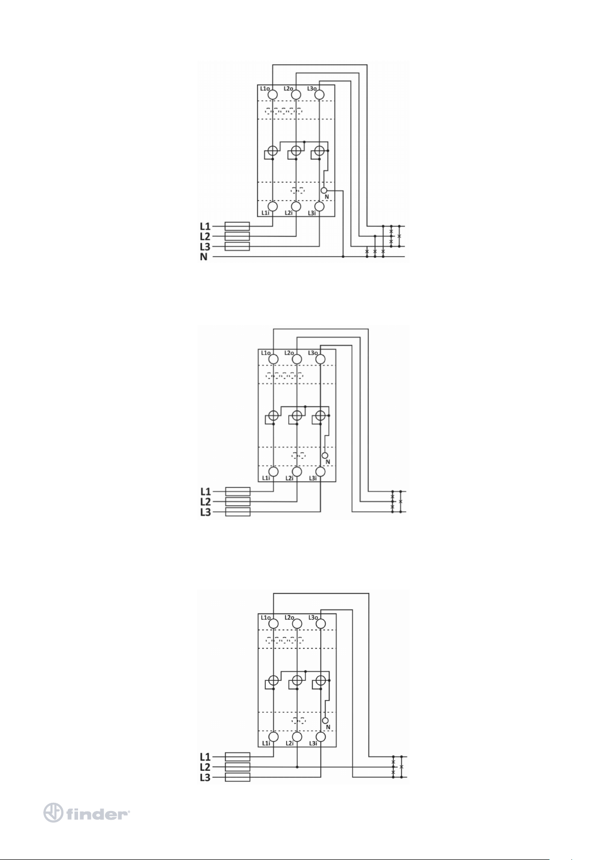
User’s Manual 7M 11
Figure 3: Three-phase 4-wire connection diagram (3L+N)
Figure 4: Three-phase 3-wire 3 system connection diagram (3L)
Figure 5: Three-phase 3-wire 2 system connection diagram (3L-2I)

User’s Manual 7M 12
Figure 6: Single.-phase connection diagram L+N
Figure 7: Connection diagram of S0 output, impulse counter, impulse counter or controller and tari clock
Figure 8: Connection diagram of S0 output, impulse counter, RS485 - Modbus and tari clock
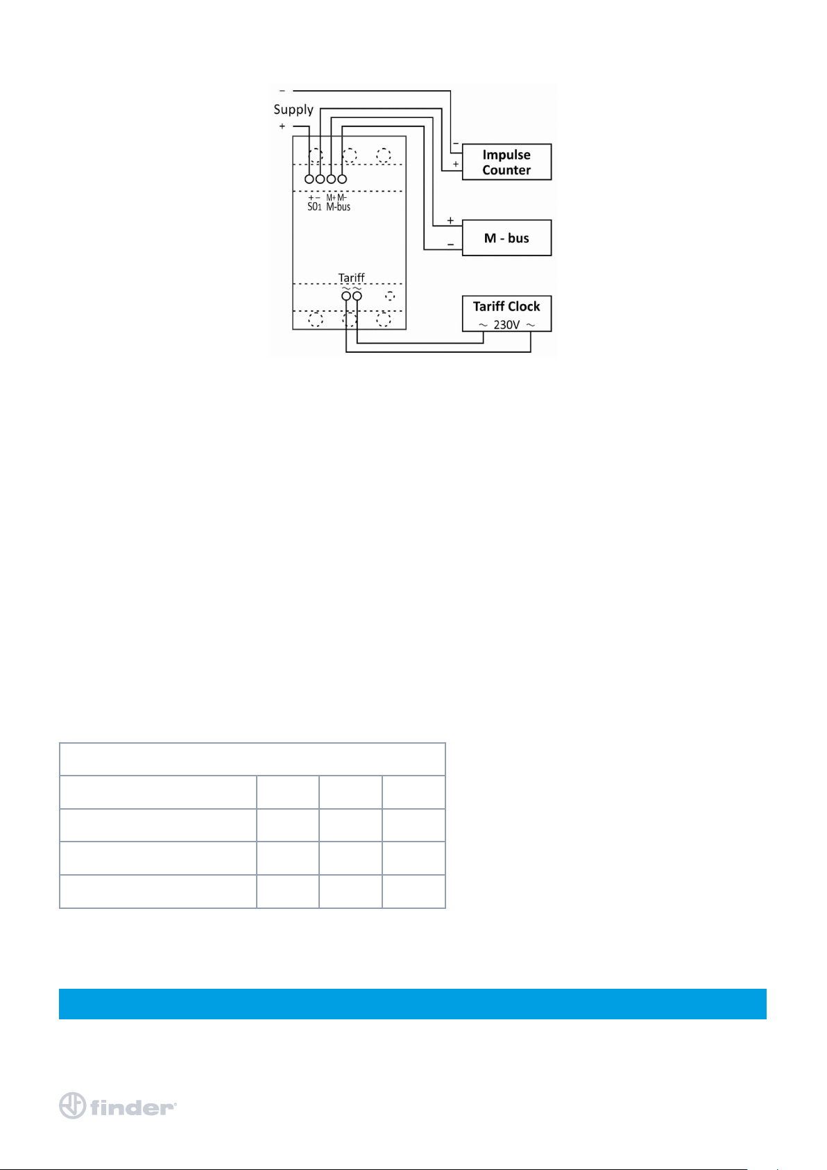
User’s Manual 7M 13
Figure 9: Connection diagram of S0 output, impulse counter, M - bus and tari clock
AUXILIARY CIRCUIT CONNECTION
For communication with outside world multiple manners are used:
• IR communication module (option) using MODBUS protocol.
It can be used for setting and testing the meter using USB adapter.
• S01,2 output module is used for counting number of pulses depending on consumed energy.
The S02 output can be programmed as alarm output.
• RS485 (option) communication module is galvanic isolated from meter main circuit.
It enables setting the meter, data readout in the network and tari setting.
• M-BUS (option) communication module is galvanic isolated from meter main circuit.
It enables setting the meter, data readout in the network and tari setting.
• NFC (option) enables an easy setting and downloading meter data via mobile app.
• Tari input (option) module is used to set active tari.
• LED diode is used for indication of no-load condition and test output proportional to measured active energy.
It can be also switched to reactive energy for test purpose using IR communication or cap touch.
• A capacitive touch button enables access to switch between measurements and settings in the menu.
Table 3: Survey of auxiliary circuit connection
PLEASE NOTE
Check markings on the side of the meter to check what modules are built in.
AUXILIARY TERMINAL
Pulse output (S01, S02) + –
Tari input ~ ~
M-bus (COM) M+ M-
RS485 (COM) A *SC B
*It is intended to be used for shielding for RS485

User’s Manual 7M 14
FIRST STEPS
Programming a three-phase electrical energy meter 7M.38.8.400.xxxx is very transparent and user friendly.
Numerous settings are organized in groups according to their functionality.
In this chapter you will nd basic programming steps:
- KEYBOARD NAVIGATION
- LCD USER INTERFACE
CALIBRATION AND SETTING PARAMETERS
FREEZE COUNTERS
KEYBOARD NAVIGATION
The capacitive touch (symbol below) is used for shifting between screens, for selecting the specic segment of the menu
and for conrming the settings. Press the capacitive touch (short-touch) to move forward between the screens. Long-touch
(approximately 3 seconds) is used to conrm the selection, to sett the next digit, or to enter the sub-menu. Very-long-touch
(approximately 5 seconds) considers the function ESC (during the parameter setting the screen goes back to the explicit
parameter in the other cases the LCD returns in the initial cycling mode).
If the screen backlight is o, the rst touch turns on the backlight, then the long-touch to view the main menu.
If the lock of the capacitive touch is available, to activate it, a very long-touch is needed.
Figure 10: The symbol of capacitive touch
LCD USER INTERFACE
LCD DISPLAY AT START UP
SN: serial number
MID: Version and CRC of Part 2
FUN: Version and CRC of Part 2
HW: Hardware version; m.: CRC of phase measuring modules (high, low)
Run: Operational time (days hours minutes)
After the electrical connection, the display shows an info screen (picture on top) for two seconds.
The following is holding page (default setting) of last observed measurement on the screen.
Measurements consist of energy counters and other actual measured values.
The MID approved meter shows a warning screen (picture on the right) Installation
Not set every 5 seconds if the installation of connection mode is not set yet.
Besides the holding page of measurement, one can enter the display menu structure by using a long touch. If the capacitive
touch is not pressed for more than 90 seconds, that specic measurement screen will be shown again.
This is also in case of a powerdown.
Cycling page function is a function that cycles measurements on the screen regarding the period that is dened in settings
(for more details see chapter Settings, Device settings, General settings, Display). If the capacitive touch is not pressed for
more than 90 seconds, the cycling of measurements automatically begines again. The explicit settings can be changed
through the Setting menu (for more details see chapter Display of device setting), Fi-MIS software or mobile app using NFC.
PLEASE NOTE
All settings that are performed can be subsequently changed via Fi-MIS by means of communication
PLEASE NOTE
The meter can be set to Test measuring mode which displays energy registers with better resolution.
The test mode is used for test purposes during type testing and test of meter constant during initial verication.
After power o meter automatically goes back to normal operation.

User’s Manual 7M 15
CAPACITIVE TOUCH SELF CALIBRATION PROCESS
In a reported xed 64s interval the average, minimum and maximum value of the capacitive touch sensor is calculated.
If the conditions are stable (without interruptions) then the average value of the capacitive touch sensor is used as a reference
value.
If the new reference value deviates suciently from the permanently stored value, it is permanently saved.
Permanently stored value is used when the power is turned on.
ENERGY COUNTERS
There are two sets of energy registers – four non-resettable registers which can be assigned for active energy (MID approved),
reactive energy (national approval) or apparent energy (no approval).
The meter with MID approval should have at least one register with active energy measurement.
There are additional 16 energy registers which can be parameterised by the user regarding type of energy, active quadrants,
direction of counting and tari and they can also be resetted using MODBUS command or cap touch.
On the LCD up to two energy counters are displayed.
There is the lock sign for the xed legally relevant non-resettable counters, the counter designation, the sign of currently
active register, an additional code and the unit.
For the code the user can choose between the OBIS code or letter description code (the latter is the default). The 9-digit
numerical number shows the value of the energy. The decimal dot is xed and resolution is xed to 100 Wh. The screen is
displayed for the pre-set cyclic period.
PLEASE NOTE
In compliance with the MID directive, where the nal test is done before selling the products, it may happen that the MID
energy meters show a low energy consumption even if they are new.
This can only happen to relatively small percentage of meters for each production lot and the highest value should be
around 6 kWh for the Active Imported Energy

User’s Manual 7M 16
Legally relevant non-resettable registers are designated with letters 1 to 4 after the lock sign, while legally non-relevant
resettable registers are designated with 01 to 16. The code is specied in table 4 and table 5.
REGISTER DESCRIPTION E1 TO E4 OBIS CODE LETTER DESCRIPTION CODE
Active energy Q1+Q4 – all taris 1.8.0 A.I.0
Active energy Q2+Q3 – all taris 2.8.0 A.E.0
Active absolute energy– all taris
(Abs(Q1+Q4) + abs(Q2+Q3)) 15.8.0 A.A.0
Reactive energy – Q1+Q2 - all taris 3.8.0 r.I.0
Reactive energy – Q3+Q4 - all taris 4.8.0 r.E.0
Reactive absolute energy– all taris 95.8.0 (manufacturer specication) r.A.0
Apparent absolute energy-all taris 9.8.0 S.A.0
Table 4: OBIS code and letter description code for E1 to E4
REGISTER DESCRIPTION C1 TO C16 OBIS CODE LETTER DESCRIPTION CODE
Active energy Q1+Q4 – all taris 1.8.0 A.I.0
Active energy Q1+Q4 – tari 1 to 6 1.8.1 to 1.8.6 A.I.1 to A.I.6
All energy types – tari 1 to 6 x.x.1 to x.x.6 x.x.1.to x.x.6
All energy types – mixed taris
(example tari 1 and tari 2) x.x.9 x.x
Active energy Q2+Q3 – all taris 2.8.0 A.E.0
free 15.8.0 A.A.0
Active energy (signed)– all taris
(Abs(Q1+Q4) – abs(Q2+Q3)) 16.8.0 A.b.0
Active energy Q1– all taris 17.8.0 A. .0
Active energy Q2– all taris 18.8.0 A. .0
Active energy Q3– all taris 19.8.0 A. .0
Active energy Q4– all taris 20.8.0 A. .0
Reactive energy – Q1+Q2 - all taris 3.8.0 r.I.0
Reactive energy – Q3+Q4 - all taris 4.8.0 r.E.0
Reactive energy – Q1 - all taris 5.8.0 r. .0
Reactive energy – Q2 - all taris 6.8.0 r. .0
Reactive energy – Q3 - all taris 7.8.0 r. .0
Reactive energy – Q4 - all taris 8.8.0 r. .0
Reactive absolute energy– all taris 95.8.0 (manufacturer specication) r.A.0
Apparent absolute energy-all taris 9.8.0 S.A.0
Apparent energy –Q1+Q4 – all taris 9.8.0 S.I.0
Apparent energy – Q2+Q3 – all taris 10.8.0 S.E.0
Other unspecied custom setting
regarding power, quadrants
0.0.y
y (0,1,2,3,4,9)
x. .y
x
x (A,r,S), y (0,1,2,3,4,» «)
Table 5: OBIS code and letter description code for C1 to C16

User’s Manual 7M 17
INITIAL DISPLAY MENU STRUCTURE
The following is a main menu divided into several sub-menus (ESC, Measurements, Info, Settings, Resets, Installation).
MAIN MENU:
- ESC
MEASUREMENTS
INFO
SETTINGS
RESETS
INSTALLATION
www.ndernet.com / Temperature 27 °C
ESC
Long-touch ESC, the screen holds on to the chosen measurement on default mode.
The mode could be changed in Fi-MIS software, to counter n1 or to cycling mode
(cycling between measurements). Short-touch to shift between sub-menus.
DISPLAY OF DEVICE MEASUREMENTS
Short-touch Measurements, the sub-menu is entered (ESC, Present values, Limits).
Long-touch ESC to return to the main menu.
Long-touch Present values to observe the specics measurements or Limits to observe
the limits.
MEASUREMENTS
ESC
Present values
Limits
<= Main menu
PRESENT VALUES
PRESENT VALUES
ESC
Voltage
Current
Power
PF & Power angle
Frequency
Energy
THD
Custom
Overwiew
<= Measurements
Long- touch Present values, the sub-menu is entered (ESC, Voltage, Current, Power, PF & Power angle, Frequency, Energy,
THD, Custom, Overview). Long-touch ESC to return to the measurements menu. Short-touch to shift between sub-menus.

User’s Manual 7M 18
VOLTAGE
Long-touch Voltage to observe the phase voltage, phase to phase voltage, voltage angle,
average values of phase voltage, and average values of phase to phase voltage.
CURRENT
Long- touch Current to observe the phase current, and average current.
POWER
Long- touch Power to observe the power (active, reactive, apparent),
phase power (active, reactive, apparent).
PF & POWER ANGLE
Long- touch PF & Power angle to observe the power factor and power angle,
phase power factor and phase power angle.

User’s Manual 7M 19
FREQUENCY
ENERGY
Long- touch Energy to observe the measured energy.
Two dierent types of energy registers are shown (resettable and non-resettable).
Disabled energy counters are not shown on the screen.
The resettable energy counter (Non-MID meters) can be reset, while the non-resettable
(the symbol of lock representing it) has been measuring the quantity continuously.
The resettable energy counters enable to set the value of measured energy
(see chapter Settings, energy, counters).
The energy counter you reset starts to re-measure the value from the zero
THD
Long- touch THD to observe the total harmonic distortion of current and voltage.
This manual suits for next models
2
Other finder Measuring Instrument manuals


