Marine Magnetics SeaSPY2 User manual

SeaSPY2
Operation Manual
Rev. 2023-12
Marine Magnetics Corporation
135 SPY Court
Markham, Ontario
L3R 5H6
Canada
Tel: 1-905 479-9727
fax: 1-905 479-9484
support@marinemagnetics.com
www.marinemagnetics.com

SeaSPY2 Operation Manual v.6.5
Revision 6.3 ii
Contents
1...INTRODUCTION................................................................................1
1.1 Understanding the System Components 1
1.1.1 Overhauser Total Field Sensor 1
1.1.2 Leak Detector 2
1.1.3 Pressure Sensor 2
1.1.4 Altimeter echo sounder (Optional) 2
1.1.5 Electronics Module 3
1.1.6 Towfish 3
1.1.7 Isolation Transceiver 3
1.1.8 Gradiometer Transceiver (discontinued) 3
1.1.9 USB Cable 3
1.1.10 RS232 Cable (Optional) 3
1.1.11 AC Power Supply 4
1.1.12 Battery Clip Cable (Optional) 4
1.1.13 Tow Cable 4
1.1.14 Floatation Cable (Optional) 4
1.1.15 Deck Cable 5
1.1.16 BOB Software 5
2...COMMUNICATION VIA THE ISOLATION TRANSCEIVER............... 6
2.1 Transceiver Serial interface 6
2.2 Transceiver Internal Real-Time Clock 6
2.3 Transceiver Output Voltage 6
2.4 Transceiver Status LEDs 7
2.5 Text and Binary Modes 7
3...CONNECTING THE EQUIPMENT ..................................................... 8
3.1 Main Tow Connector 8
3.2 Longitudinal Gradiometer 10
3.3 Horizontal Transverse Gradiometer 10
3.3.1 Horizontal Gradiometer Assembly Instructions 11
3.3.2 Spare fasteners for the frame clamping bolts: 14
4...GETTING STARTED........................................................................ 15
4.1 Setting pressure sensor zero-depth level 15
4.2 Getting Started with a New Gradiometer System 15
4.3 Upgrading to a Gradiometer System 15
5...SEASPY2 COMMANDS .................................................................. 16
5.1 Normal Commands 16
5.2 Gradiometer Mode Commands 18
5.3 Isolation Transceiver Commands 19
6...SEASPY2 DATA FORMAT.............................................................. 20
6.1 Standard Format 20
6.1.1 Warning Messages 21
6.2 Compact Format 21
6.3 SIS-1000 Compatible Format 22
6.4 Gradiometer Data Format 22
7...INTERFACING TO A SIDE SCAN SONAR ..................................... 23
7.1 Analog Systems 23

SeaSPY2 Operation Manual v.6.5
Revision 6.3 iii
7.2 Digital Systems 23
7.3 Communication 23
7.4 Baud Rate 23
7.5 Electrical Power 24
7.6 Mechanical Tow Point and Electrical connector Pin-out 24
8...ESTIMATING TOWING DEPTH....................................................... 25
9...INSIDE THE TOWFISH.................................................................... 27
9.1 Standard Towfish 27
10 .MAINTENANCE............................................................................... 29
10.1 Deployment and Storage Tips 29
10.2 O-ring sizes 30
11 .TROUBLESHOOTING ..................................................................... 31
11.1 Transceiver Test Procedure 31
11.2 SeaSPY2 Test Procedure 32
11.3 Side Scan Integration Test Procedure 33
11.4 Gradiometer Test Procedure 34
11.5 Troubleshooting Specific Issues 35
11.6 Electrical Specifications 37
12 .HOW TO REACH US ....................................................................... 38
13 .WARRANTY .................................................................................... 39
13.1 Indemnity 39
13.2 Disclaimer 39

SeaSPY2 Operation Manual v.6.5
1
1Introduction
SeaSPY2 is a high-sensitivity total field magnetometer packaged in a rugged marine housing that is designed to be towed
behind a marine vessel. A standard SeaSPY2 system consists of the following components:
•A towfish unit that contains an Overhauser magnetometer sensor and driving electronics
•A high-strength marine tow cable, containing a single twisted wire pair
•A deck leader cable that is waterproof, but designed to be used out of water
•An isolation transceiver for powering and communicating with the towfish, and time synchronization
•An RS232 interface cable that connects to a standard PC RS232 port
•A universal input (100 to 240VAC 50/60Hz) power supply that allows the system to be powered from line power
anywhere in the world
•BOB software for Windows 10 or later.
See BOB User Manual for minimum recommended requirements for optimal BOB operation.
Measurement of the magnetic field is done completely inside the towed fish. The tow cable supplies power to the towfish, and
provides a bidirectional digital communication link. All control of the fish is through RS232, using a PC or any RS232–capable
computer.
The towfish requires DC power, with a range of +15 to +50VDC. For medium or long tow cables (longer than 300m), it is
recommended to keep the supply voltage above +20VDC, and it is always recommended to keep the supply voltage as high as
possible to reduce the voltage drop in the tow cable. In most cases, power will be supplied to the SeaSPY2 from the Isolation
Transceiver, which produces a clean, constant +48VDC to power the towfish. The input range for the Isolation Transceiver is +9
to +28VDC.
The AC power supply (included with all complete SeaSPY2 tow systems) will produce a clean, constant +24VDC from a 100 to
240VAC at 50/60Hz source. The maximum power consumed by the fish is about 3W when acquiring data, and is typically
around 1W when in standby. The Isolation Transceiver consumes an additional 1.5W.
1.1 Understanding the System Components
Marine Magnetics supplies a separate document called our SeaSPY2 Technical Application Guide that describes in depth how a
SeaSPY2 magnetometer works, and how it can be used for different applications. Marine Magnetics provides this document to
anyone free of charge, so please contact us if you do not already have a copy.
1.1.1 Overhauser Total Field Sensor
This is the main sensor of the system. It operates on the proton spin resonance principle, but it is drastically different from a
conventional proton magnetometer sensor. The proton-rich liquid within the sensor has been specifically engineered to allow a
principle known as the Overhauser effect to occur within it. This effect allows a SeaSPY2 magnetometer to measure with one to
two orders of magnitude more sensitivity but with a tiny fraction of the power of a standard proton sensor, while keeping the
excellent absolute accuracy and operational characteristics that have made conventional proton sensors so popular.
All SeaSPY2s are supplied with an omnidirectional sensor that is completely isotropic with respect to magnetic field direction.
The only restriction that must be observed is that the fish must not be oriented vertically with the nose facing up. This is a
restriction with respect to the direction of gravity, not magnetic field.
The Overhauser sensor measures magnetic flux density, the unit for which is the Tesla (T). Magnetic flux density on the surface
of the Earth typically varies between about 18µT to 70µT, depending on location. The flux density at any fixed location on the
Earth’s surface also varies with time due to diurnal effects, which include influence from the Sun, and movement of the Earth’s
molten interior.
One often speaks of a magnetometer as measuring magnetic field instead of flux density, since the two values are directly
related given an environment of constant magnetic permeability (such as air or water). Some materials will distort the
surrounding magnetic flux density by ‘amplifying’ or adding to the ambient magnetic field. Such objects are known as
paramagnetic. Some materials (such as iron, nickel, cobalt and alloys containing these materials) exhibit this effect very
strongly, and are known as ferromagnetic. Objects made from these materials are very easily detectable by a magnetometer.
Most building materials, especially those used to build modern boats and ships, contain iron alloys and are therefore magnetic.
Some stainless steels (austenitic alloys such as 316) are only weakly ferromagnetic, but will become more strongly magnetic if
their microstructure is disturbed by annealing, welding, machining or severe stressing.
When an object of high magnetic permeability distorts the flux density around it, it creates a magnetic gradient that is
proportional to the magnitude of its permeability. If the magnetic gradient through the volume of the magnetometer sensor is

SeaSPY2 Operation Manual v.6.5
2
too great, the sensor will not operate correctly. For this reason, massive magnetic objects must be kept away from the sensor.
Do not expect the sensor to produce good results on the deck of a ship, or inside a building, any more than you would expect
a high-powered telescope to see distant stars in the middle of the day.
For more information on magnetic fields and how SeaSPY2 magnetometers work, please refer to the SeaSPY2 Technical
Application Guide. This document can be obtained from Marine Magnetics.
1.1.2 Leak Detector
Each SeaSPY2 magnetometer is equipped with a leak sensor that sounds a warning when water is present inside the towfish
housing. Every reading, in text mode, displays an ’Lx’ parameter, where x is a number between 0 and 9. A value of 9 indicates
that water is present. Even a small drop of water will activate the leak sensor.
In the event of a leak warning, the SeaSPY2 should be retrieved immediately, as it is very likely that a leak has developed in
the electronics housing. Water inside the electronics pod may damage the electronics module and Overhauser sensors.
1.1.3 Pressure Sensor
The standard SeaSPY2 pressure sensor is a Wheatstone bridge on a silicon diaphragm. The maximum pressure that this sensor
can stand before potentially suffering damage is 2500psi (1725m of water). Exceeding this depth can cause a change in the
calibration tuning of the sensor, and its accuracy may suffer as a result. The pressure sensor will not suffer serious mechanical
damage (i.e. will not rupture and cause a leak) until twice that pressure (about 3450m of water).
Note that the standard SeaSPY2 housing as a whole is rated to a depth of 1000m, which should never be exceeded or
damage to the housing may result.
SeaSPY2s can interface seamlessly to a variety of other pressure sensors, suited for shallow or deep water surveying. In general,
a larger pressure sensor range will result in lower precision in the pressure reading. The table below lists the different pressure
sensor types, their required housing ratings, and the corresponding maximum precision.
Pressure Range (psi) Depth Range (m) Precision Housing
500 345 0.1 m 1000m standard
1500 1000 0.3 m 1000m standard
5000 3450 1 m 3000m deep-tow
10000 6895 2 m 6000m deep-tow
table 1-1: Pressure sensor options
The pressure sensor is an analog device that may drift with temperature and with time. For proper operation, the pressure
sensor zero-level should be reset before every survey. In moderate climates, this can be done on the deck of your ship;
however, for optimal results the towfish should be submerged to allow the temperature of the pressure sensor to reach the
ambient water temperature. The pcommand will zero the pressure sensor.
The Pcommand will display the current pressure sensor calibration settings, and will offer the option to set the full-scale
pressure calibration. The full-scale calibration is factory-set, and does not need to be altered by the operator unless below-
nominal full-scale accuracy is suspected.
The pressure sensor may be calibrated by entering the factory full-scale calibration value; by entering a nominal value that is
valid for a generic sensor of a given pressure range; or by submerging the towfish to a known depth and entering that depth.
1.1.4 Altimeter echo sounder (Optional)
A 200 kHz narrow-beam echo sounder is located on the bottom of the nose bulkhead altimeter block. This device senses the
distance from the face of the transducer to the sea floor by emitting 10 sound pulses per second, and providing these altitude
readings to the SeaSPY2 electronics.
The SeaSPY2 altimeter has a range of 0.5m to 60m, and a resolution of 0.01m. To see the current altitude of the platform, use
the d command. Altitude is displayed in meters as ‘A005.00m’. In addition, an altitude reading is included in every magnetic
field reading to allow real-time monitoring. Note that the altitude data field does not appear if the altimeter is not installed in
the towfish.
The altimeter does not work when out of the water, and will display a value of 599.99m representing an out-of-range condition.
This indicates that the altimeter cannot ‘find’ a surface underneath the platform, but otherwise working properly. If the
altimeter were to stop working, the altitude reading would disappear from the data stream completely.

SeaSPY2 Operation Manual v.6.5
3
1.1.5 Electronics Module
The SeaSPY2 electronics module is the core of the SeaSPY2 system, located within the towfish. It controls all of the sensors in
the towfish, monitors their performance, and reports their data to the host acquisition device digitally over the tow connection.
Interface to the electronics module is through a single two-wire connection. DC Power and telemetry are multiplexed into the
same two connections.
The electronics module requires approximately 700mW of power in standby (waiting for commands), and approximately 2.7W
at full power while sampling the magnetic field.
All SeaSPY2 electronics modules are completely interchangeable. The only difference between them is a 16-bit serial number
that is stored in non-volatile RAM within the unit.
1.1.6 Towfish
The SeaSPY2 towfish is a pressurized vessel that carries all of the system sensors and the SeaSPY2 electronics module. It
consists of 2 filament-wound fiberglass cylinders coated with polyurethane for abrasion and shock resistance. The nose
contains a brass tow connector that is designed to bear the entire load of the tow system, in addition to providing an electrical
connection. Note that the shell of the connector is isolated from the system common ground, and is connected electrically to
the surrounding water.
A standard SeaSPY2 towfish is rated to a water depth of 1000m (3280ft). For maintenance recommendations and a list of
replacement O-ring sizes in the housing seals, refer to section 10 (page 29).
1.1.7 Isolation Transceiver
The SeaSPY2 Isolation Transceiver contains three important components:
•power-conditioning electronics that supplies clean constant electrical power to the SeaSPY2
•microprocessor to bridge the communication between the magnetometer FSK protocol and the PC’s RS232 interface
•Integrated GNSS receiver that ensures precise time synchronization of the connected magnetometer (beginning in 2023)
Power and RS232 are both fully isolated from the supply ground, providing extremely high immunity to noisy power supplies at
all frequencies. The wide input range of +9VDC to +28VDC allows for operation with both 12VDC and 24VDC lead acid batteries.
Internal regulators produce a constant +48VDC to power the SeaSPY2. The power and communication to the SeaSPY2 are
multiplexed together for use with a two-conductor tow cable. The isolation transceiver is sealed in a rugged housing that is
splash proof, but not waterproof.
The Isolation Transceiver is able to communicate with a SeaSPY2 platform across up to 10,000m (32,808ft) of the standard
SeaSPY2 twisted-pair tow cable.
The transceiver also supports USB interface for use with computers that do not have a standard serial port. For more
information on how to connect the transceiver, refer to Sections 2 and 3.
A new generation Isolation Transceiver is available as of 2023, which includes an additional connector for the external GPS
input. An external GPS adapter cable allows the transceiver to receive time synchronization data from an external RS232 GPS,
whenever the integrated GPS is unable to receive satellite signal (e.g. when the transceiver is placed inside a vessel’s cabin).
1.1.8 Gradiometer Transceiver (discontinued)
The Gradiometer Transceiver has been discontinued in 2023, and replaced with the GPS-enabled 4-port universal transceiver.
1.1.9 USB Cable
The USB cable connects the Isolation Transceiver to your PC. It is a gray cable with one USB connector that plugs into the PC,
and one female 8-pin circular connector that connects to the Isolation Transceiver.
This cable is useful for laptops or computers that do not have a standard serial port. The Isolation Transceiver contains a built-in
RS232-USB adapter, which acts as a virtual COM port on the computer. The USB driver for this adapter is supplied with BOB
software. Please note that this virtual COM port is available only when the transceiver is powered.
1.1.10 RS232 Cable (Optional)
The RS232 cable is an optional replacement for the USB cable. It is a gray cable with one female 9-pin DSUB connector that
plugs into the serial port of your PC, and one female 8-pin circular connector that connects to the Isolation Transceiver. An
RS232-USB adapter (commercially available) can be used for computers lacking a serial port. Unlike the USB cable, using an
external RS232-USB adapter makes the virtual COM port available even when the transceiver is not powered.

SeaSPY2 Operation Manual v.6.5
4
1.1.11 AC Power Supply
The standard SeaSPY2 AC power supply can accept any AC power from 100 to 240VAC, at 50/60Hz, and is therefore capable of
operating worldwide. It produces a constant 24VDC to power the Isolation Transceiver and SeaSPY2 system.
Note that the AC power supply uses a 3-prong North American style plug. It is extremely important that the third (middle)
prong from this plug is connected to a proper ground. If not, you may experience communication problems, or even a
degradation of magnetometer performance.
The Isolation Transceiver contains protection against polarity reversal. Therefore, connecting the black clip to the positive
terminal, and the red clip to the negative terminal will cause no damage. However, no protection exists against over-voltage.
Use caution not to connect the battery clips to any voltage higher than 28V.
1.1.12 Battery Clip Cable (Optional)
If AC power is unavailable, or if battery power is more convenient, the battery clip cable may be connected in place of the AC
power supply. This cable has two large alligator clips for easy connection to a standard 12VDC or 24VDC vehicle battery.
Note that the voltage of a typical 12VDC lead-acid battery will vary from approximately 14VDC when fully charged to
approximately 9VDC when nearly discharged. A 24VDC lead-acid battery will provide a range of 18 to 28VDC going to the
SeaSPY2 system over the full charge cycle of the battery set.
Connecting two 12V batteries in series can also provide a 24V power supply.
When using a gradiometer with altimeters, a 24V power supply is required to meet the added power demand.
The SeaSPY2 system has protection against polarity reversal. Therefore, connecting the black clip to the positive terminal, and
the red clip to the negative terminal will cause no damage. However, no protection exists against over-voltage. Use caution not
to connect more than 28V to the SeaSPY2 system.
1.1.13 Tow Cable
The standard SeaSPY2 tow cable (yellow in colour) is a shielded twisted pair (two conductors plus shield) with a high strength,
lightweight braided Vectran strength member. The tow cable can withstand loads of up to 1000lb without any damage, and
loads of up to 6000lb without breaking. It is sheathed in a tough polyurethane jacket and is fully water blocked. This means that
if the jacket is cut or damaged, water migration through the tow cable will be greatly slowed, but not completely stopped
depending on the external pressure. A damaged cable jacket should be repaired as soon as possible.
The two conductors in the tow cable carry the towfish DC power, and also the towfish telemetry, multiplexed with the power
supply. The red conductor carries the positive voltage and telemetry, and the black conductor carries the negative voltage and
common ground. The outer braid is only used to shield the inner two wires from external noise, not to carry electric current. It
is connected to the cable’s negative conductor at the source (topside) end of the cable only.
Tow cable length must be adjusted appropriately before entering it into the survey data collection software (such as BOB or
Hypack). The magnetometer sensor is located at the back of the SeaSPY2 towfish, increasing the effective length of the tow
cable. Use of a Y-split cable (for horizontal gradiometers) further increases the effective cable length. Refer to table 1-1.1 to
determine the tow cable length adjustment:
Magnetometer model Tow cable length adjustment
Explorer + 0.6 m
SeaSPY2 + 1.0 m
SeaSPY2 + Altimeter + 1.1 m
SeaSPY2 Horizontal gradiometer + 3.5 m
table 1-1.1: Adjustment required to determine the effective tow cable length for different magnetometer models
1.1.14 Floatation Cable (Optional)
The SeaSPY2 floatation cable is mechanically and electrically similar to the standard SeaSPY2 tow cable, but has the addition of
a syntactic foam layer underneath its outer polyurethane jacket. It is distinguishable by its larger thickness and orange colour.
The floatation cable provides enough buoyancy to keep the magnetometer at a depth of about 2 to 3m, regardless of how
much cable is deployed.
Floatation cable is very useful for shallow water environments, or when deploying with a great deal of other gear (such as
seismic guns and streamers) when it is important keep the cable at a controlled depth, visible to the operators at all times.
SeaSPY2 Operation Manual v.6.5
5
1.1.15 Deck Cable
The deck cable is designed to connect the main tow cable spool, which is usually left on the deck of the deployment vessel near
the stern, to the Isolation Transceiver, which is normally kept in a controlled interior environment. The deck cable’s jacket is
very tough polyurethane that is designed to withstand extreme abrasion and crushing, but is not designed to withstand towing
force.
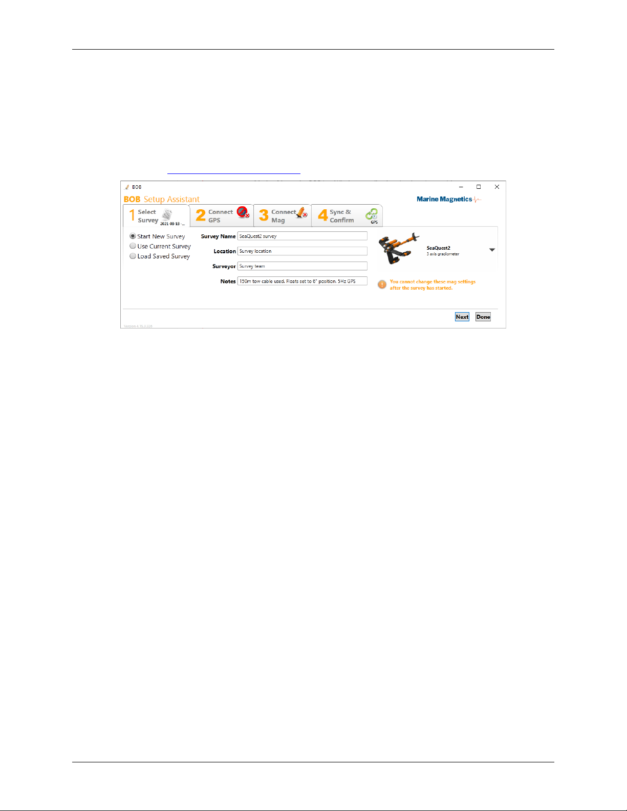
1.1.16 BOB Software
Marine Magnetics BOB is a Windows application that interfaces with your magnetometer, to allow full control over the towfish,
data collection, survey planning and data visualization. For detailed information on using this program refer to the BOB
Operation Manual. Visit: https://bob.marinemagnetics.com/

SeaSPY2 Operation Manual v.6.5
6
2Communication via the Isolation Transceiver
By default, all communication with the SeaSPY2 is via the Isolation Transceiver, which inserts an intelligent layer between data
logging software and the towfish. The transceiver assumes complete control over the tow cable communication link, and time
synchronization with the GPS, as well as supplies optimal power to the towfish for a wide variety of cable lengths and
specifications.
2.1 Transceiver Serial interface
The connection between the data logging computer and the Transceiver is via RS232 interface, using:
•115200 baud
•8 data bits
•No parity
•1 stop bit
Communication is full-duplex. Any commands that are sent to the SeaSPY2 while it is transmitting will not disrupt the
transmission.
When using the supplied USB cable, the transceiver’s integrated RS232-USB converter is used, which emulates a virtual COM
port with the same settings.
When you send a command to transceiver, you may get a response even if there is no SeaSPY2 connected. For example, you
can query and set the transceiver’s internal time and date without the SeaSPY2 connected. As soon as you connect the
SeaSPY2, the transceiver will recognize the SeaSPY2, and set its time as necessary.
Refer to Section 6 (page Error! Bookmark not defined.) for details on the command interface.
2.2 Transceiver Internal Real-Time Clock
The Isolation Transceiver contains a real-time clock that it used to synchronize the clock inside the SeaSPY2 during the survey.
The transceiver real-time clock continues running when power is disconnected. The clock is powered by an internal lithium
battery that automatically recharges when power is applied to the transceiver. The clock will keep time accurate to 0.65
seconds per day in ambient temperatures of –40 to +85˚C, or accurate to 0.15 seconds per day in ambient temperatures of 0 to
+40˚C.
Note that after an extended storage period between surveys (several weeks), the internal real-time clock battery may discharge
and the clock will reset to zero. For this reason, it is recommended to “charge” the transceiver for at least 6 hours prior to the
survey following an extended period of storage. This will ensure that the real-time clock battery will be sufficiently charged to
ignore any power cycles that may occur during the survey.
2.3 Transceiver Output Voltage
Standard isolation transceiver units are built to output +48VDC to the SeaSPY2 tow cable, using input voltages of +9 to +28VDC.
Power and RS232 are both fully isolated from the supply ground, providing extremely high immunity to noisy power supplies at
all frequencies.
Note that all isolation transceiver units use a 1.0A resettable input fuse. If your input voltage is too low, the transceiver will
have to draw more current to supply the same power to the SeaSPY2 tow system. For this reason a 24V input source is
recommended for most situations.
The resettable fuse has a variable trip delay based on the amount of over-current. For example, if the transceiver is drawing
1200mA, you may find that the SeaSPY2 system will work well for a short while, and then trip the fuse for no apparent reason.
If your transceiver seems to ‘go dead,’ it is possible that you have simply tripped the fuse due to input voltage being too low.
Simply power down the system, wait a few seconds, and then turn it on again.
You can monitor the transceiver input and output voltages and currents at any time using the dcommand. Refer to Section 6
(page Error! Bookmark not defined.) for details on the command interface.

SeaSPY2 Operation Manual v.6.5
7
2.4 Transceiver Status LEDs
The Isolation Transceiver has three status LEDs, indicating power, communication with towfish, and GPS lock.
(the GPS LED was introduced in 2023).
The LED modes indicate the following states:
Power LED
Orange Towfish not connected/detected.
Green Towfish is detected and powered.
Red Fault condition. Or Transceiver
disabled power to towfish.
Communications LED Blue (flashing) Data is being transmitted.
GPS Lock LED*
Blue (flashing) Searching for GPS signal.
No satellite lock.
Blue (solid)
GPS satellite signal lock is obtained,
and the transceiver is able to
synchronize itself and the connected
towfish to the GPS time.
Table 2-1 - LED indicators on the Isolation Transceiver
2.5 Text and Binary Modes
Two modes of communication are possible with a SeaSPY2 magnetometer. Text mode is the simplest method of communicating
with a single magnetometer on a single tow cable. In this mode, only a simple ASCII terminal is required, which can be a PC
running a terminal program such as Windows HyperTerminal, or BOB software provided with your magnetometer system. In
text mode, the fish responds to single byte commands sent from the terminal.
Binary mode is a less intuitive, yet more efficient mode of communicating that is intended to be used by automated data
collection systems. Commands and data are sent and received in a special protocol that requires decoding software on the host
(user) end. This protocol allows more than one magnetometer to be connected to the same tow cable, creating an along-the-
track gradiometer configuration. A user can switch to binary mode from text mode by sending the @command. After this,
commands must be sent according to the special binary protocol.
If SeaSPY2 is inadvertently placed into binary communication mode, it will not respond as expected to standard text mode
commands, and may seem as if it is malfunctioning. If your fish does not seem to be responding to commands, send the #
command at least twice to return to text mode. Turning SeaSPY2 off and on again will reset its communication mode to text.

SeaSPY2 Operation Manual v.6.5
8
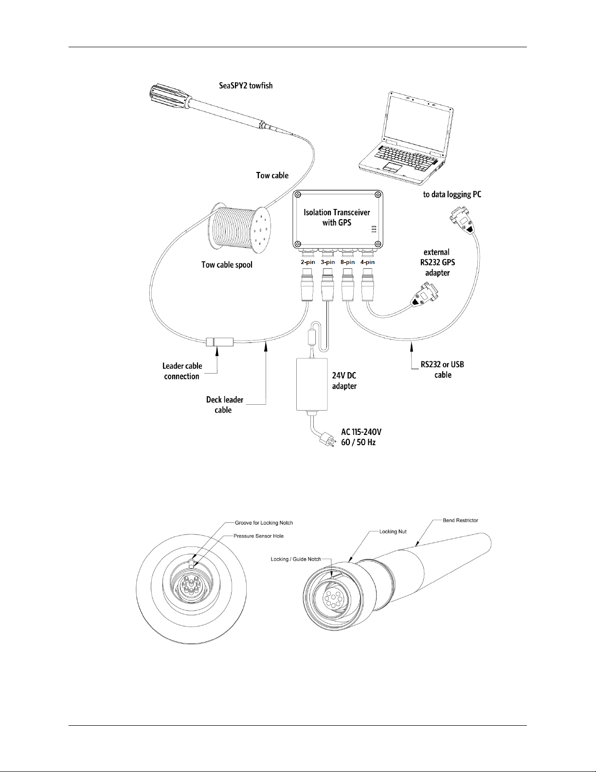
3Connecting the Equipment
The SeaSPY2 magnetometer system is designed for quick and easy deployment and can be setup without the use of any tools.
Refer to Figure 3-1on page 9 for a system connection diagram.
If you are using a side scan sonar with your magnetometer, refer to Section 7 (page Error! Bookmark not defined.) for further
instructions.
•Connect the Isolation Transceiver to a PC or other type of host computer using either the USB or the RS232 cable
provided with the system. If your PC does not have an available serial port, you can use either a USB-to-Serial
converter.
•If you are powering your unit from an AC power source, plug the circular 3-pin female connector end of the AC
adapter into the transceiver and then plug the power cable into 100-240VAC, 50/60 Hz. The unit can also be powered
from a DC source using the optional Battery Clip Cable by connecting the two large alligator clips to the battery
terminals and the circular 3-pin female connector to the transceiver. Refer to Section 1.4.8 (page Error! Bookmark
not defined.) for further details on the Isolation Transceiver.
•The deck leader is a long black cable (typically 20 to 30 feet) that connects the transceiver to the main tow cable. Plug
the circular 2-pin male connector end into the transceiver and then plug the coax connector on the other end into the
main tow cable of the system. Note that the deck leader is not designed for underwater use and is not designed to
withstand any towing force. Its connectors are sealed but not submersible.
•The tow cable must be firmly secured to the towing vessel. On larger vessels, this is sometimes done by winding the
tow cable on a secured winch, and connecting the deck leader to the slip ring connection on the winch. The deck
leader then provides a connection between the winch and the transceiver, which is typically in an enclosed area close
to the data acquisition equipment.
•When using a tow cable spool without a slip ring, always disconnect the deck leader cable from the tow cable spool
before adjusting the tow cable length.
3.1 Main Tow Connector
The main tow connector provides the electrical connections to the towfish, and also bears the load of the towfish as it is towed
through the water. It is a rugged, heavy-duty connector that is able to withstand a great deal of physical punishment.
The male connector has a locking slot that fits into a groove in the female side. When assembling the connector, line up the slot
with the groove, and insert. The male connector should slide in all the way up to the locking ridge. Use the brass locking nut to
fasten the connector in place. Do not be afraid of over-tightening this nut. It is too strong to be damaged by hands alone.
When the connector is assembled, no part of the thread on the towfish should still be visible. If it is, the nut has not been
tightened fully, or the slot was not inserted properly in the groove. Also, if you can still rotate the bend restrictor after the
connector has been assembled, the slot was not inserted properly in the groove.
The most important feature of the tow connector is that all parts are fixed in place when it is fastened – no part moves against
any other part. If you have used shackle connections on other marine instruments in the past, you will notice a great benefit to
the ruggedness and longevity of the SeaSPY2 connection system. Keeping the connector in operational order requires very little
effort. See section 10.1 for maintenance tips.
SeaSPY2 Operation Manual v.6.5
9
•
•Figure 3-1 - SeaSPY2 connection diagram with a GPS-enable Isolation Transceiver
NOTE: The external GPS connection is optional, for situations where internal GPS is not exposed to satellite signal.
Figure 3-2 - SeaSPY2 main tow connector
STANDARD MAIN TOW CONNECTOR
(CABLE TERMINATION)
STANDARD MAIN TOW CONNECTOR
(TOWFISH)
SeaSPY2 Operation Manual v.6.5
10
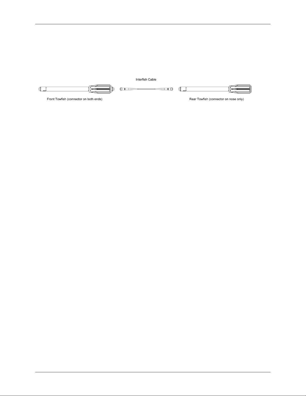
3.2 Longitudinal Gradiometer
A Longitudinal Gradiometer system consists of two SeaSPY2 units connected in line via an interfish cable. The two towfish can
be towed from a standard main tow cable but require the Isolation Transceiver to be switched to Gradiometer Mode in order to
communicate properly. Figure 3-4 shows how to assemble a Longitudinal Gradiometer system. The front towfish in the
assembly has a tow connector on both ends. If you are using gradiometer towfish alone, always make sure that the tail plug
with seal is in place, or else the towfish can be damaged.
Figure 3-3 - Longitudinal gradiometer assembly
3.3 Horizontal Transverse Gradiometer
The SeaSPY2 Horizontal Gradiometer expansion kit converts two standard SeaSPY2 magnetometer towfish into a simultaneous
horizontal gradiometer. The kit consists of a rigid frame structure, and a Y-split tow cable that carries the SeaSPY2 power and
telemetry signals simultaneously to both towfish from a single tow cable. A Gradiometer Transceiver is required for
communicating with the two towfish. The Gradiometer Transceiver software supports simultaneous communication of two
SeaSPY2 magnetometer towfish over the same single twisted-pair tow cable; it combines data streams from both towfish into
one data stream sent to the data logging computer, and handles time synchronization of both towfish.
The gradiometer frame features a streamlined design to minimize drag, and is constructed from hard-anodized aluminum,
making it relatively lightweight, yet very strong, rigid and resistant to damage from collisions with obstacles while being towed.
The frame’s high rigidity is very important for producing precise, high-quality gradiometer data.
The aluminum frame is anodized to prevent corrosion, and is additionally equipped with sacrificial anodes made of zinc for
harsh salt water environments. These anodes are designed to corrode first, thus preventing corrosion of the aluminum frame.
As the anodes corrode over time, they may require replacement.
Note that the fasteners used to attach the anodes must be completely non-magnetic in order to ensure proper operation of the
gradiometer. Only brass or titanium fasteners can be used.
IMPORTANT: Do not attempt to replace any frame fasteners with replacement ones, if you cannot obtain 100% non-
magnetic fasteners. Only titanium or Naval Brass are sufficiently non-magnetic so as to exclude any possibility of magnetic
interference. Using stainless steel fasteners anywhere on the frame will cause magnetic interference and compromise the
sensitivity and performance characteristics of the gradiometer.
SeaSPY2 Operation Manual v.6.5
11
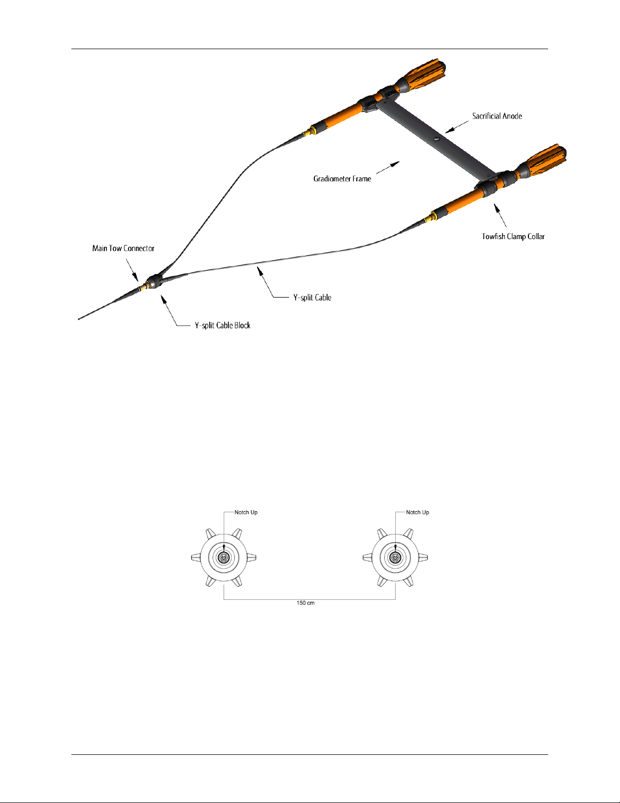
Figure 3-4 - The horizontal gradiometer in fully assembled state
3.3.1 Horizontal Gradiometer Assembly Instructions
The horizontal gradiometer frame is shipped as a fully assembled streamlined transverse “wing” with two clamp collars on each
side and non-magnetic brass or titanium fasteners. The clamping bolts located in the center of each collar contain rubber O-ring
washers to prevent loosening through vibration.
Step 1: Position the SeaSPY2s
For proper frame alignment, lay the two SeaSPY2’s on the ground 150 cm apart with the tow connector notch facing up as
shown in Figure 3-5. If the SeaSPY2’s are equipped with altimeters, the altimeters should be pointing downward when the
connector notch points upward. This alignment ensures that the internal ballast in each SeaSPY2 is facing downward.
Figure 3-5 - Correct towfish orientation prior to attaching the frame

SeaSPY2 Operation Manual v.6.5
12
Step 2: Loosen the clamping bolts in the collars just enough to allow the collar to slide over the SeaSPY
In order to install the assembled frame onto the SeaSPY2, simply loosen the clamping fasteners (one on each collar) enough to
allow the collar to slide onto the SeaSPY2. Take care not to lose the nut on the opposite side of the bolt as you loosen it! It is
not necessary to remove the collar from the wing. The rubber O-ring washers are required to prevent the collar fasteners from
getting loosened should any unnecessarily harsh vibration occur during the survey.
Step 3: Align the Collars
For proper frame geometry, the collars must be aligned the same way on both sides of the frame. The front collar should be
aligned with the edge of the orange tube, or the edge of the altimeter block if equipped with altimeter. If not aligned with the
edge, then the distance between the edge of the tube and collars must be the same on both sides. See Figure 3-6.
NOTE: If the SeaSPY2’s are equipped with altimeters, ensure that the collars do not cover the altimeter blocks!
Step 4: Fasten the Collars
Fasten the 4 collar bolts (one in the center of each collar) enough to prevent towfish from sliding through or rotating inside the
collar. The clamping bolt is located in the center of the collar. The other two bolts fasten the collar to the frame, and should not
be removed or loosened.
NOTE: When used in cold water, the SeaSPY2 tube may experience thermal compression at a different rate than the frame
collar. Thus, in cold water applications, the collar fasteners should be tightened more, to prevent them from slipping.
Step 5: Check the Frame’s Integrity
The frame may now be stood up on the tails of the two towfish. Observe the structure from the side. If it appears ‘warped,’
slightly loosen the collars and adjust their positioning.
Step 6: Install the Y-split Cable
The Y-split cable should be installed prior to deployment. Stretch the cable out so that there is no torsion in each of the
segments, and the two cables are not twisted, with the cable connector notches oriented the same way as the grooves on the
SeaSPY2 connectors.
Attach the two sides of the Y-split cable to the SeaSPY2 towfish by installing the male brass connector into the bulkhead
connector on the SeaSPY2.
The male connector on your SeaSPY2 tow cable connects to the female connector of the Y-split cable. Please refer to section 4
for further information on pre-deployment preparation and normal operation of your gradiometer system.
Note: the Y-split cable adds 2.5m to the effective length of the tow cable. This should be factored into the tow cable length
(layback) calculation, along with the length of the towfish itself. Refer to Tow Cable section of this document, or the BOB
software user manual, for instructions on determining the correct effective cable length (layback).
SeaSPY2 Operation Manual v.6.5
13
Figure 3-6 - Correct collar positions for optimal frame alignment
Figure 3-7 - Each collar has a single bolt in the center that tightens it over the towfish.
The other two bolts affix the collar to the frame, and should not be removed or loosened.

SeaSPY2 Operation Manual v.6.5
14
3.3.2 Spare fasteners for the frame clamping bolts:
Each frame collar has a single titanium bolt used to clamp and tighten the collar over the towfish.
You should never need replacement fasteners unless you loosen the clamping bolts so excessively as to let the nut fall off
completely, without supporting the nut in any way.
The bolt itself is kept in place with a rubber o-ring which prevents it from falling out, as well as provides secure anti-loosening
protection during survey.
Should you need to replace the nut for the clamping bolt, use the following specifications when sourcing a replacement:
Size: 3/8”-16 UNC heavy hex nut
Material: Grade 2 Titanium
QTY: 2
You may substitute Naval Brass for titanium, if necessary. No other material aside from titanium or brass shall be used
anywhere near the gradiometer to prevent magnetic interference.

SeaSPY2 Operation Manual v.6.5
15
4Getting Started
When the transceiver is first powered up, the Power LED will glow orange and it will transmit a brief identification message to
the PC. If a SeaSPY2 is detected, then the LED will turn green and the SeaSPY2’s own identification header will also be displayed.
You will notice the Comm LED will flicker blue as data is transmitted between the SeaSPY2 and the transceiver. Upon detection
of the towfish, the transceiver will automatically set the towfish time.
A good way to start is by checking battery voltage at the magnetometer with the dcommand. The dcommand provides
important information about the status of both the transceiver and the towfish. The first line of data comes from the
transceiver and represents the voltage, current and power being supplied to the towfish. The second line of data comes from
the SeaSPY2 and reports the status of three important sensors as well as the voltage at the towfish end of the tow cable. The
first column shows the amount of signal currently being produced by the Overhauser sensor. This is a raw number between 0
and 255, and should nominally be less than 10 when the magnetometer is idle. The second column is battery voltage. The
voltage should be at least +15VDC. If it is lower, communication may be erratic, and the magnetometer may not operate
properly. The voltage drop between the transceiver and the fish will depend on the length of your tow cable. The third and
fourth columns display the temperature of the electronics, and the depth of the fish in meters.
4.1 Setting pressure sensor zero-depth level
Prior to each survey, it is a good idea to zero the depth sensor. In moderate climates this can be done on the deck of the vessel
when the SeaSPY2 has already cooled or warmed to the ambient air temperature, since the output of the depth sensor will vary
slightly with temperature.
If the water temperature is significantly different from the air temperature, the SeaSPY2 may need to be immersed in water for
5-10 minutes to allow it to adjust to the water temperature, before the pressure sensor zero-depth level can be set (after
raising the SeaSPY2 back to or above the surface). This will ensure the most accurate depth readings during survey.
Set the zero depth level using the p(lower-case p) command. You will be prompted for confirmation before the sensor is
zeroed.
The scale of the depth sensor can be set using the P(capital P) command. You should not change this unless you suspect the
accuracy of the depth measurement.
4.2 Getting Started with a New Gradiometer System
All new gradiometer systems are configured for use in gradiometer (GRAD) mode. The above procedure is the same for these
systems. All commands issued will be applied to both SeaSPY2s when in GRAD mode. Note that in order to survey with a single
magnetometer you must issue the ccommand and select MAG mode. The c command toggles between single magnetometer
(MAG) mode and gradiometer (GRAD) mode.
NOTE: Gradiometer mode relies on knowing the serial numbers of both towfish connected to the transceiver for correct
operation. If you replace one of the units with a spare, you must exit GRAD mode (c command) and re-enter it again, and then
enter the new unit’s serial number when prompted. If you see a response ‘NOT Responding’ from one of the magnetometers in
a gradiometer configuration, it is likely because of the incorrectly entered serial number.
NOTE: The gradiometer system relies on knowing which towfish is the Front/Port side, and which is Rear/Starboard side, based
on the serial numbers entered into GRAD mode by the operator. If in doubt, you can verify that you have the gradiometer sides
configured correctly by bringing an iron object close to one of the towfish while monitoring the magnetic field readings during
sampling.
4.3 Upgrading to a Gradiometer System
If you have purchased a gradiometer expansion kit separately from your SeaSPY2s then some additional configuration will be
required. Follow the steps in section 11.4 for configuring and testing your gradiometer system.

SeaSPY2 Operation Manual v.6.5
16
5SeaSPY2 Commands
Interaction with the SeaSPY2 system can be done with single-character commands typed in the terminal window. A complete
summary of these commands is available in the following two tables. The commands are separated into normal commands, and
commands that require entry into a special ‘diagnostic mode’. This mode prevents accidental activation of features that may
disrupt optimal performance of the system.
5.1 Normal Commands
Command
Description
?
Get command menu
Example:
?
XCVR COMMANDS
SPC:Get Time/Date T:Set Time/Date ^T:Resync towfish
D:Check Output Power ^O:Power on/off ^B:Set bps rates
G:Position Data ON g:Position Data OFF !:Xcvr/towfish versions
COMMANDS
SAMPLING- 1:4Hz 2:2Hz 3:1Hz 4:0.2Hz 0:Stop
F:Single Reading I:Initialize Tuning L:Set Tuning
y:autotuning off x:autotuning on <,>:adjust tuning
u:show sensor tuning
SPC:Get Time/Date T:Set Time/Date p:Zero Depth P:Calibrate Depth
n:Noise Test m:IMU raw D:Batt/Depth/Alt/Hdg b:Enable/Disable Devices
Space
Get Time and Date. Requests current magnetometer time, which is displayed with a resolution of 0.1 seconds in a 24-hour cycle.
The oscillator used to keep time on the magnetometer has a frequency stability of 1 ppm over its entire temperature range, so a
SeaSPY2 may gain or lose a maximum of 86.4ms in a day in the worst possible environment.
SeaSPY2’s time is automatically set to the Real Time Clock of the transceiver each time it is connected. If a GPS connection to
Transceiver is used, the Real Time Clock closely reflects the GPS clock.
Example:
2021-12-16(350) 17:55:49.277
d or D
Scan sensors. This command provides useful diagnostic information on the state of the platform at any given time. The first
value is the battery voltage, followed by the output current and power supplied by the isolation transceiver to the towfish.)
If a GPS signal is detected, satellite lock and time synchronization difference between magnetometer and GPS are also shown.
The second line of the response shows the sensor noise level (lower is better), followed by voltage measured at the
magnetometer, internal electronics module temperature, depth sensor reading and leak detector status (L0 = no leak)
Example 1: no GPS lock on internal GPS
D
Output 45.4V, 105mA, 04.7W int:NoPos
S:007 B:+46.9V T:+027.0C D:+000.4m L0
Example 2: successful GPS lock on internal GPS
D
Output 45.4V, 105mA, 04.8W int:Lock(10ms)
S:007 B:+46.9V T:+027.0C D:+000.4m L0

SeaSPY2 Operation Manual v.6.5
17
T
Input time manually. The magnetometer will respond with a prompt to enter eleven digits that represent a date and a time.
There is no carriage return necessary. As soon as the eleventh digit is received, time will start from the entered value. The first
three digits are Julian day, followed by two digits for year, and six digits for time in HHMMSS format. Note that this command
can be executed while the system is cycling (taking readings).
Example:
T
Enter Time (yymmddhhmmss)
221214173528
Time set - 2021-12-14(348) 17:35:28.000
Setting Towfish Time...
Towfish time was set
f or F
Take a single reading. The SeaSPY2 will immediately respond with an acknowledgement, and start the reading procedure, which
will take 3 seconds If the tuning value is 0 when the reading is started, tuning initialization will automatically be performed. On
conclusion, the SeaSPY2 will transmit the data obtained from the reading.
4 Start sampling at 0.2 Hz
3 Start sampling at 1 Hz
2 Start sampling at 2 Hz
1 Start sampling at 4 Hz
0 (zero) Stop sampling. This command will terminate all cycling. The SeaSPY2 will complete a reading if one is in progress at the time of
the command, and return to idle mode (awaiting further commands).
p
Set the depth sensor zero pressure. Use this command prior to survey while the towfish is out of the water. This will calibrate
the zero level for the depth transducer. The response will report the actual zero level in mV.
P
Set depth sensor scale. This command will calibrate the slope parameter used to calculate the depth of the fish. Select options
1-3 to use a factory default value, or for higher accuracy press 4 to calibrate manually. The fish should be submerged under 1 to
9 meters of water when this command is executed. The unit will prompt for the depth of the fish. Press
ctrl-X
to abort. The
response will report the new slope in mV/m.
y
Auto-tuning off. By default, an optimal tuning value is calculated at the end or every reading with 100 or more zero crossings.
Fast changes in magnetic field may cause the unit to mistune. This command may be used to disable auto-tuning.
x
Auto-tuning on. Use this command to re-enable auto-tuning. Auto-tuning should be enabled for most situations, except when
testing the magnetometer in a strongly-magnetic environment, such as inside a building or on the deck of a ship.
l or L Enter tuning value manually. When this command is sent, the unit will prompt for the entry of a new two-digit tuning value in
μT. The magnetometer will calculate the actual tuning step number that may be incremented or decremented by the following
commands.
. or >
Increment tuning. This adjusts the magnetometer tuning in the smallest possible step. The number of that step is reported as a
response to the command, and also the corresponding magnetic field value in μT. If auto-tuning is not selected, the default
tuning value is zero, which will cause a tuning initialization when the first reading is attempted. If auto-tuning is disabled, the
default power up tuning value will be whatever the setting was when the unit was powered off.
, or < Decrement tuning.
R or r Toggle RF Power. R: Enable r: Disable
This command may be used to turn the RF polarization circuit on or off manually. If you are measuring the unit’s power
consumption, you will see the current draw increase in response to this command. The RF is turned on automatically when the
magnetometer is taking readings.
! Get platform serial number, firmware version and platform sensor separations.
Example:
!
Xcvr s/n: 6601
Xcvr Firmware 2.00
SQ s/n: 14101
SQ Firmware: 1.70
Sensor Separation H:1500mm V:750mm L:810mm
Table of contents
Other Marine Magnetics Measuring Instrument manuals


Popular Measuring Instrument manuals by other brands


Trotec
Trotec BD16 operating manual

Mastech
Mastech MS2128A Operation manual

SolaX Power
SolaX Power X1-Meter-WiFi Quick installation guide

SMC Networks
SMC Networks PPA100 Series instruction manual

TSI Instruments
TSI Instruments 3936 Operation and service manual

Chauvin Arnoux
Chauvin Arnoux DECADES BOXES user manual


