Finisar WaveAnalyzer 200A User manual

WaveAnalyzer 200A
User Manual

WaveAnalyzer 200A User Manual

WaveAnalyzer 200A User Manual
Part Number 1344096
Revision A00 (ECO188300)
This document covers the operation of the WaveAnalyzer 200A:
Firmware version 1.0a
Software version 0.1.6
It may not be valid for other product versions.
© 2019 Finisar Corporation

WaveAnalyzer 200A User Manual

WaveAnalyzer 200A User Manual
Contents
Section 1 Overview .................................................1-1
1.1 Operating principle......................................... 1-1
Section 2 Getting Started ........................................2-3
2.1 Safety considerations .................................... 2-3
2.2 Electrical safety.............................................. 2-4
2.3 Laser safety ................................................... 2-5
2.4 Unpacking and inspection.............................. 2-6
2.5 Ports and Mechanical Design ........................ 2-7
2.6 Start-up and initialization ............................... 2-9
2.7 Connecting optical equipment...................... 2-11
2.8 Calibration, maintenance and service.......... 2-11
Section 3 Touchscreen interface...........................3-13
3.1 The Status Bar............................................. 3-13
3.2 The Grid....................................................... 3-13
3.3 The Button Bar............................................. 3-15
3.4 The Files menu .......................................... 3-17
3.5 The Options menu ..................................... 3-19
3.6 Update Software and Firmware ................... 3-27
3.7 Accessing the 200A with your browser ........ 3-33
Section 4 Specifications ........................................4-35
4.1 Storage conditions ....................................... 4-35
4.2 Operating conditions.................................... 4-35
4.3 Measurement specifications ........................ 4-35
4.4 Dimensions.................................................. 4-36
1-1
WaveAnalyzer 200A User Manual
Section 1 Overview
The WaveAnalyzer 200A is a Portable Optical Spectrum
Analyzer for the C-band (1527.8 to 1568.8nm) offering a high
spectral resolution (15 pm or 1.7 GHz) in combination with a fast
update rate presented directly on the device’s fully interactive 7”
touchscreen display. Ethernet and USB data saving allow traces
to be saved and analyzed.
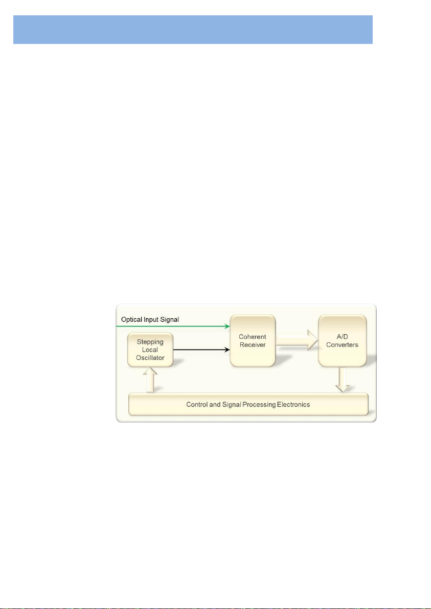
1.1 Operating principle
Unlike traditional OSA’s, the WaveAnalyzer 200A contains a
coherent receiver allowing extraordinary resolution in a
handheld device. A simplified block diagram of the
WaveAnalyzer 200A is shown in Figure 1-1.
Figure 1-1 Simplified WaveAnalyzer Block Diagram
The optical input is combined with a local oscillator in a coherent
receiver comprising a polarization-diverse optical mixer and two
pairs of balanced photo-detectors. The local oscillator is
stepped across the measurement wavelength range of interest,
and at each wavelength, the combined signals are then
converted from the optical domain into the electronic domain
using the balanced photo-detectors.

1-2
WaveAnalyzer 200A User Manual
Each of these electrical signals consists of three elements:
Intensitynoise
A DC element representing the power of the local
oscillator
The received signal
The baseband electrical signals are digitized by high-speed
analog to digital converters and the resulting digitized spectrum
is then displayed on the 7” touchscreen in the familiar
WaveAnalyzer software format, for direct analysis and
interrogation. Measurement data can be stored on a USB
Memory stick or uploaded to a computer for further analysis via
the in-built Ethernet port.

2-3
WaveAnalyzer 200A User Manual
Section 2 Getting Started
2.1 Safety considerations
The following general safety precautions must be observed
during all phases of operation, service and repair of this
instrument. Failure to comply with these precautions or with
specific warnings elsewhere in this document violates safety
standards of design, manufacture and intended use of the
instrument. Finisar assumes no liability arising from the failure
to comply with these requirements.
This product has been designed in accordance with IEC
Publication 61010-1, Safety Requirements for Electrical
Equipment for Measurement, Control and Laboratory Use, and
IEC Publication 60825-1 Safety of Laser Products - Part 1:
Equipment classification and requirements and has been
supplied in a safe condition. The instruction documentation
contains information and warnings that must be followed by the
user to ensure safe operation and to maintain the product in a
safe condition.
Before operation, review the instrument and manual for safety
markings and instructions. Follow these instructions to ensure
safe operation and to maintain the instrument in safe condition.
To avoid electrical shock, or possible battery fires, do not
operate the instrument if there are signs of structural damage to
any portion of the outer enclosure.
The instrument has been verified to conform to appropriate
safety specifications. Contact Finisar for details, if required.
WARNING
WARNIN
G
WARNIN

2-4
WaveAnalyzer 200A User Manual
2.2 Electrical safety
The WaveAnalyzer 200A includes an AC/DC power brick to
charge the unit’s 4 18650 Li-ion batteries. The adaptor requires
single phase AC power, 100-240 V, 50/60 Hz and provides
output DC power, 24V, 2.5A to the WaveAnalyzer 200A via a
standard P1J DC plug. Maximum power consumption is 60 VA.
The AC/DC switching adaptor has a C14 power inlet, and
requires a C13 power cable to connect the instrument to an
appropriate power socket (supplied), so that the cable earths
the supplied power brick.
To avoid the possibility of injury or death, observe the following
precautions before switching on the instrument.
Connect the power cable to a power outlet with a
protective earth contact
Do not negate this protective action by using an
extension cord or power block without a protective earth
conductor
Do not interrupt the protective earth connection
intentionally
Do not block or hinder access to the instrument power
inlet or power cable plug.
Do not open the instrument enclosure. The instrument
contains no user-serviceable components. Component
replacement and internal adjustments must be made
only by qualified Finisar service personnel
A WaveAnalyzer chassis that appears damaged or
defective should be made inoperative and secured
against unintended operation until it can be repaired by
qualified Finisar service personnel
A defective, damaged or malfunctioning WaveAnalyzer
must be returned to Finisar for repair. Please contact
Finisar before shipping any unit with mechanical
safe handling of a unit with possible Lithium Ion battery
damage.
WARNING
WARNIN
G
WARNIN
G
WARNIN
G
WARNIN

2-5
WaveAnalyzer 200A User Manual
2.3 Laser safety
The WaveAnalyzer 200A uses an internal Class 1M laser for
measurement purposes and is designed to not emit light from
the optical input.
The internal tunable laser is classified as Class 1M, per IEC
standard 60825-1 (2007-03). This product complies with
FDA/CDRH, 21 CFR 1040.10 and 1040.11 except for deviations
pursuant to Laser Notice No. 56, dated May, 2019.
CAUTION: Invisible Laser Radiation –Do not view directly with
optical instruments (magnifiers). In case of optical malfunction
within the instrument, laser power up to 20 mW at 1.55 μm could
be accessible. Viewing the laser output with certain optical
instruments, e.g. eye loupes, magnifiers and microscopes,
within a distance of 100 mm may pose an eye hazard. Use of
controls, adjustments, and procedures other than those
specified herein may result in hazardous laser radiation
exposure.
WARNING
WARNING
WARNING
WARNING
WARNING

2-6
WaveAnalyzer 200A User Manual
2.4 Unpacking and inspection
Before using the WaveAnalyzer 200A, please note the following
inspection requirements.
Inspect the instrument and shipping containers for
damage
Check that the package inventory is complete (see list
below)
Report any damaged or missing parts to a Finisar
representative
Retain the shipping containers and material until the
physical and operational condition of the instrument and
accessories are verified
The WaveAnalyzer 200A package contains the following items.
WaveAnalyzer 200A
1 x AC/DC switching adaptor with regional mains power
plugs
USB memory stick with Updater Tools and manual (this
document)
Certificate of Calibration
Quick Start Guide
Ethernet cable
2-7
WaveAnalyzer 200A User Manual
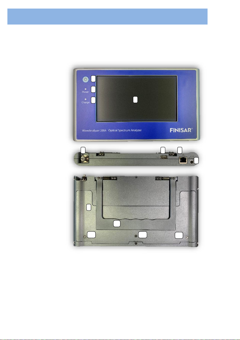
2.5 Ports and Mechanical Design
Figure 2-1 WaveAnalyzer 200A ports and mechanical design
1
2
3
4
Front
Top
5
6
7
8
9
10
11a
11b
11c
Back

2-8
WaveAnalyzer 200A User Manual
Table 1 WaveAnalyzer 200A Device Outline
No.
Item
Description
1
Power Button
Power button used to turn the device on
and off.
2
Power LED
Shines green to indicate that the device is
switched on.
3
Charge LED
Shines amber to indicate that the device
is currently on CHARGE.
4
Screen
The screen used to display the WA200A
interface.
5
Optical Port
The optical input port.
6
USB Port
Allows an external USB storage device to
be connected for easy transfer of
measurement data from the device to a
PC.
7
Ethernet Port
Allows the WaveAnalyzer 200A to be
remotely viewed and controlled over an
Ethernet interface.
8
Power Port
A 24V DC power port for charging.
9
Battery Plate
Cover
A removable plate allowing access to the
4 Lithium Ion batteries contained within
the unit. Note that the batteries can be
10
Handle/Stand
Used as a stand to keep the device
upright on a benchtop. May also be used
as a handle to hang the unit.
11
Battery Plate
Screws
Phillips screws 11a, 11b and 11c hold the
battery plate in place. They must be
removed in order to install/replace the Li-
Ion batteries. This should only be done by
authorized personnel.
2-9
WaveAnalyzer 200A User Manual
2.6 Start-up and initialization
To start the WaveAnalyzer 200A, press the power button on the
left of the front screen; the green front panel power switch light
indicates operational state. If requiring charging, the AC/DC
power adaptor can be plugged in; the orange front panel charge
switch light indicates the unit is charging.
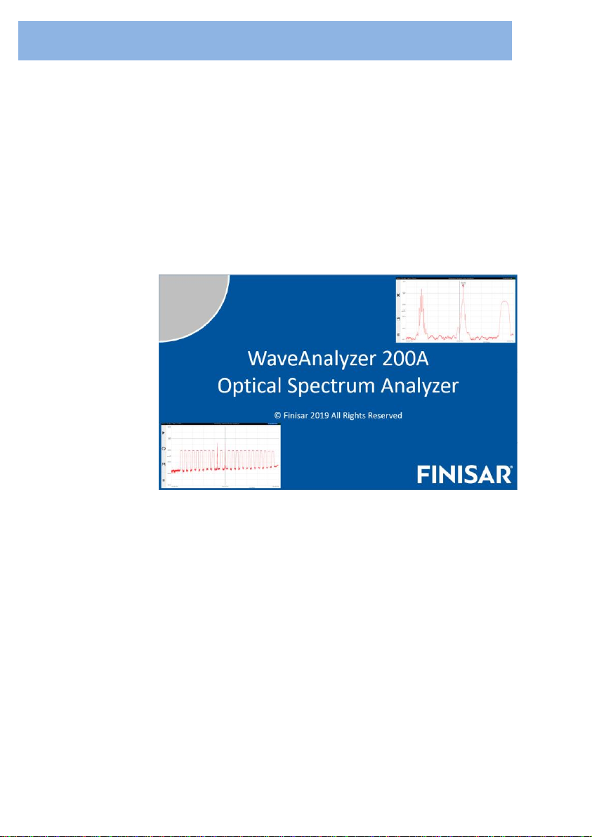
The WaveAnalyzer 200A has a 75 second power on phase.
During this time, the “Welcome Screen” is displayed.
Figure 2-2
WaveAnalyzer 200A Welcome Screen

2-10
WaveAnalyzer 200A User Manual
When the system is fully loaded, a blank “Work Screen” is
shown.
Figure 2-3
WaveAnalyzer 200A Work Screen
The “Status Bar” is located at the top of the Work Screen.
The “Grid” is located in the center of the Work Screen and
shows the current reading.
The “Button bar” is located on the left of the Work Screen.

2-11
WaveAnalyzer 200A User Manual
2.7 Connecting optical equipment
The WaveAnalyzer 200A contains sensitive optical
components, which may be damaged by excessive optical input
power. Optical input power must not exceed instrument
specifications.
Maintain proper cleanliness of optical interfaces. Connectors
should be cleaned with isopropyl alcohol and lint-free material,
or preferably with applicable connector cleaning cassette,
before connection.
2.8 Calibration, maintenance and service
The WaveAnalyzer 200A contains no user-serviceable
components. In the event of any fault occurring, the user should
contact Finisar or its representative for advice. Contact details
are listed at the end of this document. The WaveAnalyzer 200A
comes with a Certificate of Calibration.
This calibration date should be noted and the unit should be
returned to Finisar every 4 years for re-calibration. We also
recommend a general servicing of the instrument at this time.
This can include battery replacement, connector inspection and
replacement of damaged components if necessary.
WARNING
WARNING
WARNING
WARNING
WARNING
WARNING
WARNING
WARNING
WARNING

2-12
WaveAnalyzer 200A User Manual

3-13
WaveAnalyzer 200A User Manual
Section 3 Touchscreen interface
The WaveAnalyzer 200A presents measurement data directly
on the 7” touchscreen display.
3.1 The Status Bar
The left of the Status Bar shows the current total optical input
power, P(tot) and the selected resolution bandwidth. If
referencing is selected (as described in 3.5.1), REL is displayed.
If a hold mode is selected (as described in 3.5.1), the type of
hold will be displayed: MAX or MIN.
The right of the Status Bar shows the current date and the
battery status.
3.2 The Grid
The horizontal axis shows the frequency range (in THz or nm)
under the current “zoom” settings, with the frequency range per
division shown between the center and right labels.
To reset the view to the default trace, double tap the Grid.
Double tap again to zoom into the local maximum of the current
trace
The left vertical axis shows the power range (in dBm or mW)
under the current zoom settings, with power range per division
shown in the center of the axis.

3-14
WaveAnalyzer 200A User Manual
Zooming and Panning
To zoom into the Grid, users can pinch open by placing
the thumb and finger (or two fingers) close together on
the screen and move them apart without lifting from the
screen
To zoom out of the Grid, users can pinch close by
moving their fingers towards each other instead
To pan left, right, up or down users can place one
finger on the screen and move in a scrolling motion
accordingly
Zooming is possible simultaneously across both axes or
independently depending on the orientation used in the touch
motion.
Markers
To add a marker:
Use one finger, press and hold on the screen position.
A popup menu will appear
Tap on Add Marker to add a marker to that location
If you wish to accurately place the marker on a narrow
peak, magnify the trace until the peak fills the screen
To move a marker:
Tap and hold on a marker with one finger
Move your finger (left or right) to move the marker to a
new location
To delete a marker:
Press and hold one finger on the marker. A popup
menu will appear
Tap on the Delete Marker
3-15
WaveAnalyzer 200A User Manual
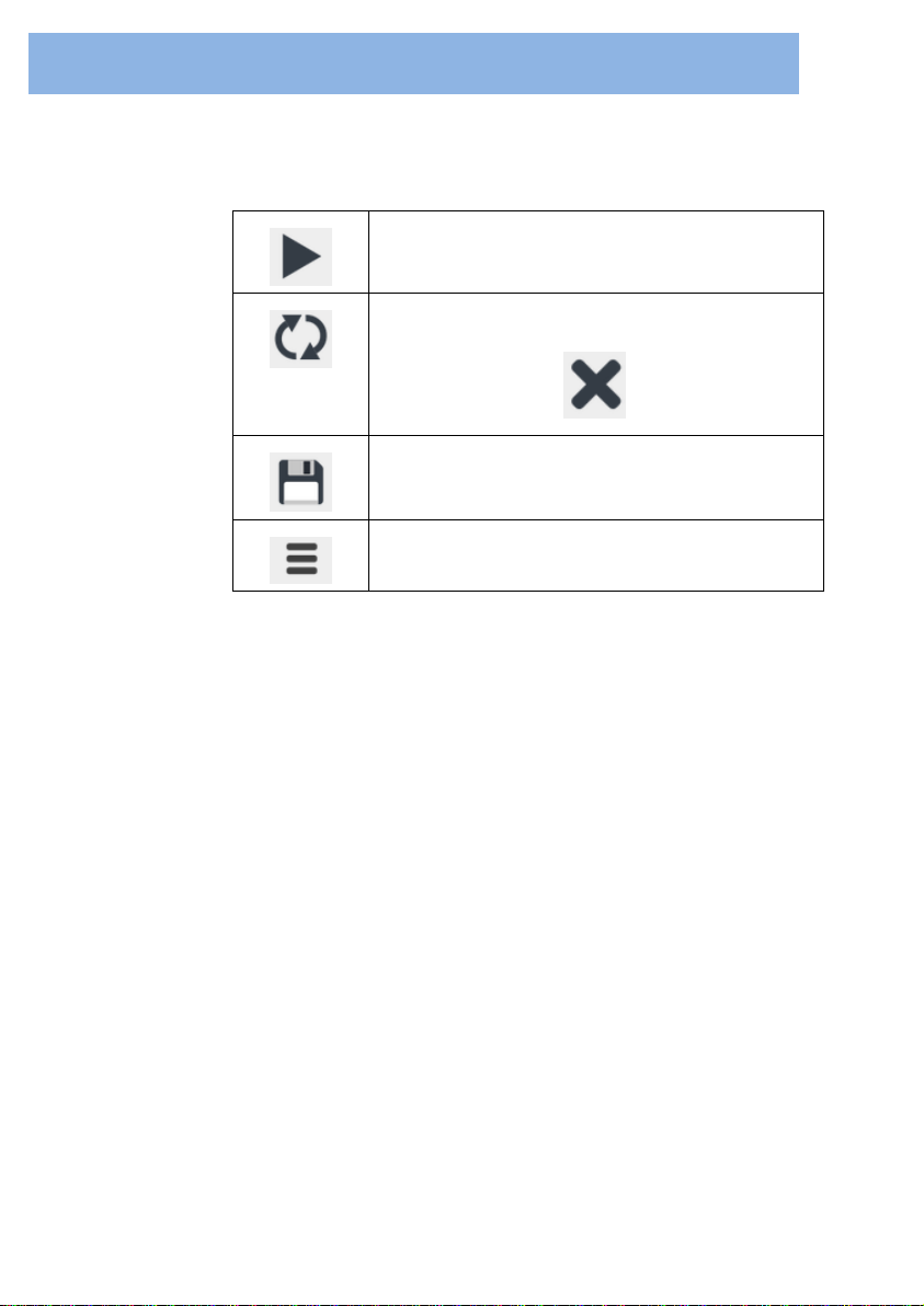
3.3 The Button Bar
Acquires and displays a single measurement
Continuously acquires and displays
measurements, until is pressed
Opens the “Files” menu
Opens the “Options” menu
Table of contents
Other Finisar Laboratory Equipment manuals

Popular Laboratory Equipment manuals by other brands


Visionix
Visionix Lensmeter VX36 Instructions for cleaning and sterilization

Terragene
Terragene Bionova MiniPro user manual

IKA
IKA IKAMAG RET control-visc C operating instructions

POL-EKO
POL-EKO SMART PRO ZLN 85 instruction manual

Biotage
Biotage V-10 Touch user manual

IKA
IKA Oven 125 control - dry glass operating instructions