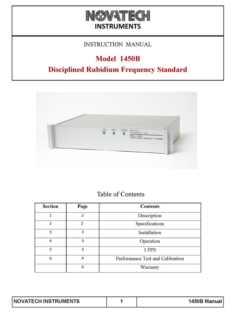
Novatech Instruments 2960AR User manual

NOVATECH INSTRUMENTS
1
2960AR/2965AR/2975AR Manual
INSTRUMENTS
Instruction Manual
Models 2960AR,2965AR and 2975AR
Disciplined Rubidium Frequency Standards
2960AR 2965AR
2975AR

2
2960AR/2965AR/2975AR Manual
1.0
DESCRIPTION
1.1 The Models 2960AR, 2965AR and 2975AR are
rubidium frequency standards which canbe
disciplined by an external 1pps (one pulse
per second) reference signal. This 1pps is
commonly derived from primary,or other
standards, such as GPS (global positioning
satellite). When disciplined to 1pps, these
instruments provide primary standard accuracy and
stability.
1.2 The 2960AR provides three fixed frequency
outputs of 10MHz(2) and 5MHz.The 2965AR and
2975AR replace one of the 10MHz outputs
with a programmable, 100Hz to 50MHz
synthesized output. The 2975AR adds a display
and manual controls for setting the synthesized
output frequency.The synthesized output is locked
to the internal rubidium oscillator and has the same
accuracy as the 10MHz and 5MHz outputs.
1.3 The most recent version of this manual can be
found on the Novatech Instruments web site.
2.0
SPECIFICATIONS (Typical)
2.1
FREQUENCY STABILITY (
∆
f/f)
Short Term: t=1s <3x10-11
t=10s <1x10-11
t=100s <3x10-12
Aging: Monthly <±5x10-11 after 1 month
Yearly <±5x10⁻¹⁰ after 3 months
Holdover (24Hours, ±2oC): <±1x10-11 (<±1µs after
>10x 1pps tracking time constant)
Temperature: +5 to +45oC <±1x10⁻¹⁰
Line Voltage: ±10% <±5x10-12
2.2
FREQUENCY ACCURACY
At shipment: <=±5x10-11 at 20oC.
Retrace: <=±5x10-11 from last frequency after
1hour ON and 24hours OFF (constant environment).
2.3 FIXED SINEWAVE OUTPUTS
10MHz and 5MHz, 1VRMS ±0.25VRMS into50Ω.
(10MHz, 10MHz and 5MHz for 2960AR)
NOVATECH INSTRUMENTS
2.4 SYNTHESIZED SINEWAVE OUTPUT
(2965AR and 2975AR only)
Frequency programmable from 100Hz to 50MHz in
1µHz steps.
Amplitude: 1VRMS±0.25VRMS at 5MHz into 50Ω
(±3dB from 100Hz to 50MHz, referenced to
10MHz).
Phase Noise:<-140dBc, 10kHz offset, 1MHz output.
Harmonics: <-45dBc, spurious: <-55dBc.
2.5 SPECTRAL PURITY (10MHz outputs)
Harmonic <-25dBc.
Spurious/Non-Harmonic/Sub-Harmonic: <-45dBc.
2.6 PHASE NOISE (Typical, 10MHz output, 50Ω)
Frequency Offset dBc
1Hz -70
10Hz -90
100Hz -120
1kHz -140
10kHz -140
2.7
1pps IN and OUT
1pps IN: DC-coupled, accepts TTL or CMOS. 1pps
OUT: TTL, 133µs negative pulse width. Typical
output jitter: 20ns peak-peak (1 minute measure-
ment time). (differential RS422 output optional)
2.8
ENVIRONMENTAL
Temperature: +0oC to +50oC operating.
Humidity: 80% to 31oC, decreasing linearly to
50% at 40oC.
2.9 SIZE
6.4cm H, 18.5cm W, 24.1cm L, excluding bail and
feet.
2.10 CONNECTORS
BNCs on front panel for sine outputs. BNCs on rear
panel for 1pps I/O. DE9 on rear panelfor
synthesizer RS232 serial interface (2965AR and
2975AR only). A serial cable is provided.
2.11 LINE POWER
120/240VAC ±10%, 50/60Hz. 30VA(50VA max
during warm up <20minutes).

3
2960AR/2965AR/2975AR Manual
2.12 FRONT PANEL INDICATOR LEDs
(2960AR and 2965AR only)
POWER OK: AC power is applied and on.
RUBIDIUM LOCK:Green: Oscillator is locked.
Red: Warm-up.
1 PPS LOCK: Locked to and tracking a 1pps input.
2.13 ACCESSORY
GPS1: Matching GPS smart antenna system.
3.0
INSTALLATION
WARNING:
The line power input connection is provided with a
3-wire cord. Do not defeat the grounded conductor.
3.1 Power Connection. Verify that the rear panel
indicates your line power (120VAC or 240VAC
50Hz/60Hz). Connect the provided 3-wire line cord
to your power source. The power switch is built-in
to the input module on the rear panel.
3.2 2960AR Installation. The 2960AR requires no
user setup beyond the application of line power and
connection to your application. Connect your 50Ω
coaxial cables to the appropriate front panel BNC.
See below for 1pps connections and use.
NOTE:
If you plan to use these instruments as part of a
calibration system or house standard, it is suggested
that they be powered from an uninterruptable power
supply (UPS) (along with your 1pps source, if used).
3.3 RS232 Installation (2965AR and 2975AR
only). Touse the internal synthesizer with the
RS232 serial interface, connect your host computer
to the 9-pin rear-panel connector with the provided
cable. Please note that the data TO is on pin 3; the
data FROM is on pin 2 and the COM-MONreturn
is on pin 5. Set your host to 19.2 kbaud, 8bits, 1
stop bit, no parity and no hardware flow control.
See Table 2 for RS232 Serial Commands.
A CD containing the SOF8_2965 windows software
program, that runs on windows operating systems
through windows 10, is included with the 2965AR
and 2975AR instruments.
NOVATECH INSTRUMENTS
3.5 The command ‘Qr’ returns the values in the
volatile RAM of the instrument. The values
returned reflect the present output and state of the
synthesizer and are as follows:
F 12.345678901234
45 06 03 1B 05 00 00 02
3.6 The first line shows the output frequency in MHz
to 1µHz resolution. All twelve digits are always sent.
The next line has hexadecimal values showing the
present state of internal registers. These values will
only be the same as those from the ‘Qe’ command if
the values have been unchanged or a ‘S’ command
has been executed. They are reserved for factory use.
3.7 The command ‘Qe’ returns the stored values in
the non-volatile EEPROM of the instrument. The
values returned reflect the last saved state of the
synthesizer and are as follows:
F 12.345678901234
45 06 03 1B 05 00 00 02 00 EF FF B7 01
3.8 The first line shows the output frequency in MHz
to 1µHz resolution. The next line has hexadecimal val-
NOTE:
The 2965AR and 2975AR are provided with a 2 meter
RS232 cable. If you use a different cable, please note
that a male-to-female, straight-through connection is
required. Only pins 2, 3 and 5 are used.
3.4 The serial commands are not case sensitive.
There must be a space after each command except R,
C,S, Qr and Qe. End with any combination of
CR, LF or CRLF. Received commands result in a
response code being returned per Table 1. Codes
beginning with a ‘?’ indicate illegal or unrecog-
nized commands.
Table 1: RS232 Response Codes
Repsonse
Code
Meaning
OK Good command received (not sent for
Reset, C, Qr and Qe)
?0 Unrecognized Command
?1 Bad Frequency
?3 Input line too long

NOVATECH INSTRUMENTS
4
2960AR/2965AR/2975AR Manual
Table 2: Synthesizer RS232 Serial Commands (2965AR and 2975AR only)
Serial Command
Function
F xx.xxxxxxxxxxxx Set Frequency in MHz to nearest 1µHz. Decimal point required.
E x Serial Echo Control. x=D for Echo
D
isable, x=E for Echo
E
nable. Default
is
E
nabled.
SSave current state into EEPROM and sets valid flag. State saved is used as
default upon next power up or reset.
Reset Reset. This command resets the instrument. EEPROM data is preserved
and, if valid, it is used upon restart. (The command ‘R’ also performs this
function.)
RbR Reset the Rubidium Oscillator. This sets the internal Rubidium settings to
the last internally saved values. Does not affect the synthesizer output.
Restarts 1pps tracking time.
CClear. This command clears the EEPROM valid flag and restores all
factory default values (5MHz output).
Qr Query the volatile (RAM) memory storage. These are the values currently
output by the synthesizer. These will equal the stored values in the
EEPROM after a ‘Reset’ or power up only if no changes have been
made in the settings.
Qe Query the non-volatile memory (EEPROM) storage.

5
2960AR/2965AR/2975AR Manual
ues showing the saved state of internal registers. These
are for factory use.
3.9 Signal Outputs. The 2960AR has three front
panel outputs of 10MHz(2) and 5MHz. Each has a
nominal amplitude of 1Vrms into 50Ω. The 2965AR
and 2975AR have three front panel outputs of
10MHz, 5MHz and a 100Hz to 50MHz synthesized
output. Each has an amplitude of 1Vrms into 50Ω.
3.10 See section 5.0 for the rear panel 1pps IN and
OUT characteristics and use.
4.0
Operation
4.1 Power on. After power is applied, the 2960AR
and 2965AR POWER OK LED will be green.
This indicates that the applied line power is within
tolerance and the unit is functioning. The 2975AR
will display the software version for 5 seconds and
then switch to indicating warm up mode.
4.2 Rubidium Warm-up. After power is applied,
it will take up to 20 minutes to reach Rubidium
Lock. After the warm up period the Rubidium
Lock LED will change from red to green
on the 2960AR and 2965AR and the 2975AR will
display the synthesized frequency setting.
NOTE:
During the Rubidium locking process, the front
panel RUBIDIUM LOCK LED may switch between
red and green. A steady green indicates LOCK.
4.3 Proper operation, without a 1pps connection, is
indicated by agreen POWER OK LED and a
green RUBIDIUM LOCK LED with the 1pps
LED off (2960AR and 2965AR) or, dashes on the
second line of the 2975AR display.
NOTE:
The specified accuracy will be met within a few
hours after power-up. For applications requiring
verification of long-term stability, the periods shown
in the specifications will have to be met.
4.4 See the section “1pps Operation,” below,for
details on 1pps connections and operation.
4.5 Serial control of Synthesizer The user host
computer software must properly format the serial
commands. Incorrect formatting will result in an
error code being returned. See Table 1 on page 3
for a list of RS232 error codes.
4.6 For maximum interface speed, it is suggested
that Echoing be disabled by the “E D” command.
This will allow the host to send characters at a
faster rate. Flow control must be provided by
the host. The 2965AR and 2975AR will respond
with an “OK” for acorrectly received data
command. If your host software parses this “OK”,
you will be assured that the command has been
correctly received and you may send your next
command. You will have to verify correct operation
at your host rate.
5.0
1pps Operation
5.1 1pps In and Out. There are rear panel
BNC receptacles which accept a 1pps input and
provide a 1pps output. Use of 1pps allows
synchronization of multiple units, as well as
providing a means of auto-calibration.
5.2 A long-term stable 1pps signal is typically
derived from a GPS (global positioning system)
receiver or from another frequency standard. Both
units will autoadapt to the supplied 1pps and
adjust the internal Rubidium Oscillator to match
the long term average frequency derived from the
1pps. The auto-adaptive algorithm selects the best
tuning time constant based upon the stability of your
supplied 1pps.
5.3 For low-jitter 1pps inputs (<20ns), the approxi-
mate tuning time constant will be 1,000 seconds. A
typical timing receiver system, such as the GPS1
(with approximately 100ns peak-peak 1pps jitter),
requires a time constant of approximately 10,000
seconds (about 3 hours) for optimum tracking.
5.4 For noisier 1pps inputs, such as those from
standard GPS receivers not intended for timing
applications, the time constant may increase to
100,000 seconds. If the input is too noisy, as
determined by the auto-adaptive algorithm, the 1
PPS LOCK light will not illuminate.
NOVATECH INSTRUMENTS

6
2960AR/2965AR/2975AR Manual
5.5 Proper operation when tracking a 1pps signal
is indicated when all three front panel LEDs
are illuminated green on the 2960AR and 2965AR
and when the bottom line on the display shows
"Tracking 1pps" on the 2975AR.
NOTE:
Due to these long time constants necessary to track
a 1pps input, temperature variations can cause
fluctuations in the relative phase of the 10MHz
output and the 1pps output.
NOTE:
The
∆
f/f tracking range of the internal Rubidium
oscillator is approximately ±1x10⁻⁸. If your 1pps
source is in error,but within these limits, the
2960AR/2965AR/2975AR will adjust to your source.
This allows multiple units to by synchronized even in
the absence of an absolute reference.
CAUTION:
Do not connect the 1pps input and 1pps output on an
instrument together. This will force the instrument to
track a moving value and reach its adjustment limit.
5.6 These instruments are configured for
automatic self calibration. When continuously
connected to a stable 1pps source, they will
autosave the disciplined frequency value into
non-volatile calibration memory every 24 hours.
The last-saved value will be used at next power on
or when 1pps is lost. The 1pps output of a
calibrated and tracking instrument has lower
jitter than a typical GPS receiver making it
suitable for use as amaster oscillator for further
1pps systems.
6.0
PERFORMANCE TEST
6.1 The performance test detailed below verifies the
functions of the 2960AR, 2965AR and the 2975AR.
NOTE:
Verification of the frequency and frequency stability
requires a laboratory environment of 23oC ±5oC.
NOVATECH INSTRUMENTS
6.2 See Table 3 for a list of recommended test
equipment to perform the following measurements.
6.3 Verify Frequency Accuracy.To verify the fre-
quency, set the frequency counter to display 12-
digits of resolution. The frequency counter must
use an external time base of accuracy better than
±1x10-11.
6.4 Verify the correct frequency at each 5MHz and
10MHz output.For the 2965AR and 2975AR,also
verify the synchronized output at the frequencies in
Table 4). Allow the counter to average several
readings. See Table 4 for frequency error limits.
6.5 Amplitude Verification. Establish ameasure-
ment function of Volts RMS on the oscilloscope.
Connect a50Ωcoaxial cable from the 2960AR,
2965AR or 2975AR to the oscilloscope (set to 50Ω
termination) Verify an amplitude of 1.0Vrms
±0.25Vrms on each output.
6.6Output Flatness Verification. (Synthesized
output only). Set the 2965AR or 2975AR to the
values of Table 4. Measure the Vrms value of the
outputs with an oscilloscope. Verify that the
readings are within the tolerances shown.
Table 3: Recommended Test Equipment
Item
Minimum
Specification
Recommended
Oscilloscope 300MHz, 50Ω
termination Tektronix
Frequency
Counter 100MHz, 12-
digits.
Counter Time
Base <±1x10-11
TDS3032B
HP53132A
Novatech
Instruments
Model 2965AR
with GPS1 smart
antenna.

7
2960AR/2965AR/2975AR Manual
6.9 This concludes the verification test.
7.0
CALIBRATION
7.1 The 2960AR, 2965AR and 2975AR require
no routine adjustments for typical operation.
NOTE:
When necessary, calibration should be performed
“closed-case” using an external 1pps source.
7.2 Closed-case calibration is obtained by connect-
ing the instrument to a known stable and accurate
1pps source, such as a GPS1. (Faster tracking is
obtained by using the 1pps output of a2960AR or
a 2965AR or a 2975AR that is already tracking
and stabilized to a 1pps input source.)
7.3 Verify that the 1 PPS TRACKING light illumi-
nates green (2960AR and 2965AR) or that the
second line on the dispay annunciates "Tracking
1pps" (2975AR). A stable 1pps source will allow this
within 15 minutes after connection.
7.4 Leave the unit tracking the 1pps in a stable envi-
ronment for a minimum of 5 days. During this time,
the internal auto-adaptive algorithm will measure
and qualify the 1pps source,adjusting the frequency
to the long term average of the 1pps source.
7.5 Best calibration performance is obtained in an
environment stable to 23oC ±3oCor better.
NOTE:
The auto-adaptive frequency adjustment has a
resolution of ±5.12x10⁻¹³.
NOVATECH INSTRUMENTS
7.6 Whenever possible, the 2960AR, 2965AR
and 2975AR should remain connected to a stable
1pps source. Longer calibration periods are
indicated for obtaining maximum performance.
Table 4:Frequency Test Points
Frequency
∆
f
Tolerance
100kHz ±5µHz 1.0Vrms±0.25Vrms
1MHz ±50µHz 1.0Vrms±0.25Vrms
5MHz ±250µHz 1.0Vrms±0.25Vrms
10MHz ±500µHz 1.0Vrms±0.25Vrms
30MHz ±1.5mHz 1.0Vrms±0.5Vrms
50MHz ±2.5mHz 1.0Vrms±0.5Vrms

NOVATECH INSTRUMENTS
8
2960AR/2965AR/2975AR Manual
WARRANTY
NOVATECH INSTRUMENTS warrants that all instruments it manufactures are free from defects in
material and workmanship and agrees to replace or repair any instrument found defective during a
period of one year from date of shipment to original purchaser.
This warranty is limited to replacing or repairing defective instruments that have been returned by
purchaser, at the purchaser's expense, to NOVATECH INSTRUMENTS and that have not been
subjected to misuse, neglect, improper installation, repair alteration or accident. NOVATECH
INSTRUMENTS shall have the sole right to final determination regarding the existence and cause of a
defect.
This warranty is in lieu of any other warranty, either expressed or implied, including but not limited to
any warranty of merchantability or fitness for a particular purpose. In no event shall seller be liable for
collateral or consequential damages. Some states do not allow limitations or exclusion of consequential
damages so this limitation may not apply to you.
All instruments manufactured by NOVATECH INSTRUMENTS should be inspected as soon as they
are received by the purchaser. If an instrument is damaged in shipment the purchaser should
immediately file a claim with the transportation company. Any instrument returned to NOVATECH
INSTRUMENTS should be shipped in its original shipping container or other rigid container and
supported with adequate shock absorbing material.
This warranty constitutes the full understanding between NOVATECH INSTRUMENTS and the
purchaser and no agreement extending or modifying it will be binding on NOVATECH
INSTRUMENTS unless made in writing and signed by an authorized official of NOVATECH
INSTRUMENTS.
NOVATECH INSTRUMENTS
United States of America
206.301.8986 Voice
http://www.novatechsales.com/
sales@novatechsales.com
This manual suits for next models
2
Table of contents
Other Novatech Instruments Laboratory Equipment manuals
