Finisar WaveShaper A Series User manual

WaveShaper A-Series User Manual
WaveShaper A Series User Manual
1

Revision A00
The WaveShaper Help covers the general operation of the WaveShaper Series 'A' products and the WaveShaper 1.4 software
package which includes the WaveShaper App and the WaveShaper Webserver.
It is not valid for other hardware or software versions.
For information about the WaveShaper Series 'A' range, please visit the Finisar Optical Instrumentation website.
For detailed technical help, please visit the Finisar KnowledgeBase website. (www.finisarknowledgebase.com)
© Finisar 2013 – 2020
WaveShaper A Series User Manual
2

Contents
Section 1 Overview
. . . . . . . . . . . . . . . . . . . . . . . . . . . . . . . . . . . . . . . . . . . . . . . . . . . . . . . . . . . . . . . . . . . . . . . . . . . . . . . . . . . . .
4
1.1 Safety Considerations
. . . . . . . . . . . . . . . . . . . . . . . . . . . . . . . . . . . . . . . . . . . . . . . . . . . . . . . . . . . . . . . . . . . . . . . . . . .
4
1.2 LCoS Introduction
. . . . . . . . . . . . . . . . . . . . . . . . . . . . . . . . . . . . . . . . . . . . . . . . . . . . . . . . . . . . . . . . . . . . . . . . . . . . . .
5
1.3 Optical Design
. . . . . . . . . . . . . . . . . . . . . . . . . . . . . . . . . . . . . . . . . . . . . . . . . . . . . . . . . . . . . . . . . . . . . . . . . . . . . . . . .
5
Section 2 Connecting via Ethernet
......................................................................
6
2.1 Connecting to the Waveshaper
. . . . . . . . . . . . . . . . . . . . . . . . . . . . . . . . . . . . . . . . . . . . . . . . . . . . . . . . . . . . . . . . . . .
6
2.2 Ethernet Connection
. . . . . . . . . . . . . . . . . . . . . . . . . . . . . . . . . . . . . . . . . . . . . . . . . . . . . . . . . . . . . . . . . . . . . . . . . . . .
6
2.3 Webserver Browser Interface
. . . . . . . . . . . . . . . . . . . . . . . . . . . . . . . . . . . . . . . . . . . . . . . . . . . . . . . . . . . . . . . . . . . . .
7
2.4 Can't find the WaveShaper?
. . . . . . . . . . . . . . . . . . . . . . . . . . . . . . . . . . . . . . . . . . . . . . . . . . . . . . . . . . . . . . . . . . . . . .
8
2.5 WaveShaper Mac Address
. . . . . . . . . . . . . . . . . . . . . . . . . . . . . . . . . . . . . . . . . . . . . . . . . . . . . . . . . . . . . . . . . . . . . . .
8
Section 3 Graphical User Interface
......................................................................
9
3.1 Filter
. . . . . . . . . . . . . . . . . . . . . . . . . . . . . . . . . . . . . . . . . . . . . . . . . . . . . . . . . . . . . . . . . . . . . . . . . . . . . . . . . . . . . . . . . .
9
3.6 Sketch
. . . . . . . . . . . . . . . . . . . . . . . . . . . . . . . . . . . . . . . . . . . . . . . . . . . . . . . . . . . . . . . . . . . . . . . . . . . . . . . . . . . . . . . .
13
3.12 Pulse Shaping
. . . . . . . . . . . . . . . . . . . . . . . . . . . . . . . . . . . . . . . . . . . . . . . . . . . . . . . . . . . . . . . . . . . . . . . . . . . . . . . . .
20
3.17 Tools
. . . . . . . . . . . . . . . . . . . . . . . . . . . . . . . . . . . . . . . . . . . . . . . . . . . . . . . . . . . . . . . . . . . . . . . . . . . . . . . . . . . . . . . . .
24
3.24 Power Splitting
. . . . . . . . . . . . . . . . . . . . . . . . . . . . . . . . . . . . . . . . . . . . . . . . . . . . . . . . . . . . . . . . . . . . . . . . . . . . . . . .
28
Section 4 Defining Optical Filters
......................................................................
30
4.1 Optical Filter Files
. . . . . . . . . . . . . . . . . . . . . . . . . . . . . . . . . . . . . . . . . . . . . . . . . . . . . . . . . . . . . . . . . . . . . . . . . . . . . .
30
4.2 User Configured Filters (*.ucf)
. . . . . . . . . . . . . . . . . . . . . . . . . . . . . . . . . . . . . . . . . . . . . . . . . . . . . . . . . . . . . . . . . . .
30
4.3 WaveShaper Presets (*.wsp)
. . . . . . . . . . . . . . . . . . . . . . . . . . . . . . . . . . . . . . . . . . . . . . . . . . . . . . . . . . . . . . . . . . . . .
31
Section 5 Programming
. . . . . . . . . . . . . . . . . . . . . . . . . . . . . . . . . . . . . . . . . . . . . . . . . . . . . . . . . . . . . . . . . . . . . . . . . . . . . . .
35
5.1 RESTful Interface
. . . . . . . . . . . . . . . . . . . . . . . . . . . . . . . . . . . . . . . . . . . . . . . . . . . . . . . . . . . . . . . . . . . . . . . . . . . . . .
35
5.2 HTTP API Basics
. . . . . . . . . . . . . . . . . . . . . . . . . . . . . . . . . . . . . . . . . . . . . . . . . . . . . . . . . . . . . . . . . . . . . . . . . . . . . . . .
36
5.3 Programming Examples
. . . . . . . . . . . . . . . . . . . . . . . . . . . . . . . . . . . . . . . . . . . . . . . . . . . . . . . . . . . . . . . . . . . . . . . .
37
5.4 Python Examples
. . . . . . . . . . . . . . . . . . . . . . . . . . . . . . . . . . . . . . . . . . . . . . . . . . . . . . . . . . . . . . . . . . . . . . . . . . . . . .
38
5.5 MATLAB Examples
. . . . . . . . . . . . . . . . . . . . . . . . . . . . . . . . . . . . . . . . . . . . . . . . . . . . . . . . . . . . . . . . . . . . . . . . . . . . .
39
5.6 LabVIEW Examples
. . . . . . . . . . . . . . . . . . . . . . . . . . . . . . . . . . . . . . . . . . . . . . . . . . . . . . . . . . . . . . . . . . . . . . . . . . . . .
41
5.7 Power Splitting Programming
. . . . . . . . . . . . . . . . . . . . . . . . . . . . . . . . . . . . . . . . . . . . . . . . . . . . . . . . . . . . . . . . . . .
42
Section 6 Specifications
...............................................................................
44
6.1 Optical Specifications
. . . . . . . . . . . . . . . . . . . . . . . . . . . . . . . . . . . . . . . . . . . . . . . . . . . . . . . . . . . . . . . . . . . . . . . . . .
44
6.2 Electrical Specifications
. . . . . . . . . . . . . . . . . . . . . . . . . . . . . . . . . . . . . . . . . . . . . . . . . . . . . . . . . . . . . . . . . . . . . . . . .
45
6.3 Environmental Conditions
. . . . . . . . . . . . . . . . . . . . . . . . . . . . . . . . . . . . . . . . . . . . . . . . . . . . . . . . . . . . . . . . . . . . . .
46
WaveShaper A Series User Manual
3

Section 1 Overview
1.1 Safety Considerations
The following general safety precautions must be observed during all phases of operation, service, and repair of this module.
Failure to comply with these precautions or with specific warnings elsewhere in this manual violates safety standards of design,
manufacture, and intended use of the instrument. Finisar assumes no liability for the failure to comply with these requirements.
This product has been designed in accordance with IEC Publication 61010-1, Safety Requirements for Electrical Equipment for
Measurement, Control and Laboratory Use, and IEC Publication 60825-1 Safety of Laser Products - Part 1: Equipment classification
and requirements and has been supplied in a safe condition. This documentation contains information and warnings that must be
followed by the user to ensure safe operation and to maintain the product in a safe condition. Before operation, you should review
the instrument and manual for safety markings and instructions. You must follow these to ensure safe operation and to maintain
the instrument in safe condition.
To avoid electrical shock, do not perform electrical tests when there are signs of shipping damage to any portion of the outer
enclosure.
Laser Safety
The WaveShaper family of Programmable Optical Processors are designed for use with various classes of laser up to, and including,
Class 3B lasers. Whilst the WaveShaper module does not generate laser light, laser light may be present on one or more output
ports depending on the configuration of WaveShaper selected and the type of laser connected to the input port(s). Please pay
attention to the following laser safety warnings:
Under no circumstances look into the end of an optical output cable/connector(s) when the device is operational. If
there is any laser radiation it could seriously damage your eyesight.
Do not operate the WaveShaper without attaching the optical output connector(s) to a safely terminated mating
connector(s).
Refer servicing only to qualified and authorized Finisar personnel.
Electrical Safety
The mains-powered versions of the WaveShaper require single-phase AC, 100–240V, 50–60Hz and has a maximum power
consumption of 50VA. In accordance with international safety standards, the instrument has a three-wire power cable. When
connected to an appropriate AC power receptacle, this cable earths the instrument chassis. To avoid the possibility of injury or
death, you must observe the following precautions before switching on the instrument.
Insert the power cable plug only into a socket outlet provided with a protective earth contact. Do not negate this
protective action by using an extension cord or power block without a protective conductor.
Do not interrupt the protective earth connection intentionally.
Do not remove protective covers. Operating personnel must not remove instrument covers. The unit contains no user-
serviceable components. Component replacement and internal adjustments must be made only by qualified Finisar
service personnel.
A WaveShaper chassis that appears damaged or defective should be made inoperative and secured against unintended
operation until it can be repaired by qualified Finisar service personnel.
A defective, damaged, or malfunctioning WaveShaper chassis must be returned to Finisar for repair.
The module versions of the WaveShaper are designed to operate from a user-supplied +5V supply.
The module contains Electrostatic Discharge Sensitive Devices.
Operating personnel must not remove the module lid. The module contains no user-serviceable components.
Component replacement and internal adjustments must be made only by qualified Finisar service personnel.
A WaveShaper module that appears damaged or defective should be made inoperative and secured against unintended
operation until it can be repaired by qualified Finisar service personnel.
WaveShaper A Series User Manual
4
The module is supplied with a mating Phoenix power plug which needs to be wired to a power supply capable of providing +5V to
+5.6V at a current of at least 8A. The wire used should be red for +5V and black for 0V 22AWG (0.5mm,16/0.2,Tri-rated PVC
insulated UL1015).
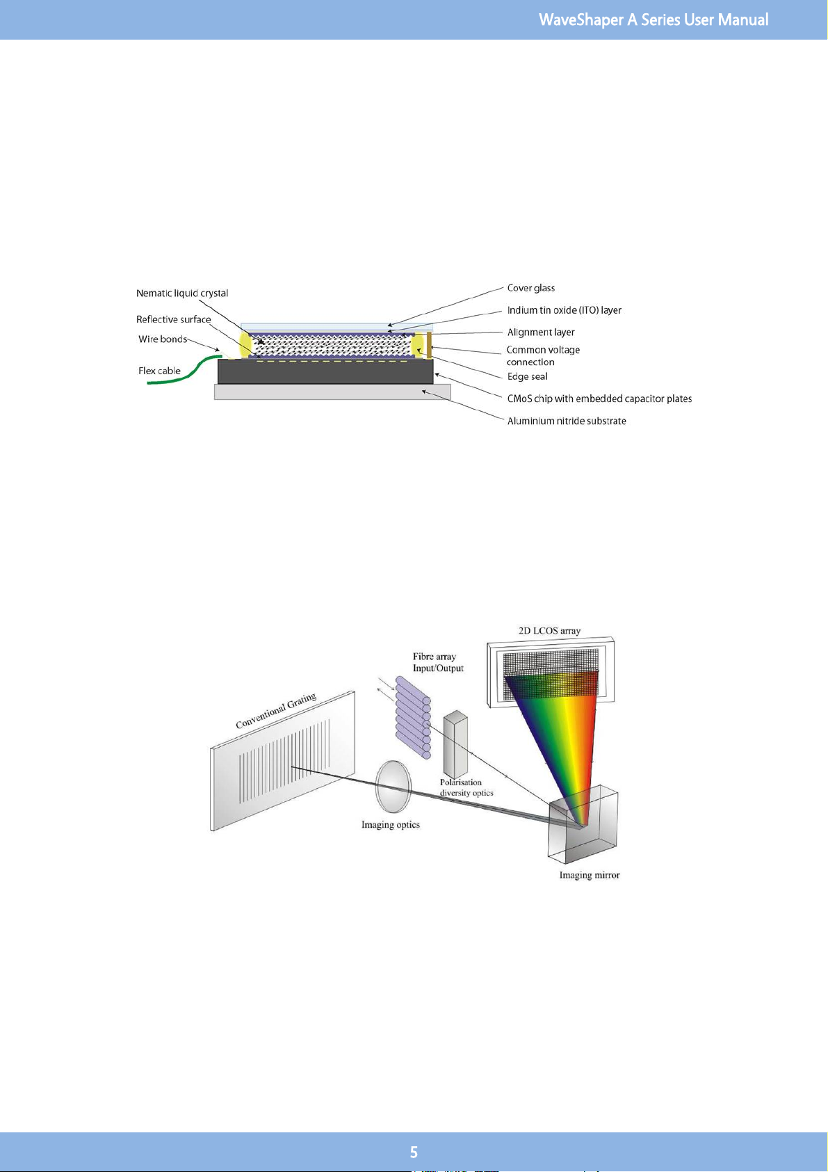
1.2 LCoS Introduction
Conventional liquid crystal components used in telecom applications employ control of polarisation state to pass or transmit light
to create for example wavelength blockers or attenuators. Switching applications can be achieved through polarisation dependent
deflection or displacement. These designs are limited by having inflexible configurations – typically with one pixel per channel -
and the requirement to preconfigure the channel plan in advance.
Liquid Crystal on Silicon (LCoS) is a display technology which combines Liquid Crystal and semiconductor technologies, to create
a high resolution, solid-state display engine. The diagram shows the structure of an LCoS display with the Liquid Crystal (LC) layer
sandwiched between the Active Matrix silicon backplane and the ITO-coated (Indium Titanium Oxide) top glass.
1.3 Optical Design
LCoS can be employed to control the phase of light at each pixel to produce beam steering. In the WaveShaper, a large number of
phase steps are used to create a highly efficient, low-insertion loss switch shown schematically in this diagram. This simple optical
design incorporates polarisation diversity, control of mode size and a 4-f wavelength optical imaging in the dispersive axis of the
LCoS providing integrated switching and optical power control.
Light enters the device from a fibre array, and is then processed by polarisation diversity optics to align orthogonal polarisation
states to maximize efficiency at the diffraction grating. The grating is designed to be at Littrow incidence, and angularly disperses
the light to the LCoS array, where the reflected light is traced back through the system to the chosen output fibre, based on the
beam-steering image programmed on the LCoS array.
As the wavelengths are separated on the LCoS the control of each wavelength is independent of all others and can be switched or
filtered without interfering with other wavelengths.
WaveShaper A Series User Manual
5
Section 2 Connecting via Ethernet
2.1 Connecting to the Waveshaper
Connection to multiple Series A WaveShapers can be made through a LAN or Internet connection where each WaveShaper is
addressed by a unique IP address. The connection is through http commands which make the control interface platform
independent. Windows, OS X, Android, iOS, Linux, etc...are all supported.
All Series A WaveShapers can be controlled through one of four techniques:
WaveShaper App Graphical User Interface (Ethernet only)
RESTful HTTP Commands (Ethernet Only)
WaveManager 2.7.4 and above (USB only, backward compatible)
WaveShaper API (USB only, backward compatible)
This help document covers the WaveShaper App and RESTful HTTP Commands - for details on the WaveManager 2.7 and API,
please see the relevant documentation on the Finisar website.
2.2 Ethernet Connection
There are two programs used to connect to the WaveShaper through the Ethernet port. The WaveShaper App is installed on
Windows operating systems and the WaveShaper Webserver is installed on each Series 'A' WaveShaper for control through HTTP.
Note that the App and Webserver are identical and vary only in the location that they are stored. The functionality for both is
identical.
WaveShaper App
The WaveShaper App is a Windows program that will run on Windows 7, 8.1 and 10 systems. It can be installed from the USB drive
that is supplied with the WaveShaper or it can be downloaded from the Finisar website.
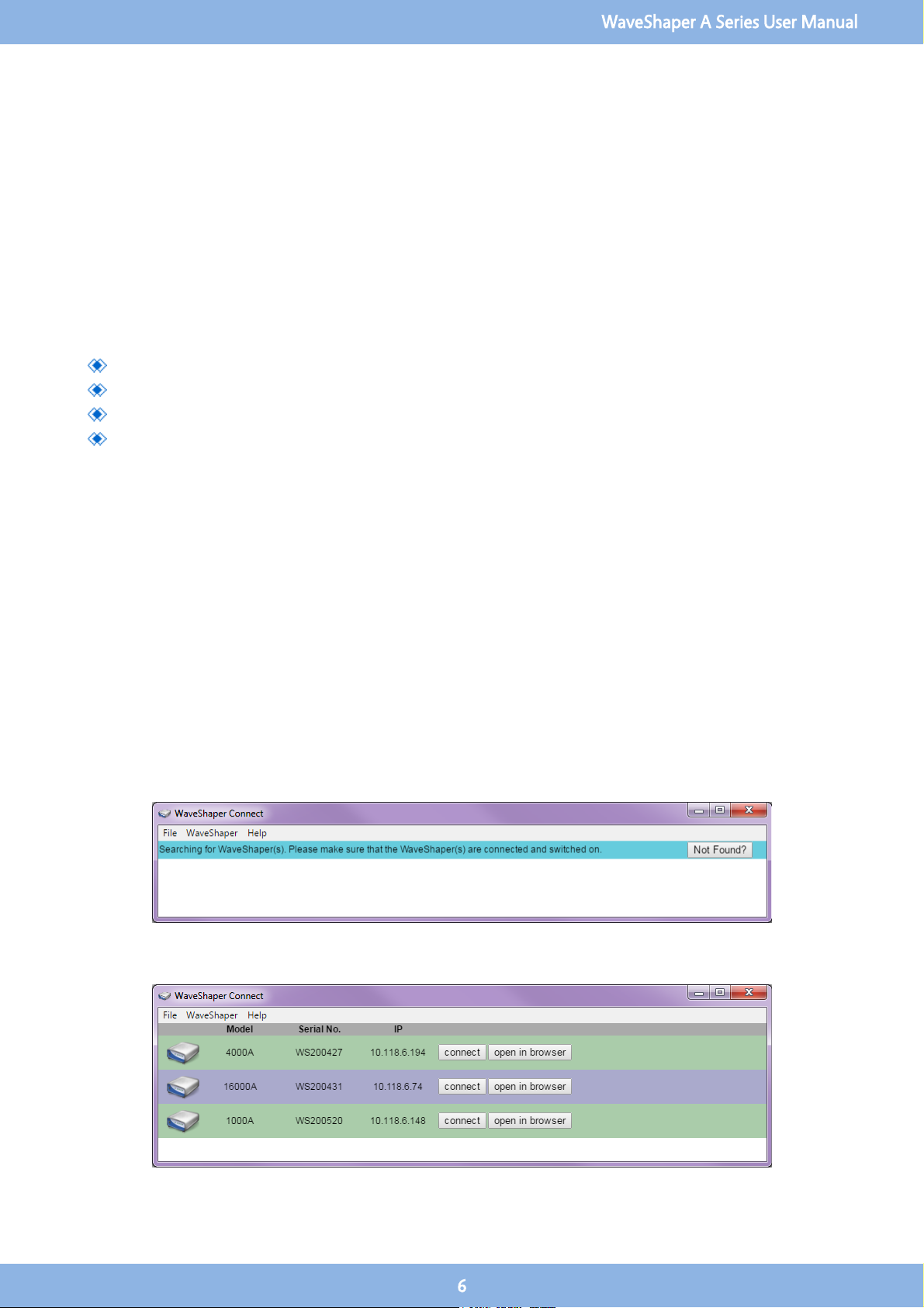
When the program is run, the WaveShaper Connect window will open and run a search for any WaveShapers connected to the
network.
It will then show a list of WaveShapers currently connected to the network. The information shown will be the WaveShaper model
number, serial number and IP address.
WaveShaper A Series User Manual
6
The "connect" button will open up the WaveShaper App which is a program built using HTML5 and JavaScript.
The "open in browser" button will connect to the webserver on the WaveShaper and it will open in the default web browser
installed on the computer.
The WaveShaper App must be used to install any WaveShaper Firmware updates that may be required through the Tools option.
WaveShaper Not Found?
If the WaveShaper connected to the network does not appear then the "Not Found?" button will connect you to the connection
troubleshooting section of the help file.
WaveShaper Connect Menu Options
The WaveShaper Connect contains a number of menu options.
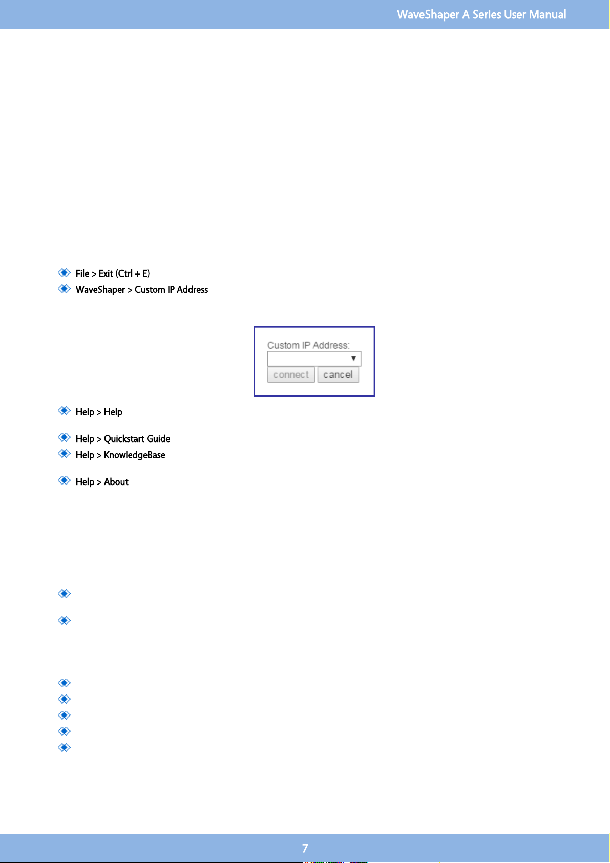
File > Exit (Ctrl + E): Shortcut to exit the WaveShaper Connect program.
WaveShaper > Custom IP Address: Used to connect to a WaveShaper on the network that has a fixed IP address and is
not discoverable through the WaveShaper Connect program. Type the IP address into the window then click on the
connect button.
Help > Help: Connects to a standalone help window showing the contents of the help file, without the icon ribbon of
the WaveShaper App.
Help > Quickstart Guide: Opens up a PDF version of the Quickstart Guide shipped with the WaveShaper.
Help > KnowledgeBase: Connects to an online address that is dedicated to answering more technical questions about
the WaveShaper and WaveAnalyzer family of products from the Optical Instrumentation Group of Finisar.
Help > About: Shows the currently installed version number of the WaverShaper App.
2.3 Webserver Browser Interface
The WaveShaper Series A instruments contain an in-built webserver. Any operating system with a Web Browser can connect to the
WaveShaper directly by sending HTTP commands directly to the unit. No dedicated software or drivers are required.
There are two addresses that can be used to connect to the WaveShaper.
mDNS address: for example WS200427.local where the WS200427 is the serial number of the WaveShaper. Once
connected, the IP address will appear in the address bar: http://ws200427.local/waveshaper.html#/basic
IP address: for example typing 10.118.6.194 directly into the address bar. The IP address can be obtained by using the
WaveShaper Connect program found when installing the WaveShaper App. Once connected, the IP address will appear
in the address bar: http://10.118.6.194/waveshaper.html#/basic
The WaveShaper Webserver can be used in conjunction with the following browsers:
Firefox
Chrome
Safari
Internet Explorer version 11 and above
Microsoft Edge
WaveShaper A Series User Manual
7
The WaveShaper can be controlled using the web browser on a hand-held device such as a tablet or phone. However, performance
has been optimised for use with a mouse and keyboard and not all functions may operate correctly when used with a touchscreen
device.
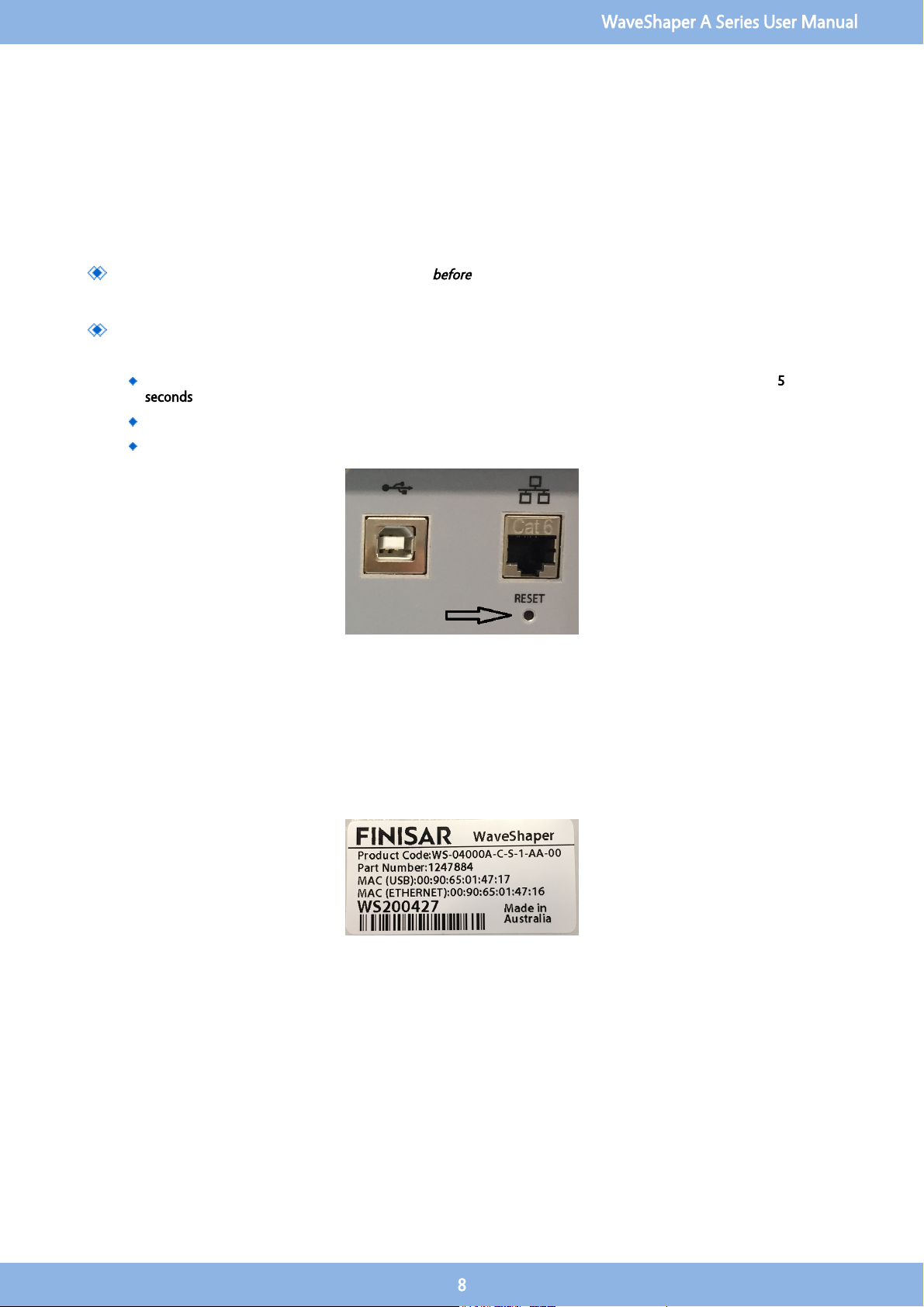
2.4 Can't find the WaveShaper?
If the WaveShaper connected to the network does not appear in the WaveShaper Connect window, then try these steps:
Ensure that the WaveShaper is connected to the LAN
before
powering-on the instrument. The network will only assign
an IP address to the WaveShaper if it is connected to the network before powering on. The default WaveShaper IP
address may cause some issues in some network configurations.
If the WaveShaper still does not appear, it could be due to changes made to the WaveShaper IP settings. The
WaveShaper IP setting can be reset to the default mode with the reset switch. The default mode is
"DHCP then Fixed
IP"
.
While the WaveShaper is running, press and hold the reset switch at the back of the instrument for at least 5
seconds.
Let go of the reset switch and afterwards power cycle the WaveShaper.
The WaveShaper should then be discoverable in the WaveShaper Connect window.
For further detailed technical help, please visit the Finisar KnowledgeBase website.
If there are still connection issues, then please contact us by email: waveshaper@finisar.com
2.5 WaveShaper Mac Address
For both the Module and Benchtop, the MAC addresses of the USB and Ethernet interfaces are printed on the Serial Number
Label.
WaveShaper A Series User Manual
8
Section 3 Graphical User Interface
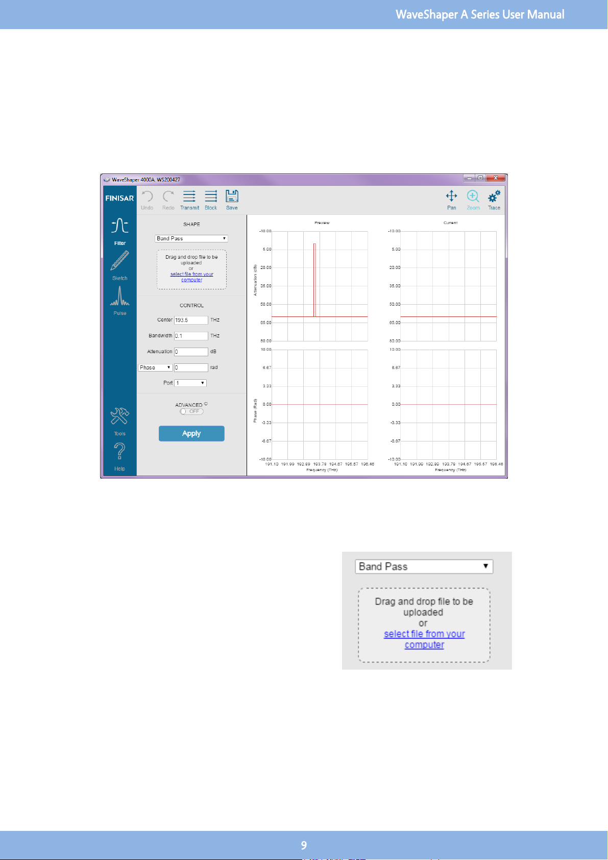
3.1 Filter
3.2 Shape
Optical Filter Profile
For all Series A WaveShapers except the 100A, a preset optical
filter profile can be applied which is defined either by simple
internal profiles stored within the WaveShaper (Flat-top Band-
pass, Gaussian Band-pass or Band-stop) or from a user-
specified filter stored on the users’ computer. (For a
WaveShaper 100A, only the internally-defined Flat-top and
Gaussian Band-pass filter shapes are available).
WaveShaper A Series User Manual
9
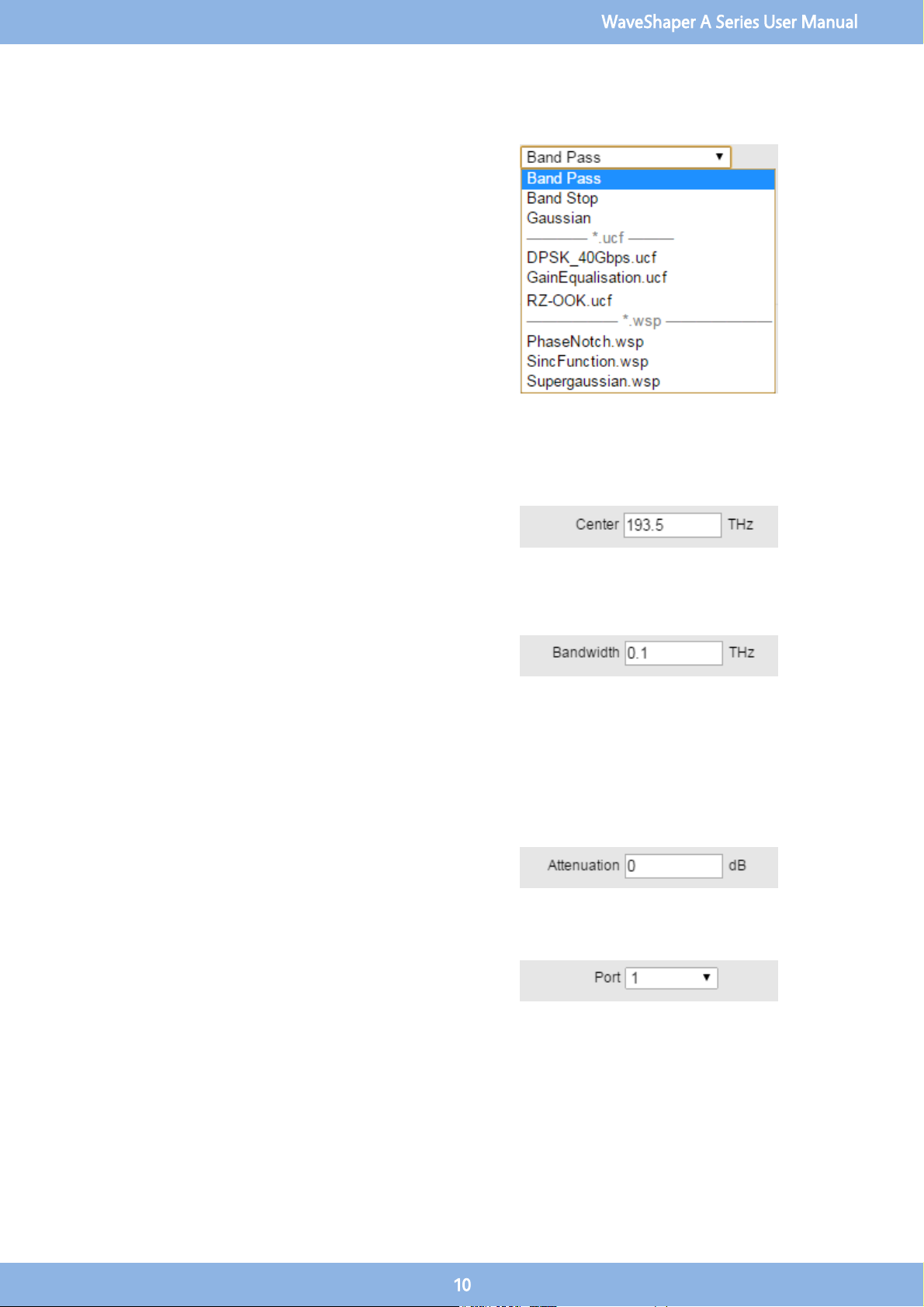
Changing the Optical Filter Profile
When controlling a WaveShaper, the user can select the filter
shape from a drop-down list comprising all pre-programmed
filters (Bandpass, Gaussian, Bandstop), together with User
Configured Filter (UCF) and WaveShaper Preset (WSP) files
stored on the user’s computer. To upload a new *.UCF or
*.WSP file to the WaveShaper, either select it from the drop-
down list or drag and drop it to the indicated area on the
control panel. In all cases, it is necessary to click "Apply" to
upload the new profile.
3.3 Control
Center
This allows the user to set the center frequency of the filter and
is programmable in 1 GHz steps. The value which can be
entered is limited to the operating range of the unit. Center
Frequency control is not available if a WSP file is selected.
Bandwidth
This allows the user to change the bandwidth of the filter
selected in 1 GHz increments. The display shows the nominal 3
dB bandwidth selected. The change in the bandwidth is
symmetric to within ±2 GHz around the center of the filter.
Note: The bandwidth control is accurate for values down to
approximately 20 GHz, below this value the bandwidth
approaches the instrument’s optical transfer function of
approximately 10-12 GHz. Bandwidth Control is not available if
a *.WSP or *.UCF file is selected.
Attenuation
The Attenuation Control provides a power control function for
the current filter. Attenuation control is not available for the
100A or if a WSP file is selected.
Port
The Port Selector Control is only available for the 4000A and
16000A range of Series A WaveShapers. Port Control is not
available if a WSP file is selected.
WaveShaper A Series User Manual
10

4000A
The port selector allows the user to select the port to which the
output is directed. The default value after start-up is Port 1.
16000A
The 4x16 configuration is the default configuration loaded up
when the WaveShaper App is first started. The default values
after start-up are Input Port A and Output Port 1.To select any
of the other available configurations, use the WaveShaper
Configuration option in the Tools tab.
Phase Control
The drop down list box lets the user select how to define one of
phase, group delay or dispersion control values for the
WaveShaper.Phase control is not available for the WaveShaper
100A or WaveShaper 500A or if a *.wsp file is selected.
Phase
Allowable range: -2π to 2π rad
Delay
Allowable range: -25 to 25 ps
Dispersion
Allowable range: -100 to 100 ps/nm (for a 50 GHz bandpass
filter)
3.4 Graph Control
PAN
Allows you to grab the trace and move it to a different part of the graph. The
axes numbers will update automatically. To RESET, use the ZOOM icon and
zoom out.
WaveShaper A Series User Manual
11

ZOOM
Allows you to zoom in on an area of interest. To Zoom IN, drag with the mouse
from top left to bottom right. To Zoom OUT or RESET the graph, drag the
mouse from bottom right to top left on the graph. The axes numbers will
update automatically.
TRACE
Allows you to select and deselect port traces as well as define which graphs are
visible in the WaveShaper App window.
3.5 Advanced
Spectral Range Control
This control allows the user to control the spectral range and, if
required, the repeat function, over which a filter function is
applied. The Window function is used to limit the applied
range of a UCF and also to define the region of the frequency
spectrum which is updated when the "Apply" button is
pressed. The control allows the user to set the 6 dB window
applied to the selected filter in 1 GHz increments from 10 GHz
up to the operating range of the unit. The change in the
window is symmetric around the center of the filter.
Adjustment of the Window is through direct editing in the
entry box. Note: The Window control is accurate for values
down to approximately 20 GHz. Below this value the
bandwidth approaches the instrument transfer function of
approximately 10 GHz.
Repeat Function
The repeat function allows the user to specify repeat
applications of this filter at a specified frequency gap for
a specified number of times (up to the operational limit
of the unit). The Window function is defined at 6 dB as
this is the value which is required to ensure that the
function can be stacked one-against-the-other for use
when switching signals using the WaveShaper 4000A or
16000A to emulate a Wavelength Selective Switch. For a
mathematical derivation of this, see the White paper
entitled "Filter Bandwidth Definition of the WaveShaper
S-series Programmable Processor" available on the Finisar
website.
WaveShaper A Series User Manual
12
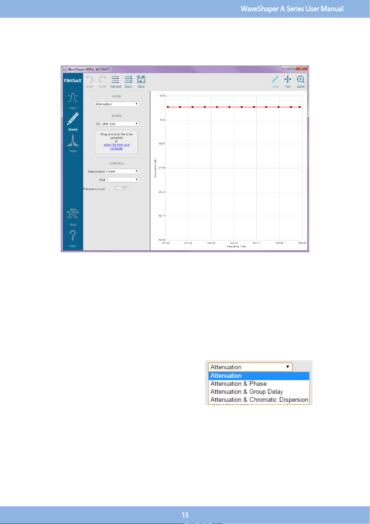
3.6 Sketch
For all Series A WaveShapers except the 100A, the Sketch application provides a powerful and intuitive graphical user interface for
controlling the attenuation, phase, group delay or dispersion of a WaveShaper in real time. With a double-click of a mouse, users
can create data points in the WaveShaper frequency spectrum and, based on the selection of the interpolation method between
the data points, Sketch creates a visual representation of the profile which is loaded into the attached WaveShaper device in real
time.
Sketch provides graphical tools to create, drag and drop, single data points and area selected sets of data points. It has selected
area zoom in and full view reset capability for the graphical view. The created filters can be saved as Preset Point Data files for
future use and exported as WaveShaper Preset (
*.wsp
) files for later downloading direct to supported WaveShapers.
3.7 Mode
Mode Selection
Select what is to be controlled from a drop-down menu. For
the 500A, only the attenuation option is available. When the
Phase, Group Delay and Chromatic Dispersion are selected, a
second graph will appear below the attenuation sketch graph.
A grid can be applied to the second graph for ease of
selection.
WaveShaper A Series User Manual
13
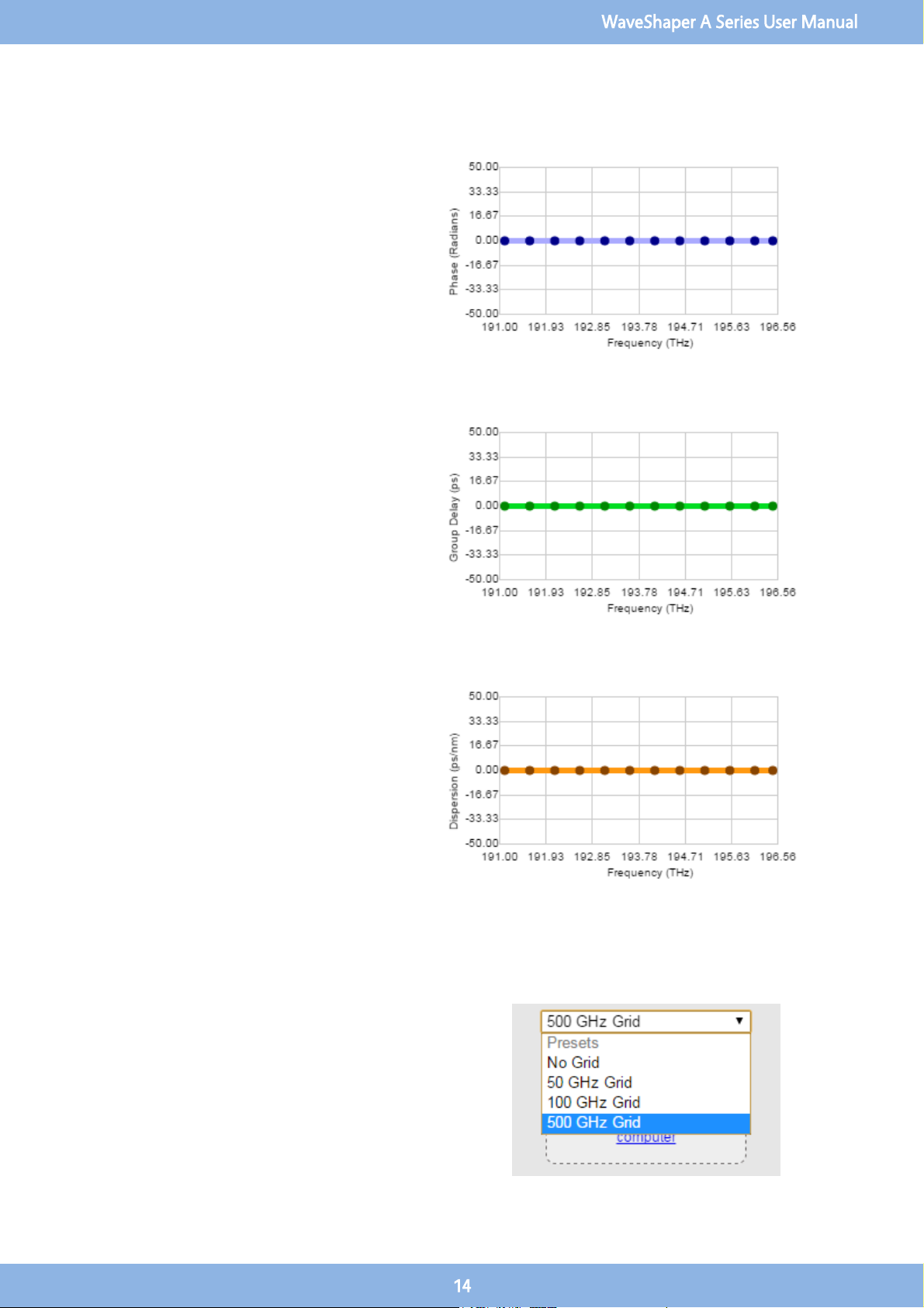
Attenuation and Phase
Allows the adjustment of the phase in the bottom
window. The phase sketch points are blue. The
allowable range is -2π to 2π radians.
Attenuation and Group Delay
Allows the adjustment of the Group Delay in the
bottom window. The phase sketch points are green.
The allowable range is -25 to 25 picoseconds.
Attenuation and Chromatic Dispersion
Allows the adjustment of the Chromatic Dispersion
in the bottom window. The phase sketch points are
orange. The allowable range is -100 to 100 ps/nm
(for a 50 GHz bandpass filter).
3.8 Shape
Grid Selection
Select an existing sketch grid file from the drop-down list or
upload a new file by dragging and dropping it to the
indicated area on the control panel. This allows for easy
selection of predefined points.
WaveShaper A Series User Manual
14

3.9 Control
Interpolation
This allows the user to select the type of interpolation used by
the sketch program to generate the WaveShaper filter profile.
The interpolation takes place between the data point or
points selected and the nearest sketch points on either side.
Nearest Neighbour
Produces a square shaped profile when the points
are adjusted. The points can be adjusted for both
attenuation (vertical direction) or frequency
(horizontal direction).
Linear
Produces a triangular shaped profile when the
points are adjusted. The points can be adjusted for
both attenuation (vertical direction) or frequency
(horizontal direction).
WaveShaper A Series User Manual
15
Cubic Hermite
Produces a rounded profile when the points are
selected. The points can be adjusted for both
attenuation (vertical direction) or frequency
(horizontal direction).
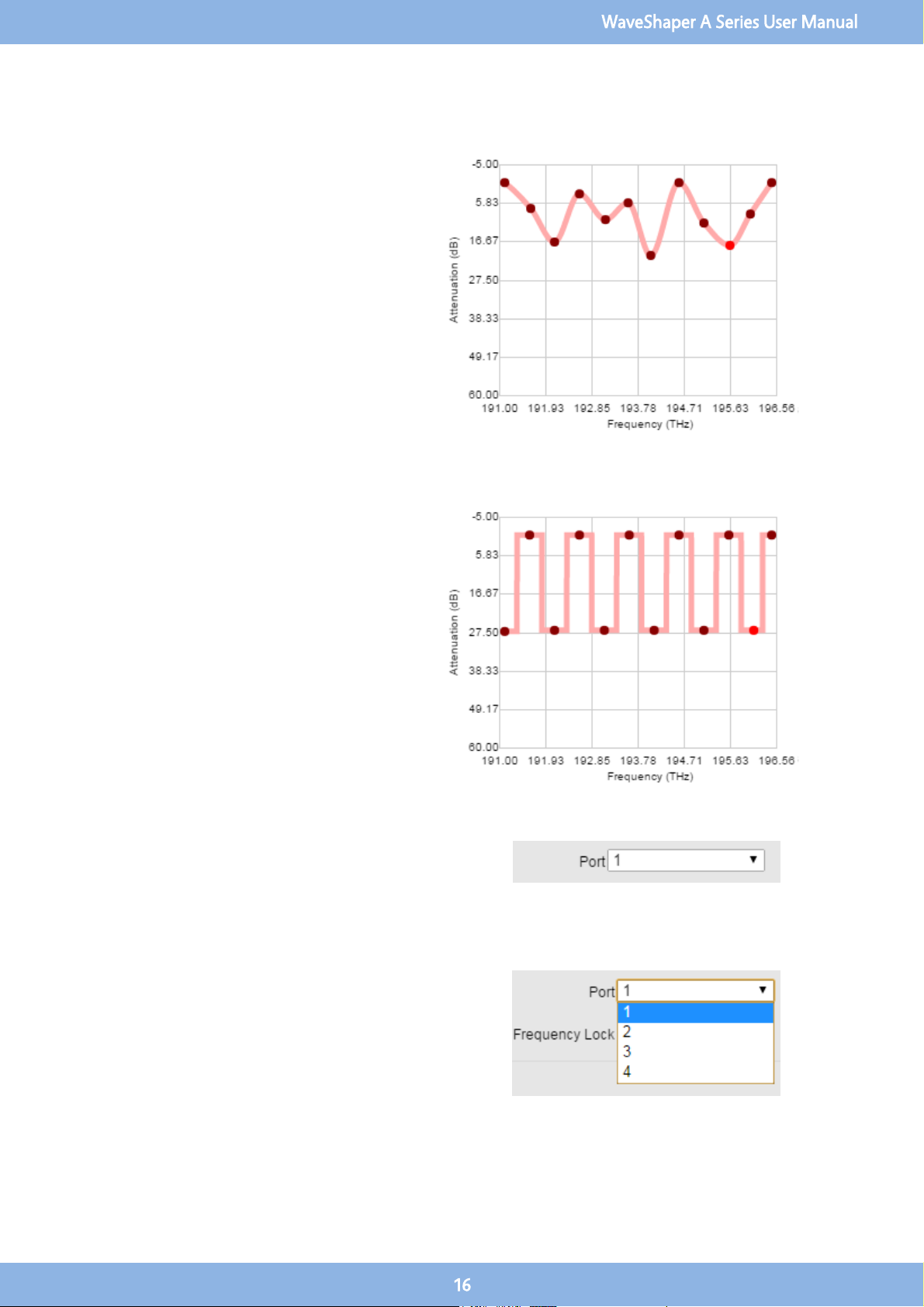
Frequency Lock
When frequency lock is switched on, the frequencies
of any existing points are locked and they can only
be dragged in the vertical (y-) direction (attenuation
adjustment). This allows for the manipulation of the
set channels.
Port
The Port Selector Control is only available for the 4000A and
16000A range of Series A WaveShapers. Port Control is not
available if a WSP file is selected. This allows the user to select
the port to which the output is directed.
Port Selection 4000A
The default value after start-up is Port 1. The user can use the
drop down control to select any of the 4 available output
ports.
WaveShaper A Series User Manual
16

Port Selection 16000A
For the 16000A all ports are indicated by two characters. The
first character is the input port and the second is the output
port. The default configuration file is 4x16 and the default
value for this configuration is A-1. The user can use the drop
down control to select any of the 64 available output ports.
The port selection list will be different for each configuration
and the port list will change depending on the configuration
that is currently active.
4x16 configuration, 64 ports, default A-1
1x19 configuration, 19 ports, default A-B
8x12 configuration, 96 ports, default A-5
10x10 configuration, 100 ports, default A-7
To select any of the other available configurations, use the
WaveShaper Configuration option in the Tools tab.
3.10 Graph Control
DRAW
Allows you to directly manipulate points on the sketch trace. See the section on
Modifying Points for more details.
PAN
Allows you to grab the trace and move it to a different part of the graph. The
axes numbers will update automatically. To RESET, use the ZOOM icon and
zoom out.
ZOOM
Allows you to zoom in on an area of interest. To Zoom IN, drag with the mouse
from top left to bottom right. To Zoom OUT or RESET the graph, drag the
mouse from bottom right to top left on the graph. The axes numbers will
update automatically.
WaveShaper A Series User Manual
17
3.11 Sketch Manipulation
Selecting Points
Click on a single point to select that point. The point
will turn a bright orange colour. By clicking and
dragging that point, you can change the shape of
the sketched profile. Click anywhere else in the
graph area to deselect the point.
Adding Points
Double click on the sketch graph area to add a point
to the sketch profile. This extra data point can be
manipulated by selecting and dragging the point
around in the graph window.
WaveShaper A Series User Manual
18

Grouping Points
Click and drag the mouse to select a group of
points. The selected points turn a bright orange
colour. The group of points can be manipulated by
dragging to a different area in the graph. Clicking
elsewhere in the graph will deselect those points.
Deleting Points
Select a single point or a group of points. Hitting
the delete button will delete the selected point or
points.
Undo and Redo
The Undo and Redo buttons allow you to go back and forward through a
number of changes made to the sketch profile. It will also restore deleted
points from the sketch profile.
WaveShaper A Series User Manual
19
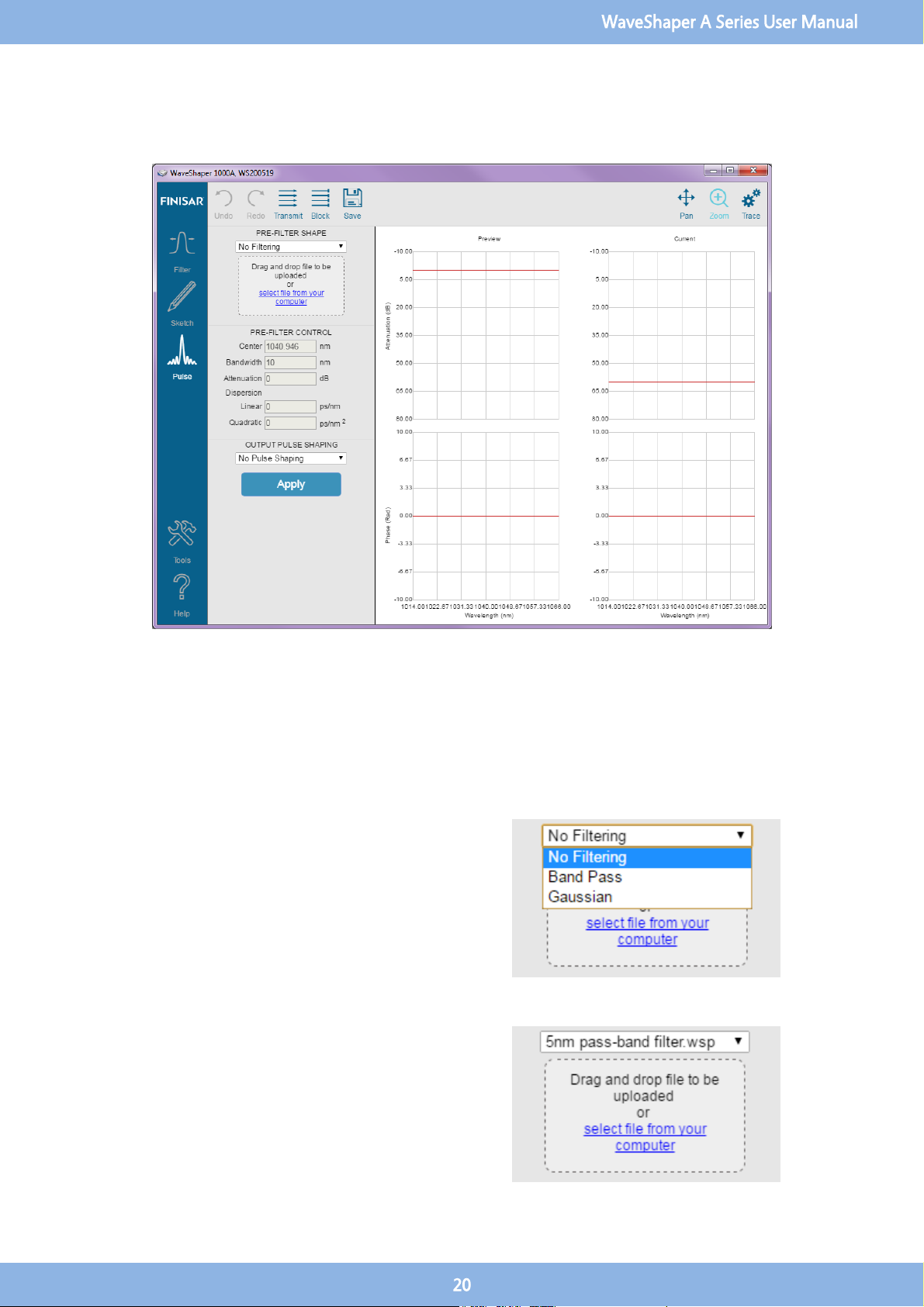
3.12 Pulse Shaping
Pulse shaping is a powerful optical technique whereby the frequency-domain of a pulse or sequence of pulses is manipulated in
order to alter its properties. The dedicated control page in the WaveShaper App allows precise and easy control of the pulse
amplitude and phase to completely define the temporal (or spectral) properties of a laser pulse. The pulse shaping function is
available for all versions of the 1000A, 4000A and 16000A WaveShaper instruments.
3.13 Pre-Filter Shape
Available Filters
Defines a basic filtering scheme. Typically, this pre-filtering is
used to achieve a transform limited pulse shape. The user can
select the filter shape from a drop-down list comprising pre-
programmed Bandpass and Gaussian filters as well as the
option of having "No Filtering".
User Filters
In addition to his this, User Configured Filter (UCF) and
WaveShaper Preset (WSP) files can be uploaded to the
WaveShaper. To upload a new *.UCF or *.WSP file to the
WaveShaper, either select it from the drop-down list or drag
and drop it to the indicated area on the control panel. In all
cases, it is necessary to click "Apply" to upload the new profile.
WaveShaper A Series User Manual
20
Table of contents
Other Finisar Laboratory Equipment manuals

Popular Laboratory Equipment manuals by other brands


Texas Instruments
Texas Instruments MSP-EXP430F5529 user guide

IKA
IKA RCT basic safety control operating instructions

Selecta
Selecta AUTESTER ST DRY PV 18L Clase B instruction manual

Miele
Miele PG 8583 operating instructions

3D Histech
3D Histech PANNORAMIC MIDI RX 1.0 user guide

PerkinElmer
PerkinElmer Lambda 365 Peltier Temp Ctrl Unit Multi installation instructions


