Biotage®PRESSURE+ 48 User Manual | © Biotage 2017
Operation
Warning
• Keep hands, loose clothing, and long hair away from the
manifold when it is moving.
• Only use racks and waste bin inserts supplied by Biotage and
ensure to stack the racks properly on the platform to avoid
spillage. The racks are physically keyed to the platform by three
elevated pins on the platform that recess into the bottom of the
rack. When installed properly, the rack should sit level on the
platform.
• To prevent personal injury and/or equipment damage, always
use impermeable gloves, chemical safety goggles and protective
clothing, follow all generally-accepted lab safety procedures and
applicable laws and regulations, and consult your company’s
safety expert for guidance.
Step-by-Step Instructions
1. Ensure the unit is connected to a gas supply; see Installation
section on page 2.
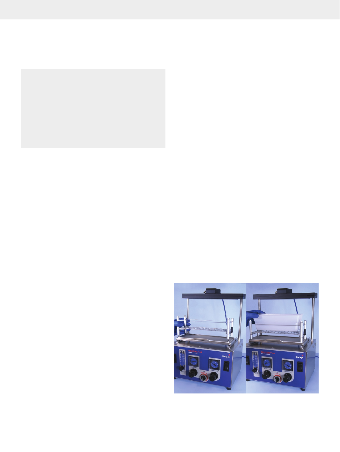
2. Place a waste bin rack and a waste bin insert on the
platform; see Figure A.
3. Insert desired number of columns in a column rack. Each
column will be pressurized equally even if columns are
omitted.
4. Place the column rack on top of the waste bin rack and add
sample; see Figure B.
5. Slide the platform back to position the column rack under
the manifold; see Figure C.
6. Turn on the gas for the rows in use, i.e. toggle the
appropriate gas switch(es) on top of the manifold to the ON
position. There are four switches; one switch for each row of
columns. See Figure D.
7. Turn the flow control switch to the left to the Adjustable Flow
position; see Figure E.
8. Adjust the regulator and rotometer to achieve the desired
flow rate; see Figure F.
IMPORTANT: As indicated on the label, never turn the
rotometer completely off. Seating the needle valve into its
orifice can damage the unit.
9. Lower the manifold by pressing down on the two rocker
switches simultaneously for approximately 3 seconds; see
Figure G.
10. When all liquids have passed through the columns, turn the
flow control switch to the OFF position. See Figure H.
11. Raise the pressure manifold by pressing up on the two
rocker switches simultaneously.
12. Pull out the platform.
13. Add wash solvent to each column and slide the platform
back to position the column rack under the manifold.
14. Lower the manifold by pressing down on the two rocker
switches simultaneously for approximately 3 seconds.
15. Turn the flow control switch to the left to the Adjustable Flow
position; see Figure E.
16. Turn the flow control switch to the right to the Maximum
Flow position and adjust the manifold pressure to the
desired setting for the drying period; see Figure I.
17. When the drying period is completed, turn the flow control
switch to the OFF position. See Figure H.
18. Raise the manifold by pressing up on the two rocker
switches simultaneously.
19. Pull out the platform and replace the waste bin rack with a
collection rack; see Figure J.
20. Add elution solvent to each column.
21. Allow the samples to elute by gravity or repeat step 5
through 12 for pressure assisted elution. Tip: To trigger
gravity elution, slide the platform back to position the
rack under the manifold, ensure the flow control switch is
in the OFF position and then lower the manifold. Raise the
manifold after a few seconds.
IMPORTANT: The unit should always be in the OFF position
during compression and decompression cycles and when not in
use. Always shut off the external gas supply when the unit is not
in use.
Operation
A


