Finwing SABRE 1900 User manual

USER MANUAL
FINWING SABRE 1900FINWING SABRE 1900
FINWING TECHNOLOGY
WWW FINWINGHOBBY COM
PATENT PENDING
..

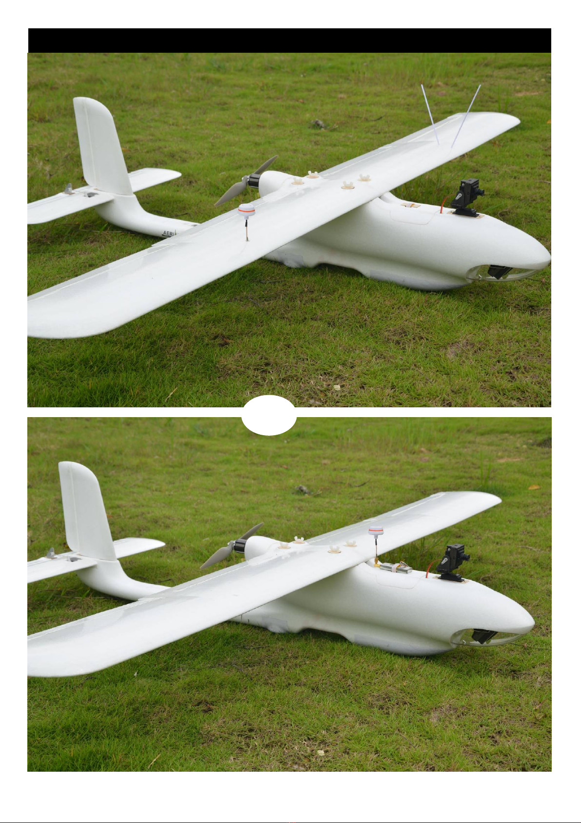
Finwing Sabre
.
This manual aims to help direct the user on how to build the Sabre RC plane.
Please visit the Finwinghobby com official website for more introductions.
Please read through the manual carefully before installation and flying
Warning:
1 This model airplane is not a toy not recommended for children under 14 years old., ,
2. Be cautious and prepared while flying this plane as a range of issues could lead to a crash
including the environment/weather, speed, pilot error, improper building/testing,
interference or other component failures
3. Flying field: Choose an adequate flying space at least 100 meters long/wide and in an unpopulated
and non-built up area for safe flying. This includes avoiding flying over cities or other populated areas.
4. Please don't fly this model airplane in bad weather including rainy and/or windy environments.
5. Remember to unplug your flight/video battery when not in use to avoid any interference to others
who might be on similar channels.
6. Please remember switch on the transmitter first before connecting the battery, and disconnect
the battery first before switching off your transmitter.
7. Keep away from the propeller when the Airplane is powered as it can be dangerous and could
lead to injury. Keep the powered plane away from children at all times to avoid any accidents or injury.
.
The Tail-boom has been split from the fuselage in order to fit into a smaller package
that will also help to save on overall shipping costs.
Finwing Sabre Basic information
Wingspan:1900MM (74.8”)
Length :1320MM (52”)
Propeller :11*5.5" / 11*6"
Flap :Available (Options)
Max.AUW :4.0kg (8.8IB)
EFFICIENT AUW:3.1-3.5kg (6.8-7.7IB)
Hand launching :Available
Belly Armour :Options
Standard Nose cover:Included
Steerable undercarriage:Options
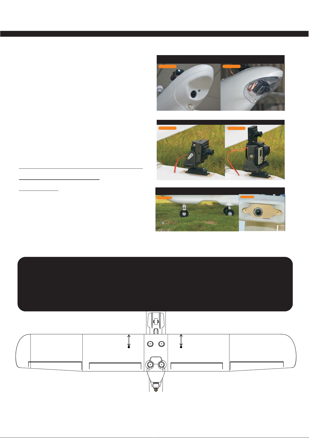
Module1:Hero Nose cover
Module2:Gimbal with transparent cover
Module3:Downward facing filming
Hero 390/300 degree Pan&Tilt system
Mini Camera 390/300 degree Pan&Tilt system
Professional Modules specially designed
ForHDaerialphotography
Options Only
()1PCS Brushless Motor M2820 3542
1PCS Premium Brushless 60A ESC OPTO
1PCS UBEC 6A
3PCS 23g Metal servo
1PCS 9g Plastic servo
()1PCS Brushless Motor M2815 3536
1PCS Brushless 60A ESC SBEC
3PCS 17g Plastic servo
1PCS 9g Plastic servo
390 300 FPV Hero Pan Tilt
00
/&
390 300
00
/&FPV Mini Pan Tilt
FSA01 Module1
Hero Filming Nose Cover
-
OPTIONS ONLY OPTIONS ONLY
FSA02 Module2
Gimbal Filming Nose Clear Cover
-
+
FSA04
Steerable Undercarriage
OPTIONS ONLY
OPTIONS ONLY
Including 1PCS 23g Metal Gear Servo
FSA03
Module3 Downward Filming
Sabre Premium Power system Sabre advanced Power system
OPTIONS ONLY OPTIONS ONLY
OPTIONS ONLY OPTIONS ONLY
CG 82 5 85MM 3 2 3 3 From the leading edge. .- (."-.")
No Dome
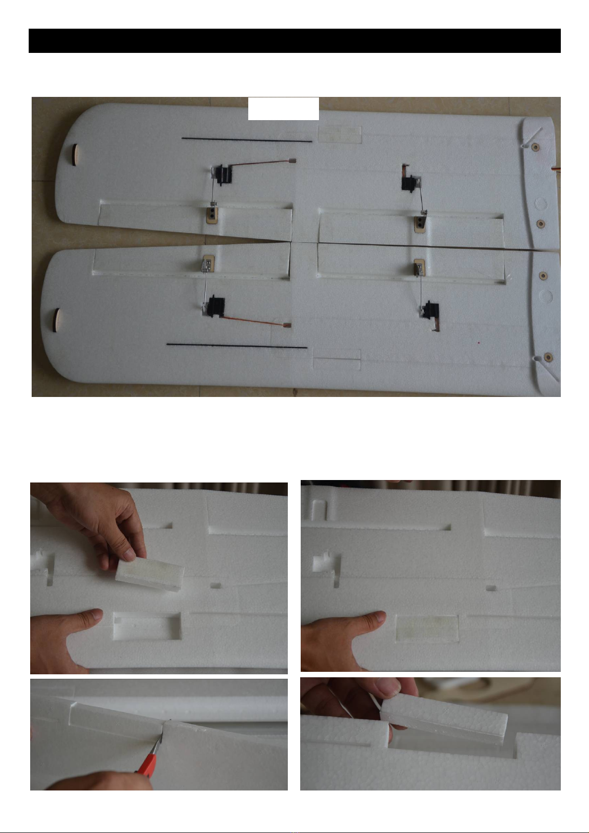
FinwingSabreWingsinstallation
Aileron:17gPlasticGearServoor23gMetalGearServo.Flap:9gservo
Flapisnotmust,Dependsonyourflyingpreference.
1>TherearetwoslotsforVTXandUHFseparatelyonleftandrightwing,thepurposeistoavoidsignal
interferenceespeciallylongrangeflyingsystem.pleasecutouttheslotfoamaccordingtoyou
equipments'sizebeforeclosingthewing‐cover,
Pleaseskipifyouwon'tputVTXandUHFonthemain‐wing.Forexampleputitonthecockpitandtail‐
boomisalsonoproblem.it'sdependsonyourpreference.
Overview

2>Preparetheextensionwiresfirst,kitspackageincludedAileronextensionwiresbutnoextension
wiresforflapservos.Spreadinggluetothemainwingcave,unnecessarygluetothewing‐cover.
Gluingtimeapproximately3‐4minutes,gluewilldryquicklyiftoolong.
Afterclosingwing‐cover,it'stimetoinstallthecarbonstripwithalittleglue,andothersmallpartsas
thephotosshown.
Pressitfirmlyintermittentlybythefirsthalfhour
Installcarbonstripwithalittleglue
Roomtemperaturedryingabout24hoursbeforeflying

3>Cutoffthesideconnectionofthecontrolsurfaceuntilfeelingthecontrolsurfaceisrotatablefreely
Aileron,flapandElevatoralldothesame
Forexamplehowtoreinforcethebottomside,movethecontrolsurfacetothemax.upposition,then
wrappingtapeadheretotheslot,pressitfirmly.Movethecontrolsurfacetothemax.downposition
whenreinforcethetopsideaccordingly
CutofftheSideconnectionofcontrolsurface
Reinforcethehingeisnecessaryforbothsidesjustbythewrappingtape

Tips:Laminatethewing
wrappingtapetolaminateismoreefficientandeasywaytoprotectyourairplane,butthisisnotthe
mustworks.Pleaseskipifyoudon'twanttolaminate
Beforelaminating
laminated

4>Neutralizeallservos,preparetoinstallAileron,Flapservos,
Note*fla
p
travelisnotthebi
gg
erthebetter,A
pp
roximatel
y
10MMisoka
y
Aileron
Aileron
Flap
Flap
Aileron Aileron
Flap Flap
10MM
Flaptravel≈10MM
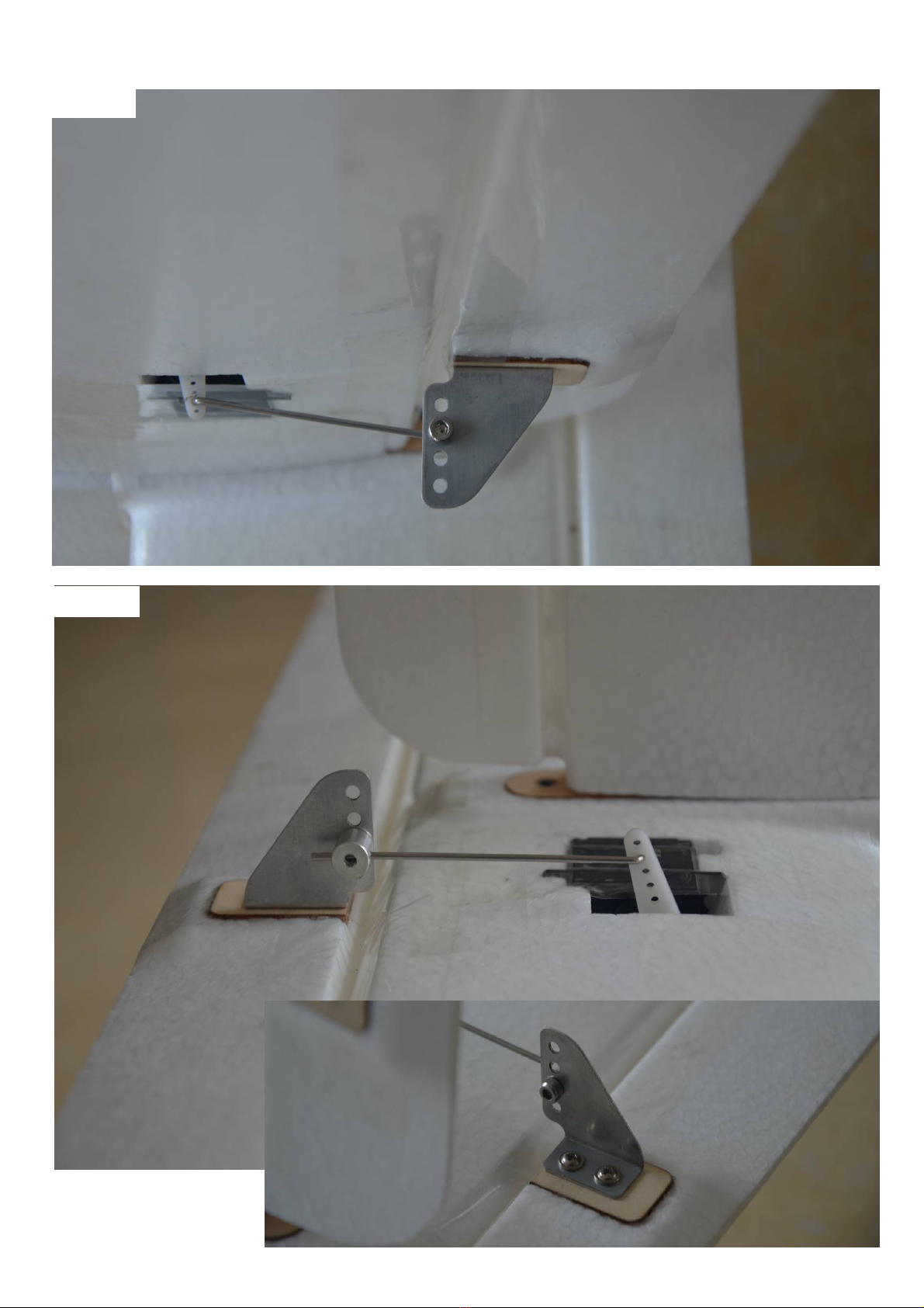
5>ElevatorandRudderinstallationissimilartoAileron.
Elevator
Rudder
Finwin
g
SabreFusela
g
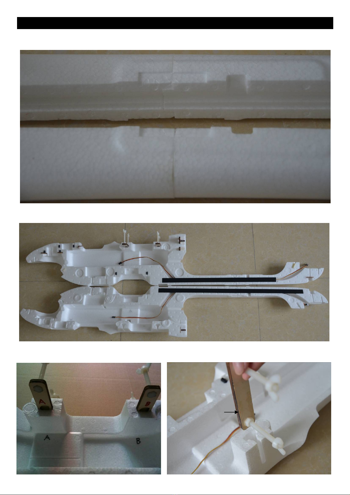
einstallation
1>Jointail‐boomtofuselage,gluetothejointcontactsurfacethenpressingfirmly
Don'tmoveitatleasttwohoursdryingtimeatroomtemperature,besuredon'ttwistthetail‐boom!
2>Twohourslater,installthetailcarbonstrips,don'tforgetextensionwiresfirst,andsomeother
extensionwiresif
y
ouneed.Forexam
p
leUHForGPSextensionwires
3>installthewing‐fuselagejointparts,alittleglueisnecessary,AandBjointpartsatcorrectslot
Glue
Roomtemperaturedryingaboutoneortwohours
Roomtemperaturedryingaboutoneortwohours

4>installtheplywood,themotormountwillbesecuredtothisplywoodbyscrews
5>Doublecheckingthefuselageagain,besurenopartsmissing!
Glue
Glue

6>It'stimetoclosethefuselage,recommendgluetotherighthalffuselage,unnecessarygluetoboth
halffuselage,oralittlegluetothelefthalfoffuselageisokaybysomeofthecontactsurface.Costabout
8‐9minutesspreadinggluetotherighthalfoffuselage,gluewilldryquicklyiflasttoolong!
Pressingfirmlybyallpartofthefuselageintermittently,especiallyduringthefirsthour.
Roomtemperaturedryingabout24hoursbeforeinstallationofmotor
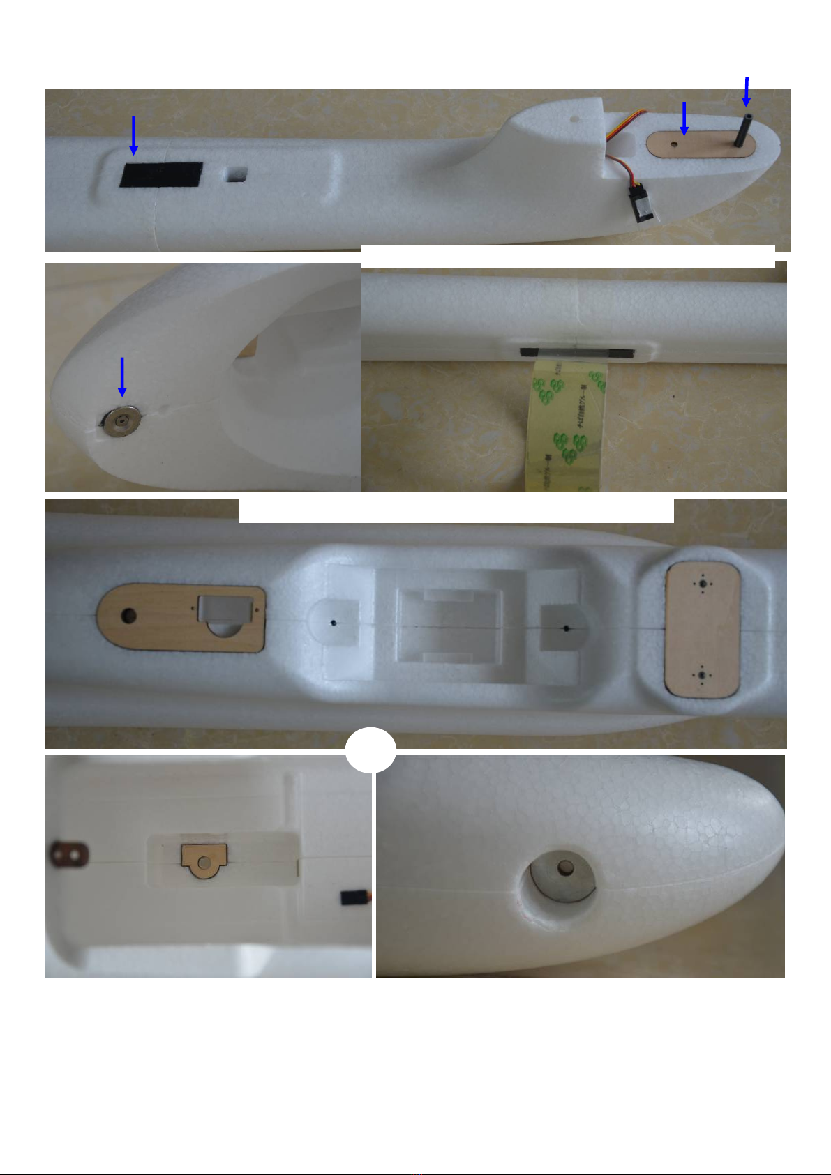
7>Installthefollowingpartswithglueduringtheperiodoffuselagedrying
Rememberletthefuselagedryabout24hoursatroomtemperature,atthisperiodyou
caninstallWings,Module2,Undercarriageetc…
Magnet
CarbonStrip
Recommendwrappingtapearoundthetail‐boomjoint
Pleaseskipthisifnoundercarriage,handlaunchingonly
Frontgearlocker Screwwasher

8>ESCandMotorinstallation
ESCsecuredtothesideoffuselage,it'sverygoodforcooling,
BacktobackVelcroincluded,cuthalfoftheVelcro,oneforESCandanotherforVTX
Securethemotortothemotormountplywoodbywashersandscrewsfromkits'package(included)
withouttraditionalcrossshapemotormountisgoodtoreducethesizeofairplane'smotormountand
produceaslessairdragaspossible
Securethemotormountplywoodtotheairplanebywashersand3PCSlongscrews(3*35MM)
MostofthePropellershouldbe:embedwordstowardthenoseofairplane,don'tbewrongdirection!
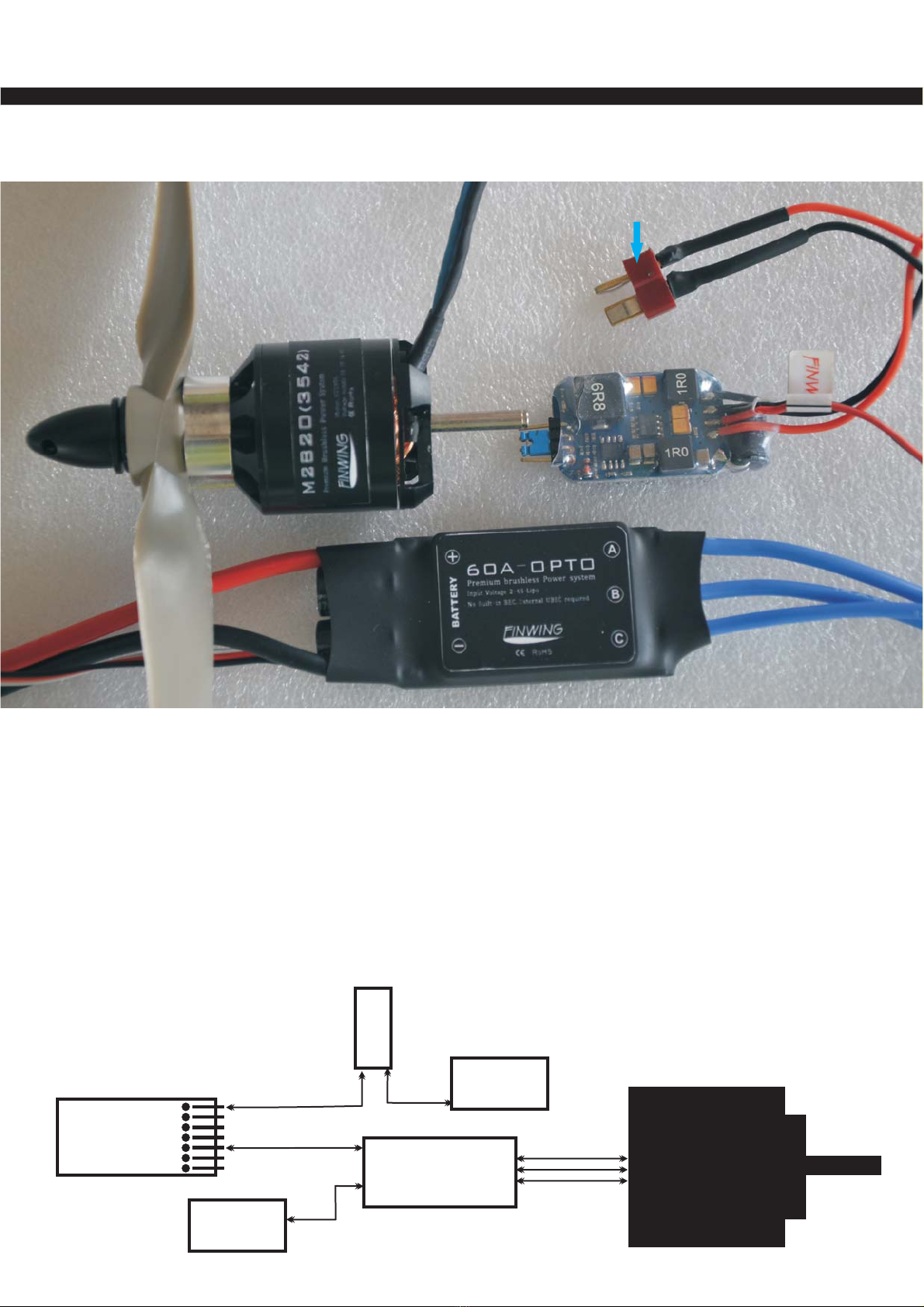
Finwing Sabre Power System
The following photo shown is sabre premium power system
Please solder a connector for the BEC power input
Connector type is depends on what type of your battery s connector'
6CH Receiver
()For Example
1
2
3
4
5
6
B
ESC A
Opto
60
34-SLipo
Battery
FINWING
()
M2820 3542
ESC A
Opto
60
BEC
26-SLipo
Battery
The premium A ESC opto plus a external BEC 6A
This combo is more safety and efficient to supply your airplane espeically
FPV flying need supply lots of FPV gears undercarriage Pan Tilt etc
Diagram of wires connection Premium power system
ESC type Opto without buit in BEC
External 6A BEC
, , & , ...
()
*: -
*
60
BEC Specification
()Output: 5V/6A,5.5V/6A,6V/6A Switchable by the Blue jumper
Input: 5V-25V (2-6S Lipo, 5-18S NiMH/Nicd)
Continuous Current 6A, Brust current 10A
UBEC should be at least 5CM away from the receiver to avoid electronic interference
6CH Receiver
()For Example
1
2
3
4
5
6
B
ESC 60A
(-)with built in BEC
34-SLipo
Battery
FINWING
()
M2815 3536
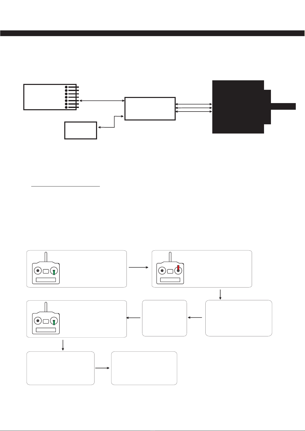
,, .
Throttle calibration setting is required by all power system for The first time use
or changed new transmitter replaced ESC motor and battery
*: " "Note it may cause lost throttle signal if no throttle calibration
Throttle stick to
the Maximum Position
Power on BEC
Power on ESC
waiting for a moment
Seconds<>2
You can hear
the motor
Beep or Beep Beep-
Move throttle stick to
the Minimum Position
immediately
Motor Beep
Indicating cell number
and signal confirmation
Throttle calibration done
.....
Ready to fly now
Finwing Sabre Power System
Diagram of wires connection Advanced power system
ESC type with build in UBEC SBEC
()
*: -/
Switch on Transmitter
for two second
Note USA EU flyers transmitter the throttle stick should be at the left side of transmitter:, ' ,
Throttle calibration

Undercarria
g
e
1>assemblythefrontgearasthephotosshown
2>installundercarriagenow,installthereargearfirst,thenneutralizethe(23g)metalgearservo
installthefrontgearasphotosshown.Adjusttheundercarriagedirectioncorrectlybeforeflying
Servowireoutlet
EClasp
RearGear

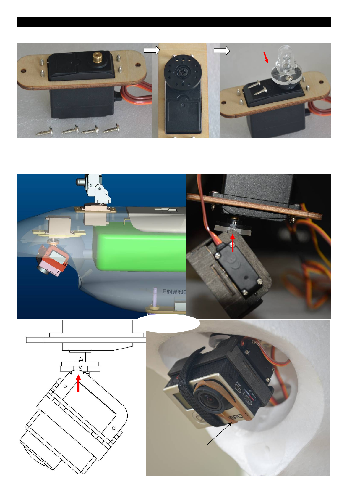
Module2
>Secureplywoodtotheservo,thenSecuretheservoarmandthejointarmsubsequently,Gearofthe
j
ointarmtowardtheri
g
htsideas
p
hotosshown
>InstalltheTiltmodule,recommendinitialpositionasthephotosshown,butyoucanadjustit
accordingtoyourreference,youcaninstallitmoredownwardifyouwouldlikedownwardvideomost
ofthetime.FYI:Wealsoflyingwithoutrubberbandandvideonovibration,
Gear
AntivibrationRubberband
FYIFPVGearsLayout
OR
UHF
UHF
VTX
VTX
Table of contents
Popular Tools manuals by other brands


Chicago Electric
Chicago Electric 92196 operating instructions

Ryobi
Ryobi A18MS01 Manuel d'utilisation

Hyundai power products
Hyundai power products HCOMBI336F-A Original instructions

HOZAN
HOZAN L-804 instruction manual

DeWalt
DeWalt DCS438 instruction manual

BIAX
BIAX BE 309 R Translation of the original operating manual

Reelworks
Reelworks 27807153 instruction manual

GREINER
GREINER PneumoLash LCV Operating instructions and spare parts list

Lukas
Lukas LZR Series operating instructions

Neilsen
Neilsen CT4448 Original instruction

Hytorc
Hytorc Torque Gun Digital jGun DJ-.25 Operation manual

Performance Tool
Performance Tool W54290 user manual