FIOR & GENTZ NEURO FLEX MAX Operation instructions

09-12-18 1/55 Joint Assembly NEURO FLEX MAX
09-12-18 1/55 Joint Assembly NEURO FLEX MAX
Joint Assembly NEURO FLEX MAX
This online tutorial describes the joint assembly for locked system knee joints using the
example of the NEURO FLEX MAX in its basic function. The basic function includes a lock lever
and a locating pin that are used to activate the permanent unlock function. Due to the
constructional differences, the NEURO FLEX MAX system knee joint is assembled a little
differently than the NEURO LOCK and the NEURO LOCK MAX.
For example, the NEURO LOCK has, in contrast to the NEURO LOCK MAX and the NEURO FLEX
MAX, no permanent unlock function. Furthermore, a flexion stop disc is already integrated into
the joint's lower part of the NEURO LOCK MAX system knee joint, whereas, in the case of the
NEURO FLEX MAX, it still needs to be mounted.
Consult the manual (chapter 11 “Assembly Instructions”) of the corresponding system joint to
learn about the differences regarding
mounting the extension stop,
mounting the spring unit and the locking pawl,
mounting the cover plate and
checking the lock function.
Besides, this online tutorial shows in detail the four alternative functions of the NEURO FLEX
MAX system knee joint.
Note: You will find information regarding torque (Nm) and locking pawls for all system widths in
the manual of the corresponding system joint.

09-12-18 2/55 Joint Assembly NEURO FLEX MAX
09-12-18 2/55 Joint Assembly NEURO FLEX MAX
Basic Function
Step 1/23
Clean the system joint.
Step 2/23
If you are using a supporting joint, shorten the extension stop damper with a
sharp knife. Now, the system joints reach the extension stop at the same
time and the locking pawl should lock without difficulty.
Step 3/23

09-12-18 3/55 Joint Assembly NEURO FLEX MAX
09-12-18 3/55 Joint Assembly NEURO FLEX MAX
Apply spray adhesive to one side of the first sliding washer and adhere it to
the cover plate. Grease the other side of the sliding washer slightly with the
delivered orthosis joint grease.
Step 4/23
Place the flexion stop disc on the joint's lower part and press both by using a
vice.
Note: Use a vice with plain or soft jaws in order not to affect the joint
function.
Step 5/23

09-12-18 4/55 Joint Assembly NEURO FLEX MAX
09-12-18 4/55 Joint Assembly NEURO FLEX MAX
Mount the extension stop to the joint's upper part.
Step 6/23
If you have to demount the extension stop, screw it out of the joint's upper
part by using the pan head screw delivered with the system joint. If it is
mounted correctly, you do not have to demount the extension stop.
Step 7/23
Insert the pressure spring by pushing it from below into the spring duct of

09-12-18 5/55 Joint Assembly NEURO FLEX MAX
09-12-18 5/55 Joint Assembly NEURO FLEX MAX
the joint's upper part.
Step 8/23
Grease the axle bore of the locking pawl and the friction surfaces of the
bearing nut with the delivered orthosis joint grease.
Step 9/23
Put the bearing nut into the intended opening of the joint's upper part and
make sure that it is in the correct position. Fix the bearing nut with one
finger. Mount the locking pawl.
Step 10/23

09-12-18 6/55 Joint Assembly NEURO FLEX MAX
09-12-18 6/55 Joint Assembly NEURO FLEX MAX
Place the ball and push the locking pawl to the top. Insert the pressure
spring and the locating pin for adjusting the permanent unlock function in
the locking pawl.
Step 11/23
Push the locating pin against the spring force into the system joint until it
locks in the joint's upper part. The locking pawl is now secured, which
facilitates the following assembly of the system joint.
Step 12/23

09-12-18 7/55 Joint Assembly NEURO FLEX MAX
09-12-18 7/55 Joint Assembly NEURO FLEX MAX
Grease the axle bore of the joint axis and the friction surfaces of the bearing
nut with the delivered orthosis joint grease.
Step 13/23
Put the joint axis’ bearing nut into the intended opening of the joint's upper
part and make sure that it is in the correct position. Fix the bearing nut with
one finger.
Step 14/23
Grease the second sliding washer slightly with the delivered orthosis joint
grease.
Step 15/23

09-12-18 8/55 Joint Assembly NEURO FLEX MAX
09-12-18 8/55 Joint Assembly NEURO FLEX MAX
While still fixing the bearing nut, place the second sliding washer onto the
joint's upper part and mount the joint's lower part.
Step 16/23
Mount the cover plate. Turn in the first countersunk flat head screw (axle
screw). Continue with the second countersunk flat head screw while still
fixing the bearing nut.
Step 17/23

09-12-18 9/55 Joint Assembly NEURO FLEX MAX
09-12-18 9/55 Joint Assembly NEURO FLEX MAX
If the sliding washer has been damaged during the assembly of the cover
plate (audible cracking), remove the particles and place a new sliding
washer.
Step 18/23
Check if the bearing nuts are placed completely in the intended openings.
Note: The delivered screws are always matching the system joint. Even if the
screws are not as long as the thread of the bearing nuts, that does not affect
the system joint’s load capacity.
Step 19/23
Check if the system joint moves freely. Bring the system joint in extension.
In order to check the flexion, hold the orthosis in a horizontal position and
then let go of the femoral shell. The femoral shell should smoothly fall
downward until it has reached the maximum possible flexion grade. If the

09-12-18 10/55 Joint Assembly NEURO FLEX MAX
09-12-18 10/55 Joint Assembly NEURO FLEX MAX
system joint does not move freely, mount the next thinner sliding washers,
repeat all steps from step 12 onwards and check again.
Note: With a bilateral orthosis, only check one system joint at a time.
Step 20/23
Check if the system joint moves without lateral play. Hold the tibial shell and
try to move the femoral shell in varus-valgus direction. If the system joint
runs with lateral play, mount the next thicker sliding washers, repeat all
steps from step 12 onwards and check again.
Note: At a bilateral orthosis, only check one system joint at a time.
Step 21/23
Bring the system joint as far as possible in extension. Then, disable the
permanent unlock function by pressing the locking pawl against the joint's
upper part. Check if the locking pawl is locked. Fix the tibial shell and try to
move the femoral shell against it. There should be no movement in the

09-12-18 11/55 Joint Assembly NEURO FLEX MAX
09-12-18 11/55 Joint Assembly NEURO FLEX MAX
Alternative Function 1
system joint.
Note: Mind the information on the locking pawls in the manual.
Step 22/23
Check the position of the locking pawl. You can see the correct position on
the left picture. If the locking pawl does not fit well, exchange it.
Step 23/23
Secure both screws with LOCTITE 243 medium strength and the torque
corresponding to the system width.

09-12-18 12/55 Joint Assembly NEURO FLEX MAX
09-12-18 12/55 Joint Assembly NEURO FLEX MAX
Step 1/28
The locked system joint can be used for locking in different flexed positions
(alternative function 1) by exchanging the locking parts. To do so, exchange
the extension stop according to the intended extension position by choosing
a degree.
Note: You will find the article numbers of the extension stops in our product
catalogue System Joints and Articulated System Side Bars.
Step 2/28
Secure the locking pawl (permanent unlock function). Disassemble the
system joint.
Step 3/28

09-12-18 13/55 Joint Assembly NEURO FLEX MAX
09-12-18 13/55 Joint Assembly NEURO FLEX MAX
Demount the flexion stop disc. To do so, clamp the flexion stop disc in a vice
and carefully lever it of the joint's upper part.
Note: Use a vice with plain or soft jaws in order not to affect the joint
function.
Step 4/28
Demount the extension stop. To do so, screw it out of the joint's upper part
by using the pan head screw delivered with the system joint.
Step 5/28
09-12-18 14/55 Joint Assembly NEURO FLEX MAX
09-12-18 14/55 Joint Assembly NEURO FLEX MAX
Demount all further system components. Clean the system joint. Check all
system components and exchange them if there are signs of wear.
Note: Follow the maintenance instructions in the manual of the system joint.
Step 6/28
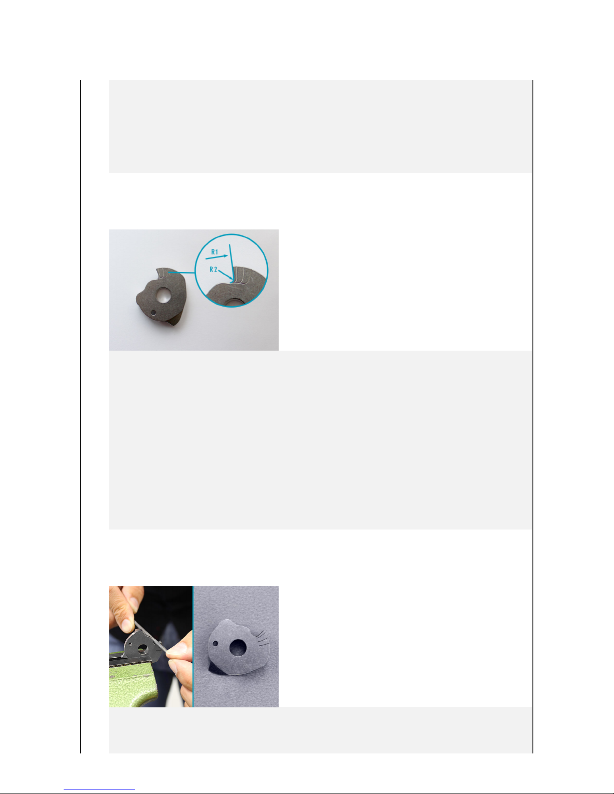
The flexion stop disc is marked with lines that serve as a guide when filing
the desired flexion and thus enable an accurate locking of the pawl at the
lock area (R1). The marked lines are not straight but slightly bent! Do not
use a flat file and ensure a smooth transition from lock area to lock disc
(R2).
Note: Mount the system joint in order to check the proper locking function
and to be able to readjust the flexion degree, if required.
Step 7/28
File the flexion stop disc according to the flexion grade corresponding to the

09-12-18 15/55 Joint Assembly NEURO FLEX MAX
09-12-18 15/55 Joint Assembly NEURO FLEX MAX
extension stop. The line should remain visible! Make sure that the stop face
remains even and is not inclined to the sides.
Step 8/28
Place the flexion stop disc on the joint's lower part and press both by using a
vice.
Note: Use a vice with plain or soft jaws in order not to affect the joint
function.
Step 9/28
Apply spray adhesive to one side of the first sliding washer and adhere it to
the cover plate. Grease the other side of the sliding washer slightly with the
delivered orthosis joint grease.
Step 10/28

09-12-18 16/55 Joint Assembly NEURO FLEX MAX
09-12-18 16/55 Joint Assembly NEURO FLEX MAX
Mount the extension stop to the joint's upper part.
Step 11/28
Insert the pressure spring by pushing it from below into the spring duct of
the joint's upper part.
Step 12/28
If you exchange the delivered locking pawl with another, choose the
smallest possible locking pawl that still fits. As locking pawls are wear parts

09-12-18 17/55 Joint Assembly NEURO FLEX MAX
09-12-18 17/55 Joint Assembly NEURO FLEX MAX
and wear out, you can then mount the next bigger locking pawl, if
necessary.
Note: Mind the information on the locking pawls in the manual.
Step 13/28
Grease the axle bore of the locking pawl and the friction surfaces of the
bearing nut with the delivered orthosis joint grease.
Step 14/28
Put the bearing nut into the intended opening of the joint's upper part and
make sure that it is in the correct position. Fix the bearing nut with one
finger. Mount the locking pawl.
Step 15/28

09-12-18 18/55 Joint Assembly NEURO FLEX MAX
09-12-18 18/55 Joint Assembly NEURO FLEX MAX
Place the ball and push the locking pawl to the top. Insert the pressure
spring and the locating pin for adjusting the permanent unlock function in
the locking pawl.
Step 16/28
Push the locating pin against the spring force into the system joint until it
snaps in the joint's upper part. The locking pawl is now secured, which
facilitates the further assembly of the system joint.
Step 17/28

09-12-18 19/55 Joint Assembly NEURO FLEX MAX
09-12-18 19/55 Joint Assembly NEURO FLEX MAX
Grease the axle bore of the joint axis and the friction surfaces of the bearing
nut with the delivered orthosis joint grease.
Step 18/28
Put the joint axis’ bearing nut into the intended opening of the joint's upper
part and make sure that it is in the correct position. Fix the bearing nut with
one finger.
Step 19/28
Grease the second sliding washer slightly with the delivered orthosis joint
grease.
Step 20/28

09-12-18 20/55 Joint Assembly NEURO FLEX MAX
09-12-18 20/55 Joint Assembly NEURO FLEX MAX
While still fixing the bearing nut, place the second sliding washer onto the
joint's upper part and mount the joint's lower part.
Step 21/28
Mount the cover plate. Turn in the first countersunk flat head screw (axle
screw). Continue with the second countersunk flat head screw while still
fixing the bearing nut.
Step 22/28
Other FIOR & GENTZ Mobility Aid manuals

Popular Mobility Aid manuals by other brands

Timago
Timago TGR-R RS 881 Instructions for use

Drive
Drive euro style manual

Freedom Innovations
Freedom Innovations Plie 3 owner's guide

Invacare
Invacare Ulti-Mate Air Back Installation and operating instructions

AMF-BRUNS
AMF-BRUNS FUTURESAFE operating instructions

NRS Healthcare
NRS Healthcare M11090 User instructions

Thomashilfen
Thomashilfen 6813 Assembly instructions

Dolomite
Dolomite FUTURA user manual

Invacare
Invacare WALKING TUTOR WT 200 Installation and operating instructions

Invacare
Invacare Banjo P452E/3 operating instructions

hugo
hugo 700-957 quick start guide

Easylife
Easylife 2419 / HL-S0001 instruction manual


