Eurofyre CRISIS Operation manual
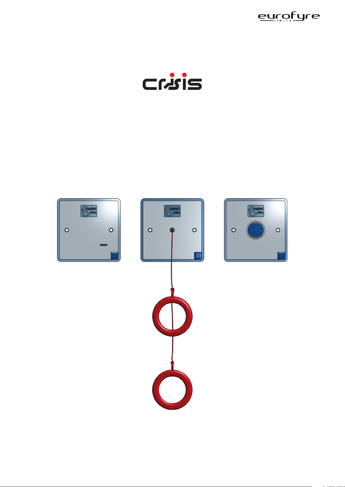
Assist Call WC Kit
Installation & User Guide
Date: July 2020
Document: EF.CRISISASTCALWCIUG
Issue: 1.0
www.eurofyre.co.uk

This page is intentionally left blank.

Crisis Assist Call WC Kit Installation & User Guide
Page 3
www.eurofyre.co.uk
Intellectual Property and Copyright
This document includes registered and unregistered trademarks. All trademarks displayed are the trademarks of their respective owners. Your use
of this document does not constitute or create a licence or any other right to use the name and/or trademark and/or label.
This document is subject to copyright owned by Eurofyre Limited. You agree not to copy, communicate to the public, adapt, distribute, transfer,
sell, modify or publish any contents of this document without the express prior written consent of Eurofyre.
Disclaimer
The contents of this document is provided on an “as is” basis. No representation or warranty (either express or implied) is made as to the
completeness, accuracy or reliability of the contents of this document. The manufacturer reserves the right to change designs or specifications
without obligation and without further notice. Except as otherwise provided, all warranties, express or implied, including without limitation any
implied warranties of merchantability and fitness for a particular purpose are expressly excluded.
General Warning
This product must only be installed, configured and used strictly in accordance with the General Terms and Conditions, User Manual and
product documents available from Eurofyre. All proper health and safety precautions must be taken during the installation, commissioning and
maintenance of the product. The system should not be connected to a power source until all the components have been installed. Proper safety
precautions must be taken during tests and maintenance of the products when these are still connected to the power source. Failure to do so
or tampering with the electronics inside the products can result in an electric shock causing injury or death and may cause equipment damage.
Eurofyre is not responsible and cannot be held accountable for any liability that may arise due to improper use of the equipment and/or failure to
take proper precautions. Only persons trained through an Eurofyre accredited training course can install, test and maintain the system.
Liability
You agree to install, configure and use the products strictly in accordance with the Installation, User Manuals and product documents available
from Eurofyre.
Eurofyre is not liable to you or any other person for incidental, indirect, or consequential loss, expense or damages of any kind including without
limitation, loss of business, loss of profits or loss of data arising out of your use of the products. Without limiting this general disclaimer the
following specific warnings and disclaimers also apply:
Fitness for Purpose
You agree that you have been provided with a reasonable opportunity to appraise the products and have made your own independent
assessment of the fitness or suitability of the products for your purpose. You acknowledge that you have not relied on any oral or written
information, representation or advice given by or on behalf of Eurofyre or its representatives.
Total Liability
To the fullest extent permitted by law that any limitation or exclusion cannot apply, the total liability of Eurofyre in relation to the products is limited
to:
• In the case of services, the cost of having the services supplied again; or
• In the case of goods, the lowest cost of replacing the goods, acquiring equivalent goods or having the goods repaired.
Indemnification
You agree to fully indemnify and hold Eurofyre harmless for any claim, cost, demand or damage (including legal costs on a full indemnity basis)
incurred or which may be incurred arising from your use of the products.
Miscellaneous
If any provision outlined above is found to be invalid or unenforceable by a court of law, such invalidity or unenforceability will not aect the
remainder which will continue in full force and eect. All rights not expressly granted are reserved.

Crisis Assist Call WC Kit Installation & User Guide
Page 4 www.eurofyre.co.uk
Scope
The Crisis Assist Call WC Kit Installation & User Guide provides a comprehensive description of the Crisis Emergency Voice Communication
System.
This guide introduces the Crisis Assist Call WC Kit features, technical specifications and gives an understanding of its components and their
function. You will also find instructions on installing, configuration and testing.
This guide is for anyone involved with the design, maintenance and purchasing of a Crisis EVC system. It is assumed that anyone using this
product has the knowledge and appropriate certification from local fire and electrical authorities.
Document Conventions
The following typographic conventions are used in this document:
Convention Description
Bold Used to denote: Emphasis.
Italics Used to denote: References to other parts of this document or other documents.
The following icons are used in this document:
Convention Description
Recommended guideline: Advising to do so.
Caution: Not appropriate to do so or; care taken to avoid danger or mistakes.
Contact Us
Telephone +44 (0) 1329 835 024
Email [email protected]
Website www.eurofyre.co.uk

Crisis Assist Call WC Kit Installation & User Guide
Page 5
www.eurofyre.co.uk
1 Introduction...........................................................................................................................................8
1.1 What is an Emergency Assistance Alarm? ...................................................................................8
1.2 Suitability...............................................................................................................................................8
2 Product Overview ................................................................................................................................8
3 Design Guidelines................................................................................................................................9
3.1 Ceiling Pull Cord Location................................................................................................................9
3.2 Overdoor Indicator Location............................................................................................................9
3.3 Cancel/Reset Point Location............................................................................................................9
4 Important Safety Information........................................................................................................... 10
4.1 Unpacking........................................................................................................................................... 10
5 Installation............................................................................................................................................11
5.1 Connection via an Crisis EVC Panel ............................................................................................ 11
5.2 Connection via an Crisis Type B Outstation............................................................................... 11
6 System Operation .............................................................................................................................. 12
6.1 Raising the Alarm Inside the WC .................................................................................................. 12
6.2 Indication Outside the WC ............................................................................................................. 12
6.3 Acknowledging the Alarm.............................................................................................................. 12
6.4 Resound Feature .............................................................................................................................. 12
6.5 Resetting the System....................................................................................................................... 12
7 Maintenance ....................................................................................................................................... 12
Notes.............................................................................................................................................................. 13
Table Of Contents
Other manuals for CRISIS
1
Table of contents
Other Eurofyre Mobility Aid manuals

Popular Mobility Aid manuals by other brands


Decon wheel
Decon wheel TNS Notos Assembly instructions

ExoAtlet
ExoAtlet ExoAtlet-II user manual

Invacare
Invacare Storm Series parts catalog

Rhythm Healthcare
Rhythm Healthcare B3800F manual

AMF-BRUNS
AMF-BRUNS PROTEKTOR installation manual

Drive DeVilbiss Healthcare
Drive DeVilbiss Healthcare OTTER Instructions for use