FIORENTINI I26PF User manual

2
INTRODUCTION
INTRODUCTION
RECEIPT OF THE MACHINE pag. 3
INTRODUCTION 3
TECHNICAL DESCRIPTION 4
GENERAL INFORMATION 5
MANUFACTURER RESPONSABILITY 5
INTERVENT REQUEST 5
TRANSPORTATION 6
UNPACKING THE MACHINE 6
HANDLING OF PACKED MACHINE 6
HANDLING OF UNPACKED MACHINE 6
OPERATORING CONTROLS 7
DASHBOARD CONTROLS 7
ALARM REPORTING 7
DASHBOARD SYMBOLS 8
USE OF THE MACHINE 9
SAFETY SYSTEM 9
BRAKE 10
INSTALLING THE BATTERY CHARGER 10
CHOOSING THE DETERGENT SOLUTION 10
STARTING AND PREPARING THE MACHINE 10
SCRUBBING 11
SQUEEGEE ADJUSTMENT 12
BRUSHES REPLACEMENT 13
GENERAL SAFETY RULES 14
MAINTENANCE OPERATIONS 17
BATTERY 17
SQUEEGEE BLADES REPLACEMENT 18
VACUUM MOTOR MAINTENANCE 19
SPARE PARTS 21

3
INTRODUCTION
AS SOON AS THE MACHINE ARRIVES PLEASE CHECK THAT
EVERYTHING IS OK,PLEASE CHECK THAT THERE IS NOT ANY DAMAGE
DUE TO TRANSPORT AND CHECK TO HAVE RECEIVED ALL THE
SHOWING ON THE DOCUMENTS.
IN CASE OF DAMAGES OR MISSING PART PLEASE ADVISE
IMMEDIATELY THE MANUFACTURER
INTRODUCTION
THIS KIND OF SCRUBBER MACHINE ALLOWS THE OPERATOR TO
CLEAN ALL KIND OF FLOOR AND ALL KIND OF DIRTY ,GIVING THE
BEST RESULT.
YOU CAN REACH BEST PERFORMANCES USING THE MACHINE IN A
PROPER WAYAND TAKING CARE OF IT.
PLEASE READ THIS MANUAL WITH ATTENTION.
USE THE MACHINE ONLY FOR CLEANING PURPOSE.
Keep this manual for all needs.
GOODS TO BE RETURNED
In case of goods to be returned for warranty replacement, it is necessary to have a written
acceptance from
FIORENTINI technical department before sending them.
All defective parts must be carefully packed in order to avoid further damages during transport.
Goods must be shipped ex-warehouse and followed by :
•serial number of the equipment where they were installed on;
•item code of the defective part;
•detailed description of the defect and of the condictions where it happened.
In case of defective electric or electronic goods,
please return them separately from other materials,
in order to help us in dividing dangerous wastegoods
and recicle the (RAEE) as DER 2002/96/CEE LOW.

4
TECNICAL DESCRIPTION
I-21PF I26PF
DIMENSIONAL CHARACTERISTICS
LENGHT 1280 mm 1280 mm
WIDTH BRUSH COVER 650 mm 810 mm
HEIGHT 1010 mm 1010 mm
N° BRUSHES 2 2
BRUSHES SIZE ∅280 mm ∅330 mm
WORK WIDTH 525 mm 650 mm
SQUEEGEE WIDTH 750 mm 840 mm
SOLUTION TANK IN POLYETHYLENE 100 liters 100 liters
RECOVERY TANK IN POLYETHYLENE 85 liters 85 liters
FRONT WHEEL DIAMETER 200 mm 200 mm
REAR WHEEL DIAMETER 100 mm 100 mm
TRACTION Electric Electric
WEIGHT IN OPERATION CONDITIONS 280 Kg 285 Kg
WEIGHT WITHOUT BATTERY 140 Kg 145 Kg
BATTERY COMPARTMENT SIZE (BxLxH) 440x480x230 390x520x290
ELECTRIC CHARACTERISTICS
ENERGY SOURCE Battery Battery
VOLTAGE 24 volt 24 volt
BRUSH GEARMOTOR 2x400W ;20A;
2400rpm 2x400W;20A;
2400rpm
DRIVE MOTOR 370W;19A;
320rpm 370W;19A;
320rpm
VACUUM MOTOR 500W;20A;
16000rpm 500W;20A;
16000rpm
FUNCTIONAL CHARACTERISTICS
DRIVE At Earth At Earth
MIN. TURNING RADIUS 700 mm 700 mm
BRUSH LIFT CONTROL By pedal By pedal
SQUEEGEE LIFT CONTROL By pedal By pedal
PERFOMANS
FORWARD RUNNING SPEED 0÷7Km/h 0÷7Km/h
REVERSE RUNNING SPEED 0÷3,5Km/h 0÷3,5Km/h
MAX. SLOPE 12% 12%
HOUR SCRUBBING m²/h 1800mq/h 2500mq/h
ECOLOGIC CHARACTERISTICS
NOISE AT DRIVER’S EAR 73 decibel 73 decibel
VIBRATIONS ON OPERATION SITE Lower 2,5 mm/sq

5
GENERAL INFORMATION
MANUFACTURER RESPONSABILITY
The manufacturer ING.O.FIORENTINI SRL is not responsible for any inconvenient, failures,
accidents, etc.due to the non-acquaintance (or non-fulfilment) of the prescriptions contained in this
manual .The same applies to change’s execution, modifications, and/or to the installation of
accessory not preliminarily authorized.
In particular the firm ING FIORENTINI SRL is not responsible for any damages caused by:
•Natural calamity
•Erroneous operations
•No maintenance
Furthermore ,the MANUFACTURER is not responsible for any interventions not performed by
authorized personnel.
INTERVENTION REQUEST
Possible intervention requests should be made after an accurate analysis of the inconvenient and
their causes .In any case, when calling the technician, report what follow:
•Model of the machine
•Serial number (fig. 1)
•The detail of the faults
•Inspections done
•Any other information considered useful for this purpose
•Address the requests to authorised customer service.
Fig. 1
Ing. O. Fiorentini S.r.l.
50030 Piancaldoli (Fi) MADE IN
ITALY CE
Mod. I 21PF S.N. 2002
V 24 Hz
Kg 280 A W 1670

6
TRANSPORTATION
HANDLING OF PACKED MACHINE
The machine is supplied packed on pallet, closet in a box made of plywood or paper board. The
weight and sizes are showed in the normal characteristics.
The barycentre position is indicated by black arrow on the box. The forks of the lift truck or the
transpallet should be placed so that the black arrow indicated on the packing is about in the centre
of the forks. The package should be handled with extreme caution, this avoiding impacts or lifting it
to remarkable heights without any reasons. It is forbidden to stack the packages one another.
Fig. 2
UNPACKING THE MACHINE
1. Cut the straps with proper cutting nippers
2. Remove the clips on the paper board to the pallet
3. In case of package made of plywood ,remove the clips on the sides and on the base of each
panel as well
4. Remove the other clips fastening the machine by cutting them in the same way of external
ones
5. Brought the machine at round level
HANDLING OF UNPACKED MACHINE
1. Check the machine
2. If the machine must handled for a short transport after being used, and remove the brushes and
the
squeegee. For longer transport, is recommended to pack the machine again in its original box
7
OPERATING CONTROLS
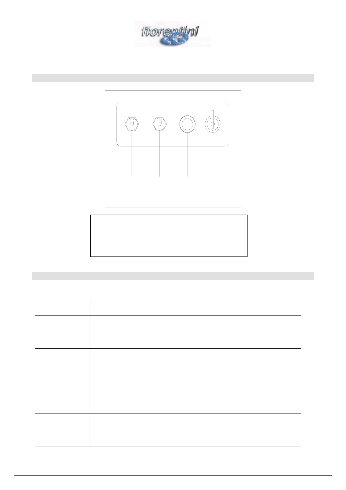
DASHBOARD CONTROLS
ALARM REPORTING
1 FLASH Fail of microswitch correct start sequence. This generally happens if at
start (key inserted) one of the direction microswitch is already closed.
2 FLASHES Battery is undervoltage or discharged. This alerts that the voltage isn’t
enough for a correct operation of the vehicle.
3 FLASHES Diagnostic code not used
4 FLASHES Electric motor circuit is sensed to be opened.
5 FLASHES Speed controller internal fault or electric motor has a fault to ground
(insufficient insulation level).
6 FLASHES Potentiometer Fault. This code is not active in case of a 2 wire connected
potentiometer.
7 FLASHES High temperature on power MOSFET unit. This alarm is active every
time there is a temperature of 75° C +/- 5°C on the MOSFET, The alarm
is active till the temperature doesn’t return below 75° C. During alarm
the max. current is reduced to safety level for the equipment reliability.
8 FLASHES The motor is sensed to be already in rotation when equipment is started
(key insertion). This happens for example, when the equipment is started
during descending a slope.
9 FLASHES Software has a fault.
1. Main Key Swich;
2. General Lamp;
3. Vacuum Motor Switch;
4. Brushes Motor Switch;
4 3 2 1

8
DASHBOARD SYMBOLS
0
Close(off) 1 On(first function)
Key Switch
Scrubbing Brush
Vacuum by Squeegee
Squeegee Lowering
Brush lifting
Squeegee Lifting
Brush lowering
Reverse
Increase by Traslation
Forward
General stop
9
USE OF THE MACHINE
SAFETY SYSTEM
The machine is equipped with double safety system for emergency stop:
•Mushroom push button . In emergency case press down this button.
•Socket (fig. 3), the same is also used to charge the battery. In emergency case, the socket must
be pull out from the plug using its handle (fig 4).
Before learning how to use the machine, the operator should be familiar with the use of this safety
system, to automatically use it in case of emergency. Never reset the safety system before having
solved the failure, if necessary with the help of a specialized technician.
Fig. 3
Fig.4

10
REVERSE SPEED SAFETY
To avoid operator crushing when machine run in reverse speed, there is a safety (fig.5), that is a
great surface lever. When it touch the operator it disconnect immediately the reverse speed and
insert forward speed. In this way we reduce at the minimum the shock or the operator crushing,
caused by a wrong manoeuvre. Fig. 5
BRAKE
The machine is provided with a parking and an emergency brake as well.(fig.7).
•The emergency brake is controlled by a lever (pos. 3).
•The parking brake is inserted pulling the lever. To disconnect it press down the lever.
Fig. 5
1. Battery Charge Plug;
2. Brake lever;
3. Solution adjustment lever;
1. emergency switch
2. speed adjusting
3. handle adjusting knob

11
INSTALLING THE BATTERY CHARGER
•Install the battery charger in a ventilated and dry place, far from heat sources and corrosive
environments.
•Protect the mains with a delayed switch or with a load fuse higher than the max. power
consumption of the battery charger.
•Observe the polarity of the battery socket (black cables are identified by symbols + and -).
CHOOSING THE DETERGENT SOLUTION
For a good cleaning of the floor, it is important to choose the proper detergent solution. If
necessary, ask the supplier or a competent person for the proper solution. Keep in mind that a too
strong chemical agent can compromise the long life of each machine. It is necessary to use a low-
sudsing detergent solution, or an antifoaming additive, in order not to damage the vacuum motor. If
it is impossible to get these products, use some vinegar to avoid foam, pouring 50cc of it in the
recovery tank before scrubbing.
STARTING AND PREPARING THE MACHINE
If the scrubber is connected to the battery charger (having finished the charge operation), detach the
battery charger plug from the socket (located on the machine) coming from the battery . Then,
connect the plug of the machine to this latter. Close the battery cover again. The machine should be
operated by turning the master key switch. Then, proceed with the water loading described under
the paragraph (par.). Perform the scrubbing once the work place has been reached.
SCRUBBING
The scrubbing operation is very delicate, as the operator’s experience must be used to decide upon
the brush type, the requirement of a possible double scrubbing operation, the right cleanser choice
and the right machine adjustments: if only one of these factors is inadequate, the scrubbing
operation can give very poor results. If the floor is very dirty or difficult to be cleaned, a double
scrubbing operation is recommended. In this first phase, the squeegee must be lifted and the brushes
must be in working position. Start the brushes and pass the machine over a surface of some tenth sq.
mt. Let the detergent solution on the floor to dissolve the dirt, then pass the machine again. For this
second machine passage, lower the brushes and bring the squeegee in contact with the floor.
Look at the floor after this second passage and decide if the scrubbing operation was enough or if an
additional operation is required.To perform the scrubbing procedure, turn the brush motor ignition
switch on, lower the brushes by screw jack switch, and operate the water adjusting lever. Water
should be metered so as to grant a well-wet surface after the brushes, however without causing any
splashes or overflows from the squeegee due to an excessive quantity of water. If double scrubbing
is not performed, lower the squeegee after placing the run switch in forward position. The squeegee
is lowered by means of the pedal. The vacuum motors are operated by means of the switch. Once
the scrubbing and drying procedure are finished, first of all close the water with the lever , then lift
the brushes by means of the pedal and the squeegee by means of the pedal. Finally, turn the motors
off.

12
Fig.6 Fig.7
SQUEEGEE ADJUSTMENT
The squeegee must be perfectly adjusted to get a perfect floor drying ( fig. 8).
The main caracteristic of this type of squeegee is to pick-up the water from the floor and convey to
the vacuum hose, but it must be paralle to the floor.To rightly adjust the squeegee operate as follow:
•Extract the key from the control dashboard to avoid accidental start of the machine.
•To adjust the pression operate the screw nut: unscrewing if you desire to decrease the pression,
or screwing if you desire to increase the pression.
•The right pressure is got when the edge of the rear blade touches the floor with a slating of
approx. 60°-45° referring to the floor. If it is necessary to change the blades slope, it is
necessary to operate the ring nuts.
Fig. 8
1. Emergency stop switch;
2. Advancement speed adjustment
throttle lever;
3. Handle position adjustment
knob;
1. Squeegee lifting pedal;
2. Brushes lifting pedal;
1. Squeegee inclination adjusting knob
2. Squeegee pression adjusting knob
13
BRUSHES REPLACEMENT
Before replacing the brushes, extract the key from the control dashboard, this avoiding that any
accidental ignition of some motors could cause damages
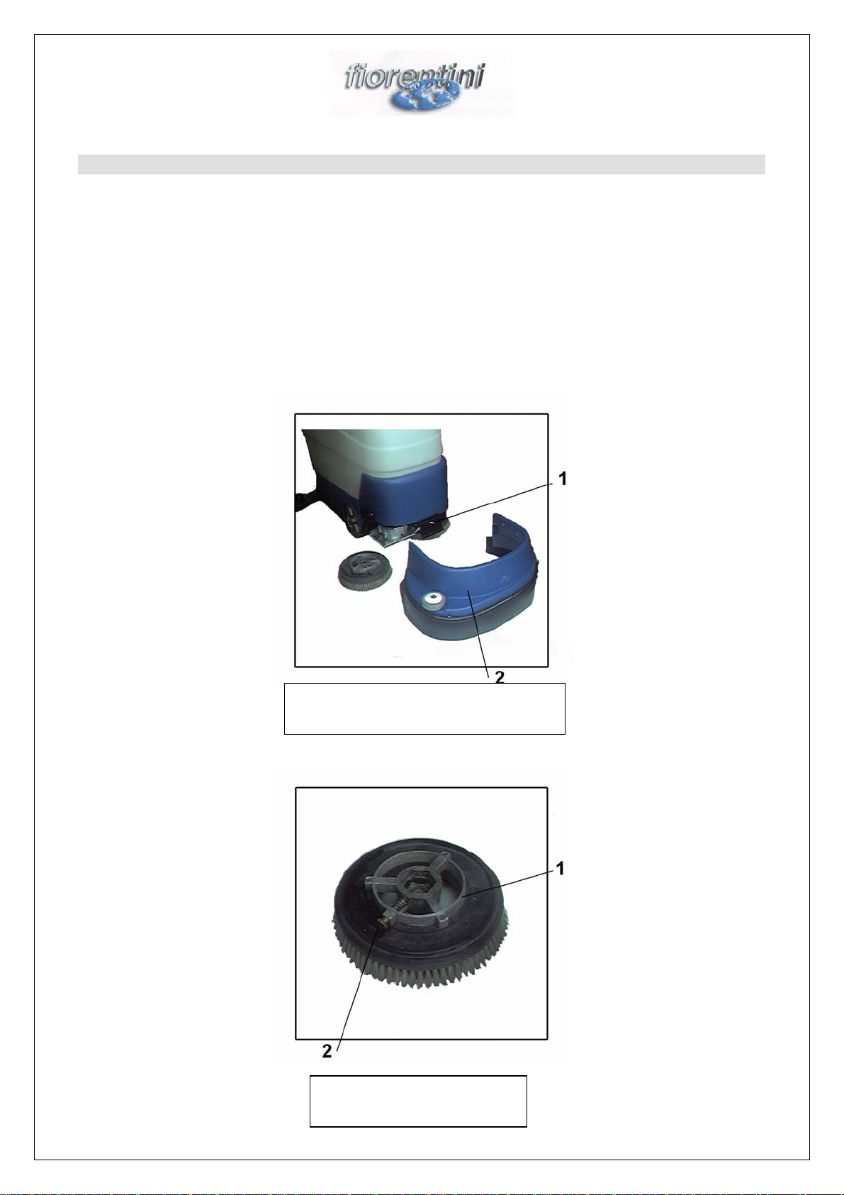
•First of all remove the knobs (fig.) by unscrewing them, then extract the brush covering carter
•Rotate each brush until its knob (fig.) can be reached, then extract it and remove the brush fallen
on the ground.
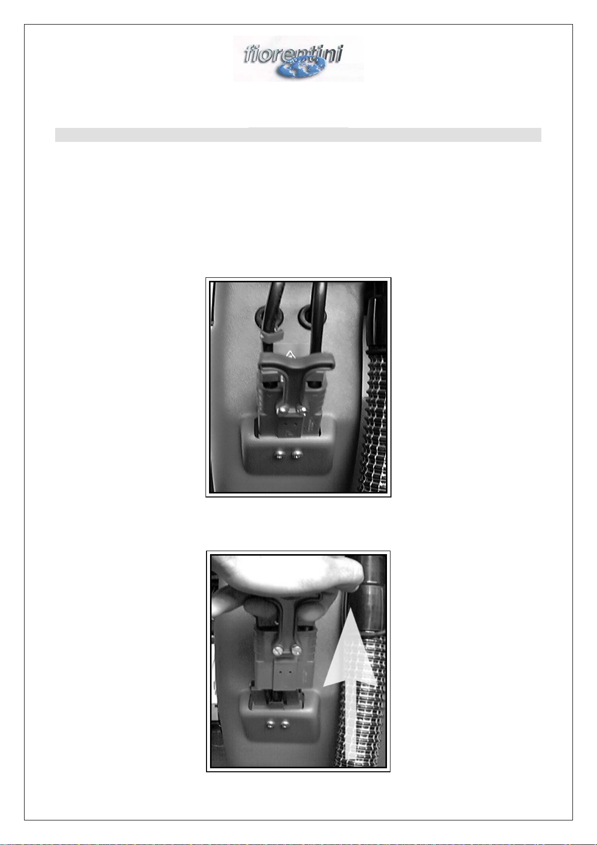
•To insert the new brush, place the hexagon of the female joint (fig.) under the male joint located
on the motor, then lift the brush vertically by rotating it until its automatic insertion has been
reached.
•After placing the brushes, insert the carter and screw the knobs again.
Fig. 9
Fig.10
1. Brushes covering carter knob
2. Brushes covering carter
1. Brush joint intake
2. Brush release joint

14
SAFETY, MAINTENANCE AND INSPECTION
GENERAL SAFETY RULES
Before using the machine ,instruct all operators to read carefully the charter ”SAFETY
STANDARDS “WARNING.
•The manufacturer can make any changes to the machine, for constructive or commercial
reasons, without being obliged to change the instruction manual at the right time according to
these modifications.
•The person responsible for the machine must adhere to CEE rules and to the local standards as
well, regarding the working environment for operator’s safety and health purposes.
•Before starting the machine ,always perform the preliminarily checks. The safety standards
which involve any dangers, mentioned in the manual text, can be recognized by the symbol:
CAUTION.
•Beyond the standard listed hereunder, the person responsible for the machine must comply with
the rules provided by the law in force regarding personnel’s safety and health in the working
stations. Furthermore, the person responsible for the machine must instruct the operators on
what follows:
1. Safety and accident prevention standards
2. Specific standards regarding the machines
3. Location on the machine of emergency pushbuttons or similar mechanism, for a
prompt operation. The fixed or movable protections(carters)should always remain in
their position, correctly fixed with perfect integrity during all procedures regarding
the normal operation. If, for any reason ,the carters are removed, their efficiency
should be restored before restarting the machine.
4. Use the machine only under technically unexceptionable conditions and in
compliance with its destination, by observing the safety and prevention standards
according to the prescriptions contained in the instruction and maintenance
handbook.
5. Remove (or let remove) immediately any failures which could compromise the
safety.
6. The machine is designated to be used as a scrubber ;any other different use doesn’t
not comply with its destination. the manufacturer/supplier takes no responsibility for
any consequent damage.
•DANGER
It is absolutely forbidden to suck inflammable and or toxic liquids and powders
•DANGER
It is dangerous and absolutely forbidden to touch the lower part of the machine with the hands
when some parts are moving. Should it be absolutely necessary, remove the main key from the
control dashboard.
•CAUTION
On this rider on machine the rotating headlight should constantly operate and must be switched
on when turning the key switch.
CAUTION
Keep in mind the following standards; failure to adhere to these rules can endanger the life of the
operator or of other people. Always keep a sufficient distance from the sidewalk edges and from
large differences in height of the floor where the machine can fall; never adopt a work tecnique that

15
can compromise the stability of the machine. Never pass through slopes in trasversal direction;
when going through a downhill road, always adjust the speed to the environment conditions. Do not
turn the machine at excessive speeds, particularly if the floor is not flat.
CAUTION: DANGER
Never operate the machine when stopped for special operations (setting up, maintenance, etc.).
Before starting the work, check for any possible visible defects on the safety devices, and the
correct operation of the emergency stop pushbutton or of the equivalent mechanism . Never operate
the machine when the control panel indicates defective tools, warning lights, etc.
MAKE SURE THAT:
- No strangers are present near the machine
- No strange objects (appliances, cloths, etc.) are on the machine
- The machine does not emit strange noises after its starting; if so, stop it immediately and detect the
cause.
All doors and protections are regularly closed.
Never let approach strangers near the machine. Use, maintenance and repair of the machine are
allowed only to operators authorized by the person responsible of the machine, who knows the
manual contents. These operators should be persons physically and intellectually fit for this work,
not under alcohol or drug effects.
MAINTENANCE INSTRUCTIONS
During the scrubbing operation, the maintenance of the machine and the replacement of parts, it is
necessary to extract the ignition key.
Instructions for battery:
- when charging the battery, let the battery cover open
- do not use free flames and do not smoke near batteries
- caution: liquid is corrosive
- do not cause sparks near the batteries
- battery gases are explosive
- do not cause any short-circuits
- do not invert polarities
GENERAL NOTE
For any maintenance, revision or repair, engage qualified personnel or call an authorized workshop.
Use only original fuses with the prescribed current intensity. In case of a power failure, disconnect
the machine or the plant immediately. The electric installation should be periodically inspected and
checked. Any possible failure, such as detached connections and burnt cables should be
immediately removed.
CAUTION
To clean the machine, use aggressive detergent solutions, acids, etc. only when necessary and with
special care. Adhere to all instructions of the detergent manufacturer. Use protective clothes
(overalls, gloves, protective glasses, etc., see CEE standards).
OPERATIONS ON THE ELECTRIC INSTALLATION
The operations on the electric installation can be performed only by QUALIFIED
ELECTRICIANS, instructed in the electric characteristics of the machine and in accident
prevention rules.
CHECKS
The machine must be inspected by a technician, who checks the safety conditions of the machine
and any possible damages or defects visible from outside:
- before setting the machine at work
- after appropriate time intervals
- after any changes or repairs
- safety device control

16
SAFETY DEVICE CONTROL
All six month, check the efficiency of the safety devices, the inspection should be performed by
qualified personnel of FIORENTINI s.r.l. or authorized by it. To grant the efficiency of the safety
devices, the machine should be overhauled by a technician of FIORENTINI every 5 months.
ANNUAL CHECK
The responsible person should perform an annual check to determine if the machine complies with
the technical safety standards. After this check, the responsible person should apply a test plate on
the machine.
INFORMATION FOR USING THE MACHINE IN EXPLOSIVE ATMOSPHERE
The machine has not been designed to work in environments in which explosive gas, powders or
steams can be generated.
DANGER
To drain the liquids used for floor scrubbing, follow the local standards concerning the elimination
and purification.
INFORMATION CONCERNING THE MACHINE DEMOLITION<R>(CEE STANDARDS)
In case of machine demolition, it is important to subdivide the different types of materials
composing the machine and deliver the batteries to operators authorized to their elimination.
MAINTENANCE SCHEDULE

17
During the cleaning and the maintenance of the machine remove the key.
DAILY
•Clean the recovery tank and the filter of the vacuum motors.
WEEKLY
•Check for the cleaning of the suction pipes and of the squeegee
•Check the state of the rubber squeegee blades
•Check battery water level
MONTHLY
•Check the filter of the clean water tank
ALL SIX MONTHS
•Check batery connections
EACH YEAR
•Check the brush state of each motor
AFTER TWO YEARS
•Check safety systems
•Check electric installation
BATTERY
•During the battery charge the battery cover must be always open
•Don’t smoke close to the batteries
•Be carefull to the acid because is dangerous
•Don’t generate sparkles close to the batteries
•The batteries are esplosive
•Don’t invert polarity
BATTERY TECHNICAL CARACTERISITICS
BATTERY CHARGER TECHNICAL CARACTERISTICS
SQUEEGEE BLADE REPLACEMENTS
IN V 230, Hz 50, A5
OUT V 24
,
A25
TENSION V 6
CAPACITY 220 A/h
WEIGHT 30 Kg
SIZE 26,5x17x26 cm

18
The squeegee blades should be replaced when the contact edge becomes worn; the perfection of the
edge is essential for a perfect drying. To replace the blades
•The squeegee should be demounted from the machine and placed on the desk.
•Now, remove the screws (fig) both on the front part and on the rear part of the squeegee, the
steel straps and remove worn rubber blades
•Perform the inverse procedure and assemble the new blades, then adjust the squeegee.
Fig. 11
VACUUM MOTOR MAINTENANCE
1. squeegee body
2. squeegee blades
3. squeegee straps
19
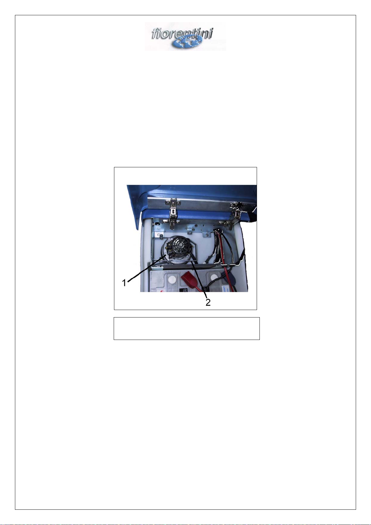
The vacuum motors must be checked and cleaned. The brushes should be checked all six months
and replaced, if necessary. After removing the key from the dashboard, descrew the screw in the
vacuum motor space, open it, unhook the hooks and detach the plug . In this way, it is possible to
extract the motors and release the sponge filter under the motors that can be extracted, cleaned and
replaced. Check the suction fan from the hole located in the front part of the vacuum motor. By a
visual check, the fan should appear undamaged and well-cleaned. To check the brushes, first of all
remove the plastic cap, then unscrew the screws and remove the two plastic supports of the
brushes. Once checked and replaced (if necessary), the brushes can be easily remounted, by
reassembling all elements until the initial situation has been reached.
Fig. 12
CAUTION
Each maintenance and repair operation not described under the “ordinary maintenance”
should be performed by qualified personnel authorized by FIORENTINI s.r.l. only.
1. Accelerator Motor;
2. Vac Motor;
This manual suits for next models
1
Table of contents
Other FIORENTINI Scrubber manuals

FIORENTINI
FIORENTINI L14 Installation and maintenance instructions

FIORENTINI
FIORENTINI ECOPRO40 User manual

FIORENTINI
FIORENTINI TERMINATOR-1000 User manual

FIORENTINI
FIORENTINI JOLLY 13 User manual

FIORENTINI
FIORENTINI ET 65-75 User manual

FIORENTINI
FIORENTINI PINKY 26 Operating instructions

FIORENTINI
FIORENTINI SCOIATTOLO 75 User manual

FIORENTINI
FIORENTINI L14 Installation and maintenance instructions

FIORENTINI
FIORENTINI ECOMINI 430 Specification sheet

FIORENTINI
FIORENTINI ECOSMALL55-N1 Operating instructions


