FIORENTINI 142TP-GB Operating instructions

ING. O. FIORENTINI S.p.A.
INDUSTRIAL CLEANING MACHINES
SCRUBBER MACHINE
Mod. I42/60 TPB - GB
OPERATING AND MAINTENANCE
MANUAL

CONTENTS
1.
GENERAL INFORMATION
1.1. Symbols used.......................……......………………………………………………page
4
1.2. Notes…….....…..............…......................................................................................
4
1.3. Consulting the manual……............................................….........………….…………
4
1.4. Warranty..................................................................................................................
4
1.5. Declaration of Conformity……………………………….…........................................
5
2.
MACHINE CHARACTERISTICS AND TECHNICAL DATA
2.1. Identification………..................................................................................................
7
2.2. Description and components...….…………………………..………….….……...........
7
2.3. Technical data sheet…………………………………………………….….…….…........
9
3.
SAFETY
3.1. Recommended machine use……....……………....…....……………..…………........
10
3.2. Misuse……………………….…..………………………………………………………....
10
3.3. Recommended equipment………………………………………….…………………….
10
3.4. Operator qualifications..…………............................................................................
11
3.5. Safety and warning devices …………………………………………………………......
11
3.6. Safety systems...................................................................................................….
12
3.7. Safety diagnostic signalling ……………………………..……………………………….
12
3.8. Residual dangers ………………………………………………………………………….
14
3.9. Safety signals…………………………………………………………………..…………..
15
4.
START-UP AND OPERATION INSTRUCTIONS
4.1. Transport and handling…….........................................................….....................…
17
4.2. Storage…………………………………………………….…….....................................
17
4.3. Machine unpacking..........................................................................…………………
17
4.4. Unpacked machine handling .........………………………………..………..…….........
18
4.5. Control and monitoring devices………………………….……………………………….
18
4.5.1. Dashboard…………………………………………………………………………………
18
4.6. Operation………………………………………...………………………………………...
20
4.6.1. Machine preparation and start-up……………..….…………………………………….
21
4.6.2. Choosing the right detergent………………………………….……………………..….
21
4.6.3. Pedal and lever controlled functions ………….……………………………………….
21
4.6.4. Squeegee adjustment ………………………………….………………………………..
22
4.6.5. Water draining……………..…………………………………………………..………….
23
4.6.6. Brushes replacement ……………………………………………………………………. 24
4.6.7. Squeegee replacement……………………………………………..…………………… 25
4.6.8. LPG bottle replacement ……………………………..………………………………….. 26
Congratulations on your choice!
Thank you for having chosen to purchase a product by FIORENTINI S.p.A., a world-
leading manufacturer and distributor of industrial cleaning machines.
Our long-standing experience and acquired know-how are the best guarantee of the
technical quality of your purchase; all our products are built from top quality materials to
ensure maximum reliability, sturdiness and functionality and to meet the requirements of
even the most demanding customers. FIORENTINI was recently granted the quality
system certificate to certify compliance with the requirements of UNI EN ISO 9001.
Feel free to contact us with any technical or commercial inquiry; we will be happy to
supply any details and information that you may need.

5.
MAINTENANCE
5.1. Routine maintenance table……………..……………...............................................
27
5.2. Battery maintenance………………………………………………………………………
27
5.2.1. Hydrometrics.……………………………………………………………….……………
28
5.2.2. Water topping-up ………………………………………………………………………..
28
5.2.3. Charge limits………………………………………………….………………………….
28
5.2.4. Standby or inactive batteries …………………………………………….…………….
28
5.2.5. Maintenance LPG/Gasoline engine………..………………………………………….
28
5.3. Suction motor maintenance………………………………………………………………
29
5.4. Wiring system checks…………………………………………………………..…………
29
5.5. Summary table of the recommended checks…………………………..……………….
30
5.6. Maintenance log…………………………………………………………………………….
31
6.
TECHNICAL ASSISTANCE
6.1. Technical assistance contact information..............................…………....................
32
6.2. Claim report ……………………………..…………………………………….……...……
32

GENERAL INFORMATION
I42 I60 TP - GB
Rev. 000
27/11/2017
4/34
1. GENERAL INFORMATION
1.1. SYMBOLS USED
This symbol is used to alert the operator to important procedures or precautions to be
followed in order toprevent damagesto usersor themachine
This symbol is used to alert the operator to important general information.
1.2. NOTES
1.3. CONSULTING THE MANUAL
This manual deals exhaustively with all the issues considered necessary for an easy and safe use of the
machine, in compliance with European Directives on product safety.
We therefore suggest to all authorised operators to carefully read this manual throughout and
contact FIORENTINI in case of any doubt. This manual should also be used for reference whenever
there are doubts concerning a procedure or operation to carry out or to train new operators.
In print, pictures and drawings can look slightly different from actual machine parts, without however being
perceived as confusing.
Special symbols and bold and/or Italic fonts are used to highlight important information, particularly
concerning safety.
The current revision code is indicated in the bottom left corner of every page. The list of revised pages is
shown at the end of the manual.
1.4. WARRANTY
Warranty terms and conditions are stated here below unless otherwise specified in the order confirmation.
SCOPE OF THE WARRANTY
The machine has been designed and built for trouble-free use over several years. However, if any
malfunctioning is observed during the warranty period, FIORENTINI S.p.A. undertakes to repair or replace
free of charge any parts showing breaks or early wear due to faulty materials, working defects or incorrect
assembly. The manufacturer warranty will not cover any parts whose early breaking or wear-and-tear are caused
by:
FIORENTINI S.p.A. is the owner of this manual.
The reproduction of all or part of this manual or its transmission to third parties by any
mechanical or electronic system or otherwise is forbidden without a written authorisation
by the manufacturer. This manual is supplied to the customers in a single original copy
unless otherwise specified at the time of ordering.
This manual is supplied as an integral part of the machine and if the machine is transferred to a new owner,
this manual should also be transferred. This manual should be stored at a safe location throughout the
machine working life. The purchaser is responsible for making this manual available to all users. If this manual
islost, aduplicateshouldbe obtainedfrom FIORENTINI.
FIORENTINI S.p.a. will not be held responsible for any damages to persons and/or property resulting from
failure to comply with the instructions in this manual.
FIORENTINI reserves the right to introduce any required technical and commercial changes without giving
any notice. Therefore, any data and information contained in this manual may be changed and/or updated.

GENERAL INFORMATION
I42 I60 TP - GB
Rev. 000
27/11/2017
5/34
Failure to observe the instructions contained in this manual;
Tampering or alterations introduced without FIORENTINI’s specific approval;
Use of non-original spare parts.
Wear parts for use as: brushes, blades, squeegee, etc.
For installed electrical parts and commercially available parts, FIORENTINI will extend to purchasers the
same warranty terms granted to FIORENTINI itself by the parts' suppliers.
WARRANTY VALIDITY
The Ing.O.Fiorentini S.p.A. general terms conditions also apply to the warranty.
The manufacturer cannot be held responsible in any way for damages resulting from unauthorised
modifications made to the appliance, from the use of unsuitable brushes and accessories and after use of
the device other than that intended.
WARRANTY APPLICATION TERMS
Defective components must be returned to FIORENTINI in order to establish the causes of any observed
defects and determine warranty applicability. Repairing and replacement under the warranty will be carried
out on FIORENTINI’s premises, by subcontractors or on the customer's premises. For work carried out on
site, the customer will have to provide power sources, special equipment and auxiliary personnel and cover
FIORENTINI personnel's travelling and accommodation expenses and meals.
PRODUCT RETURNS
In case of parts to be returned for replacement or repairs under the warranty, a written authorisation must be
obtained in advance from FIORENTINI's Technical Assistance Department.
All defective parts must be carefully repacked in order to avoid damages during transport. Products must be
returned on a free-on-board basis, complete with:
Serial number read from the equipment ID plate (point 2.1);
Item code and installation position of the returned parts, read from the spare part list (point 7.2);
Detailed description of the observed defect and conditions under which it became apparent.
In case of defective electric or electronic components,
please return the parts separately from other materials,
so that waste
containing dangerous substances can be separated and
Waste Electrical and Electronic Equipment (WEEE) can be
recycled according to the 2002/96/EC Directive.
Any parts acknowledged as being under the warranty will be returned on a free-on-board basis; replaced
parts will remain the property of FIORENTINI.
EXCLUSIONS
The warranty will not cover materials and components exposed to normal wear and those whose working life
cannot be established beforehand.
A missing machine data plate will imply the immediate loss of any warranty rights.
1.5. DECLARATION OF CONFORMITY
The Declaration of Conformity is supplied with the purchased machine and the use and maintenance
manual.

GENERAL INFORMATION
I42 I60 TP - GB
Rev. 000
27/11/2017
6/34

MACHINE CHARACTERISTICS AND TECHNICAL DATA
I42 I60 TP - TG
Rev. 000
27/11/2017
7/34
2. MACHINE CHARACTERISTICS AND TECHNICAL DATA
2.1. MACHINE IDENTIFICATION
An adhesive machine identification label containing indelible “CE” marking details is affixed on the inside of
the machine front nose/control panel.
The label must never be removed and should always be kept legible. If the label is
damaged a duplicate should be ordered. The machine may be sold without the label.
2.2. DESCRIPTION AND COMPONENTS
The scrubber machine I42TP-GB has been designed to clean flat surfaces by means of washing followed by
washing water suction. The electric drive system is equipped with a set of batteries supplying power to the
brushes motor, the brush plate jack and the suction motor.
The machine I42TP-GB is manufactured with a three brush, front scrubbing unit and an (optional) single
roller sweeping and scrubbing unit, designed to clean surfaces with water and detergent. When the machine
moves forwards, the squeegee or back brush, in contact with the floor, takes up any water by suction for its
subsequent delivery to the recovery tank.
When the ignition key is turned, the machine is powered on and prepares to scrub and dry the floor. The
machine travelling direction can be chosen via the special lever selector.
The control panel controls all machine functions. In particular, it is possible to:
start the machine scrubbing function;
select the forward or backward movement direction;
display the battery charge;
lower the brush plate and start the brushes;
start vacuum suction;
turn the machine on and off.
The machine load-bearing structure consists in a steel frame submitted to electrophoretic paint finishing
treatment to prevent corrosion which might affect machine reliability.
The main components of the machine are:
carbon steel frame treated by electrophoretic paint finishing;
LLDPE plastic washing solution filling tank;
LLDPE plastic recovery tank for washing effluents complete with inlet and outlet hoses;

MACHINE CHARACTERISTICS AND TECHNICAL DATA
I42 I60 TP - TG
Rev. 000
27/11/2017
8/34
front scrubbing unit with three rotating brushes;
central sweeping unit with cylindrical brush (optional);
squeegee;
two motor-driven drive wheels;
one idle steering front wheel;
adjustable steering assembly;
driving seat.
In consideration of recent EU concerns regarding product safety, FIORENTINI designed and built this
machine in compliance with the safety and health requirements provided by applicable Directives. The high
quality of the materials used, the applied advanced technology and FIORENTINI’s long-standing experience
are a guarantee of the performance and reliability of this machine. Each machine is submitted to rigorous
testing during construction and to a thorough final test.

MACHINE CHARACTERISTICS AND TECHNICAL DATA
I42 I60 TP - TG
Rev. 000
27/11/2017
9/34
2.3. TECHNICAL DATA SHEET
The above-mentioned specifications are not binding on the manufacturer and may therefore
be changed without notice. FIORENTINI can be contacted at any time for further information
(point 7.1.).
UNIT OF MEASURE CONVERSION TABLE
Length
1 inch = 1” = 25.4 mm
Power
1 kW = 1.36 CV = 1.34 BHP
Temperature
T (K) = t (°C) + 273 / t (°F) = 1.8 t (°C) + 32
Pressure
1 bar =100 kPa = 14.5 psi
SPECIFICATIONS
I42 TP - GB
I60 TP - GB
Power supply
Kubota motor mod.:DF752
Drive system
160cc idraulic motors on the two rear axles
Scrubbing width
1250 mm
1500 mm
Squeegee width
1400 mm
1650 mm
No. of brushes
3x Ø380mm
3x Ø460mm
Brush pressure
0-120 kg
0-120 Kg
Hourly output
15000 m2/h
18000 m2/h
Solution tank
260 l
Recovery tank
260 l
Water lift
166 mbar
Forward speed
0-12 Km/h
ENGINE & MOTOR SPECIFICATIONS
Drive motor
2x160cc
Suction motor
2x850w
Brush motor
3x80cc
DIMENSIONS
Length
2070 mm
Width
1400 mm
1650 mm
Height
1370 mm (1510 mm with flashing light)
Empty weight
830 Kg
850 Kg
Drive
On-board operator
Min aisle width for U-turns
2900 mm
3020 mm
Max. gradient with full load
10%
Noise
85 dB(A)

SAFETY
I42 I60 TP - GB
Rev. 000
27/11/2017
10/34
3. SAFETY
3.1. RECOMMENDED USE
This is a floor scrubbing machine designed and built for use in industrial
environments, to carry out wet scrubbing, drying and effluent collection on flat
horizontal surfaces or surfaces with a gradient not exceeding 10% at speeds not
exceeding 3 km/h. U-turns are prohibited on any gradient slopes.
3.2. MISUSE
Machine operation by unauthorised personnel;
scrubbing uneven and/or bumpy surfaces;
scrubbing sloping surfaces;
scrubbing surfaces whose gradient exceeds 10%;
doing U-turns on any (even minimal) gradient slopes;
using the machine in environments containing dangerous substances, and in
particular, in explosive atmospheres or inadequate microclimatic conditions;
cleaning machine surfaces in the presence of flammable substances;
the machine may not be used as a means of transport for people or other
vehicles;
altering or tampering with safety devices;
charging batteries at not sufficiently ventilated locations;
failure to comply with applicable safety standards currently in force;
fitting equipment/devices likely to interfere with machine operation;
introducing changes or alterations not authorised by FIORENTINI;
using acid solutions likely to damage the machine;
failing to comply with use and maintenance manual specifications.
The informative labels provided on the machine should be carefully read and should
not be covered for any reason. FIORENTINI shall not be liable in any case for any of
the above not recommended uses of the machine (instances of misuse).
3.3. SUGGESTED EQUIPMENT
To make the best use of your machine, equipment specially designed and tested by Fiorentini and original
spare parts should be used. The Design Department of FIORENTINI S.p.A. is willing to meet any design
requirements concerning parts and components for personalised applications.

SAFETY
I42 I60 TP - GB
Rev. 000
27/11/2017
11/34
3.4. OPERATOR QUALIFICATIONS
The table here below specifies the operator qualifications required for each operation to carry out.
Type of Operation
Operator Qualification
Machine operation/control
Trained operator
Installation/removal
Fiorentini technician
Mechanical parts maintenance
Fiorentini technician
Electrical parts maintenance
Fiorentini technician
Cleaning maintenance
Trained operator
Dismantling and scrapping
Fiorentini technician
The personnel in charge of operating the machine should be specifically trained, particularly in regard to
safety issues; machine operators must have read and become familiar with this manual.
FIORENTINI declines all responsibility for accidents involving persons or property caused by
not adequately skilled, unauthorised operators.
3.5. SAFETY AND WARNING DEVICES
It is strictly forbidden to tamper with, remove or deactivate safety and warning
devices while the machine is in operation.
The efficiency of safety and warning devices should be regularly checked (see point
5.1.).
Seat emergency control
This machine is equipped with an emergency microswitch located under the
driver's seat to prevent machine operation unless an operator is sitting in
the driver's seat.
Float timer
The machine is equipped with a timer for the float to prevent vacuum motor
power on and power off.
Filter
The machine is equipped with an anti-foam filter
Solenoid valve
The machine is equipped with a solenoid valve preventing water from
flowing out before brushes power-on.
Warning devices
The machine I42-60 TP-GB is equipped with several warning devices to
alert anyone who happens to be within the machine working range:
a horn-type acoustic signal to warn any persons who are near the
machine during normal use;
an intermittent acoustic signal (buzzer) to warn any nearby persons
while the machine is reversing;
a visual signal (yellow flashing light) to indicate that the machine is in
operation.

START-UP AND OPERATION INSTRUCTIONS
I42 I60 TP - GB
Rev. 000
27/11/2017
12/34
3.6 SAFETY SYSTEMS
The machine is equipped with the following safety systems:
Emergency stop button: A red emergency stop button is provided on the machine control panel.
Before using the machine, the operator should become familiar with its safety devices, to be able to
automatically actuate them in an emergency. The safety devices should never be reset before
having corrected the cause of an observed problem; contact a skilled technician if necessary.
Presence-sensing device: The machine is equipped with a presence sensor integrated in the seat.
Without an operator on board, the machine will not start, and if the operator gets off the scrubbing
machine without having first turned the key switch to its 0 position, the machine will shut down. To
re-activate it, the operator must sit in the driving seat, turn the key switch to its OFF position, wait a
few seconds and then return the key switch to its ON position.
Float: The recovery tank is equipped with a float which prevents suction in case of overfilling; in this
case, to restart the machine the tank must be emptied first (see the WATER DRAINING section).
Solenoid valve: The machine is equipped with a solenoid valve to let scrubbing water through only
after the brushes have been powered on, so as to prevent accidental leaking.
Float timer: The machine is equipped with a timer on the waste water float to stop suction motor
power on and power off due to wave-like water motion.
3.7 SAFETY DIAGNOSTIC SIGNALLING
The machine has a display unit on which basic information concerning the machine work cycle can be
viewed. The meaning of the various symbols that can be displayed is explained here below.
Upon power-on, the screen lights up. In this order:
A test is performed to check the correct
operation of all the LCD display segments.
The battery rated voltage, expressed in
volts, is displayed in the numerical part of
the display screen.
After initialisation completion, the display screen
shows the per cent charge value (between 0% and
100%) in the top segment bar and the hour counter
state in the alphanumerical part of the display unit

START-UP AND OPERATION INSTRUCTIONS
I42 I60 TP - GB
Rev. 000
27/11/2017
13/34
When the brushes are started the hour counter is
enabled. The hourglass icon starts flashing.
After reaching the minimum charge level the battery
icon starts flashing.
After 300 hours of operation, the spanner icon lights
up to remind the user that a service is due. Servicing
and icon resetting must be carried out by
Ing.O.Fiorentini S.p.A. authorised personnel.
Optional. The bottom LED bar shows the solution
tank filling level.

START-UP AND OPERATION INSTRUCTIONS
I42 I60 TP - GB
Rev. 000
27/11/2017
14/34
Finally, the machine behaviour when the recovery tank has reached its maximum level is described. A float
switch is activated which sends a signal to the battery load indicator. This will disconnect power to the
suction devices. It is no longer possible to use the suction devices until the machine is restarted. However,
until the tank is emptied, the raised float switch will continue to stop power input to the suction motors.
In order to prevent suction disabling every time the float is lifted even slightly (e.g. due to wave-like liquid
motion in a not yet completely filled tank), the switch signal is only accepted by the electronic board when
this is active for at least 5 seconds. This activation delay should be borne in mind when efficient float
behaviour needs to be checked.
3.8 RESIDUAL DANGERS
Ever since the design phase, FIORENTINI has analysed all the possible dangers related to machine use in
order to eliminate or at the very least minimise the risk of injuries for machine operators. In order to minimise
the risk associated with residual dangers, danger signs and indications of accident-prevention systems and
procedures have been provided for machine operators.
DANGER OF CRUSHING
Crushing risks are possible:
during scrubbing brushes replacement;
during battery charging should the battery cover suddenly snap shut
in the central battery housing compartment.
During side brush replacement, the operator must ensure that the ignition key is not in its slot in the
control panel, to prevent unwanted machine starts. During battery charging, the operator must keep
all body parts out of the battery compartment.
DANGER OF
CRUSHING/SHEARING
Crushing and shearing risks are possible:
during squeegee adjustment.
During squeegee adjustment, ensure that no-one close to the machine is able to operate the device
up- and down-stroke controls.
DANGER OF OVERTURNING
Machine overturning is possible:
during normal machine operation when going over slopes with a higher gradient than the
recommended value and when the machine is used to clean uneven/bumpy surfaces (see
3.2).
Do not use the machine to scrub surfaces with gradients exceeding 10% at
speeds exceeding 3 km/h or bumpy or uneven surfaces likely to affect the
stability of the machine.
FIORENTINI declines all responsibility for accidents involving persons or property caused by
machine use on stability-affecting floors. The buyer must provide suitable signage to inform
the user about the condition of the working surfaces.

START-UP AND OPERATION INSTRUCTIONS
I42 I60 TP - GB
Rev. 000
27/11/2017
15/34
3.9. SAFETY SIGNALS
The safety signs include symbols indicating:
DANGER
Danger symbols are triangular with black
pictograms on yellow background
PROHIBITION
Prohibition symbols are round with black
pictograms on white background and a red
stripe
What is it?
This symbol indicates a crushing risk caused by the presence of
moving parts inside the machine or by the operator actuating
moving parts inside the machine (e.g. covers and partitions).
What to do?
During installation or maintenance make sure that the ignition key is
not in the dashboard. Ensure that any stops provided for moving
parts are in the right position and carry out their design function
correctly.
What is it?
This symbol warns that it is forbidden to remove safety guards from
around moving parts.
What to do?
During installation/maintenance, before removing guards always
ensure that the starter key is not in its slot in the control panel. Keep
all body parts out of the machine during work.
What is it?
Symbol warning of explosion risks during battery charging due to the
released hydrogen.
What to do?
During battery charging, ensure that the machine is under a suction
hood or in a ventilated area and keep it away from heat sources and
corrosive substances.
What is it?
Symbol warning of fire risks during battery charging due to the
released hydrogen.
What to
do?
During battery charging, ensure that the machine is under a
suction hood or in a ventilated area and keep it away from
heat sources and corrosive substances.
What is it?
This sign indicates that it is forbidden to wash the concerned part of
the machine with pressurised water jets.
What to do?
Do not direct high-pressure water jets against guards or covers
carrying this symbol.

START-UP AND OPERATION INSTRUCTIONS
I42 I60 TP - GB
Rev. 000
27/11/2017
16/34
The machine areas implying residual risks are pictured here below.
If any signs become damaged, the purchaser must replace them with identical
signage. It is strictly forbidden to remove or tamper with these signs.

START-UP AND OPERATION INSTRUCTIONS
I42 I60 TP - GB
Rev. 000
27/11/2017
17/34
4. START-UP AND OPERATION INSTRUCTIONS
4.1. TRANSPORT AND HANDLING
The machine is delivered to the purchaser fully assembled and contained in a special package. A black
arrow on the package indicates the centre of gravity. Truck or pallet truck forks must be inserted so as to
ensure that the black arrow is centred between the forks. The package must be handled carefully. Do not
stack packaged items.
If agreed with the purchaser, the machine can be delivered unpacked, on a pallet and secured with straps.
The purchaser should check upon delivery that the machine has not been damaged during
transport and that all the material listed in the shipping documentation has been received;
otherwise, the forwarders and manufacturer should be promptly informed.
Unless otherwise agreed, purchased goods will travel at the purchaser's own risk.
Handling should be carried out with suitable lifting equipment, as shown in the following table. Always ensure
that the forks of the lift truck, or the harness straps, are positioned so as to ensure that the arrow printed on
the package is centrally positioned on the lifting equipment. The anchoring and/or harnessing points are
arranged so as to ensure that, during lifting, the machine is always steady and well balanced.
Type of packaging
Handling equipment
Paperboard or plywood box on
a pallet
Fork lift truck
None
Fork lift truck or truck crane with a two-strap balance harness
The harness straps used must be suitable for the load to lift. All handling
operations should be carried out at very slow speed to prevent load swinging and
loss of stability. Any operation performed incorrectly may damage the machine and
expose operators to dangers.
Refer to the technical data sheet for machine dimensions and weight. Machine handling
should be carried out by authorised personnel trained for lifting equipment use only.
4.2. STORAGE
If not immediately installed, the machine should be stored at a covered, dry location to ensure the perfect
efficiency of all its parts. Relative humidity must be below 80% and the storage temperature must be
between 15°C and 35 °C.
4.3. MACHINE UNPACKING
Cut the straps bearing in mind that they might spring back
Remove the staples fixing the carton to the pallet
If the crate is made of plywood, remove the staples from each side and the base of each panel
Cut the straps that secure the machine
Place the machine on the floor

START-UP AND OPERATION INSTRUCTIONS
I42 I60 TP - GB
Rev. 000
27/11/2017
18/34
4.4 UNPACKED MACHINE HANDLING
Inspect the machine and install the batteries if not already installed
To prepare the machine for short distance handling after use, disconnect the battery cables and
remove the brushes and the squeegee; for longer-distance transport, the machine should be
repacked in its original packaging.
4.5. CONTROL AND MONITORING DEVICES.
4.5.1. DASHBOARD
A number of controls are provided on the control panel (buttons, switches, levers, indicators, warning lights)
to start, stop and monitor machine functions during cleaning operations. Each is associated with a pictogram
to identify the controlled function. The control panel layout is shown here below to help you identify each
control position.
1
Battery charger indicator - Diagnostics
2
Flashing Light ON/OFF switch
3
Front light ON/OFF switch
4
Horn button
5
Sweeping Switch
6
Motor Suction Switch
7
Squeegee Hydraulic Jack ON/OFF Switch
1
2
3
4
55
66
7
8
9
10
11
12
13
14
15

START-UP AND OPERATION INSTRUCTIONS
I42 I60 TP - GB
Rev. 000
27/11/2017
19/34
8
Brush plate Hydraulic Jack ON/OFF Switch
9
ON/OFF main Switch
10
LPG/Gasoline Switch
11
Fuel Level Indicator
12
Oil Pressure Switch Indicator
13
Starting Battery Indicator
14
Engine Water temperature Indicator
15
Starter (Knob)
1
Accelerator lever
2
Solution water lever
1
2

START-UP AND OPERATION INSTRUCTIONS
I42 I60 TP - GB
Rev. 000
27/11/2017
20/34
Table in which the meaning of the pictograms in the control panel is specified:
Off
Switched off
On
Switched on (first operating
function)
Fast gear
Slow gear
Gradual increase/decrease
of solution flow rate.
4.6. OPERATION
Scrubbing operations are highly critical and specific experience will help you choose the right type of
scrubbing brush and detergent and determine whether or not a double cleaning cycle is necessary.
To perform the scrubbing operation, start suction and lower the squeegee by pressing the special key; when
the machine first moves forwards, the brush plate will be automatically lowered to the floor. Brush rotation
will start simultaneously. As soon as the machine stops, after a delay of approximately 5 seconds, the brush
plate will be lifted and the brush rotation will stop. Adjust the solution flow rate via the special lever.
After scrubbing completion, before drying completion, turn the water tap off.
When the brush motors stop, the solenoid valve is operated to cut off the solution flow. In this way, it will not
be possible to accidentally allow all the solution to leak out to the floor.
If a floor is very dirty, a two-step cleaning action is recommended - including a first step with the squeegee in
its raised position and the scrubbing brushes in their working position; after starting the brushes and
operating the water lever, the first cleaning cycle will be performed over a surface of a few dozen square
metres. The cleaning solution must be left on the floor to dissolve dirt by acting as a solvent until it is
collected during the second cleaning cycle. The second cleaning cycle must be performed with lowered
brushes, water lever turned off and the squeegee in contact with the floor (suction switch activated).
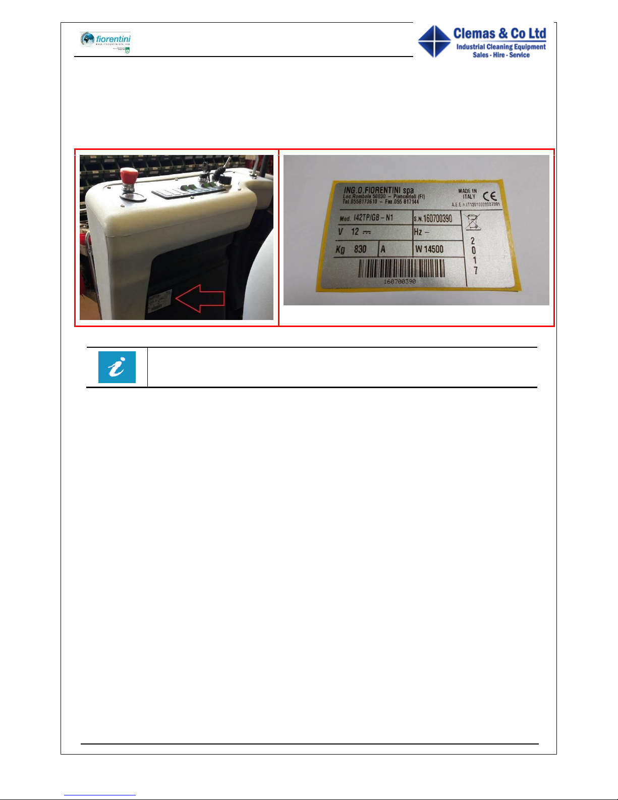
This manual suits for next models
1
Table of contents
Other FIORENTINI Scrubber manuals

FIORENTINI
FIORENTINI L14 Installation and maintenance instructions

FIORENTINI
FIORENTINI TERMINATOR-1000 User manual

FIORENTINI
FIORENTINI JOLLY 13 User manual

FIORENTINI
FIORENTINI I 42/60 GAS User manual

FIORENTINI
FIORENTINI SCOIATTOLO 75 User manual

FIORENTINI
FIORENTINI ECOMINI 430 Specification sheet

FIORENTINI
FIORENTINI ET 65-75 User manual

FIORENTINI
FIORENTINI PINKY 26 Operating instructions

FIORENTINI
FIORENTINI ECOPRO40 User manual

FIORENTINI
FIORENTINI L14 Installation and maintenance instructions