fiorini SET PLUS 2.0 - 25 User manual

MODULO PER LA PREPARAZIONE ISTANTANEA
DI ACQUA CALDA SANITARIA
ON-DEMAND DOMESTIC
HOT WATER PREPARATION UNIT
SET 2.0
SET 2.0
Taglie: 60-70-80-100-120-200
SET PLUS 2.0
Taglie: 25-35-40
Lingua/ Language
IT-EN
Cod. - Part n. 826050753
Rev. - Rev. 5
Data - Date 11/2016
MANUALE D’USO E MANUTENZIONE
USE AND MAINTENANCE MANUAL
Istruzioni originali in lingua italiana - English translation of the original instructions in Italian

2
SET PLUS 2.0 - SET 2.0
INDICE
Simbologia...........................................................................3
Osservazioni........................................................................4
Descrizione e scopo del prodotto ........................................5
Modello e tipo..................................................................5
Marcatura CE ..................................................................6
Conformità alle Direttive Europee........................................6
Identicazione......................................................................6
Pericoli e precauzioni ..........................................................7
Dati tecnici...........................................................................8
Dimensioni e caratteristiche tecniche..............................8
Descrizione componenti e attacchi per l’installazione...10
Schema d’installazione in abbinamento a
termoaccumulo..................................................................12
Installazione ed Uso ..........................................................16
Imballaggio del prodotto ...............................................16
Movimentazione del prodotto ........................................16
Luogo d’installazione.....................................................17
Fissaggio a parete
(solo per SET PLUS 2.0 - 25/35/40) .............................18
Smontaggio/montaggio dei pannelli di rivestimento......19
Installazione ..................................................................20
Collegamento elettrico ..................................................21
Messa in servizio...........................................................22
Centralina ..........................................................................23
Display della centralina .................................................23
Programmazione della centralina..................................25
Manutenzione....................................................................28
Manutenzione del modulo SET .....................................28
Pulizia periodica scambiatore
(solo da personale addetto) ..........................................29
Manutenzione della centralina ......................................31
Smaltimento.......................................................................31
Eventuali anomalie e possibili rimedi.................................32
Allegato 1: .........................................................................34
Schema elettrico SET PLUS 2.0 - 25/35/40..................34
Allegato 2: .........................................................................36
Schema elettrico SET PLUS 2.0 LFWC - 25/35/40.......36
Allegato 3: .........................................................................38
Schema elettrico SET 2.0 - 60/70/80/100/120/200 ......38
Schema elettrico quadro di potenza..................................40
CONTENTS
Symbols...............................................................................3
General warnings ................................................................4
Product description and intended use .................................5
Model and type................................................................5
CE-marking .....................................................................6
Compliance with EU Directives ...........................................6
Identication ........................................................................6
Hazards and warnings.........................................................7
Technical data......................................................................8
Dimensions and specications........................................8
Description of components and ttings for installation ..10
Installation diagram when coupled to a
hot water storage tank.......................................................12
Installation and Use...........................................................16
Packaging .....................................................................16
Handling the product .....................................................16
Installation site...............................................................17
Wall-mounting
(only for SET PLUS 2.0 - 25/35/40) ..............................18
Removing/assembling the protection panels ................19
Installation .....................................................................20
Electrical connection .....................................................21
Putting into service........................................................22
Controller...........................................................................23
Controller display ..........................................................23
Programming the controller...........................................25
Maintenance......................................................................28
Maintenance of the SET module...................................28
Heat exchanger periodic cleaning
(only authorized staff)....................................................29
Maintenance of the controller........................................31
Disposal.............................................................................31
Troubleshooting.................................................................33
Annex 1: ...........................................................................35
SET PLUS 2.0 - 25/35/40 wiring diagram ..................... 35
Annex 2: ...........................................................................37
SET PLUS 2.0 LFWC - 25/35/40 wiring diagram .......... 37
Annex 3: ...........................................................................39
SET 2.0 - 60/70/80/100/120/200 wiring diagram...........39
Power board wiring diagram..............................................40
3
SET PLUS 2.0 - SET 2.0
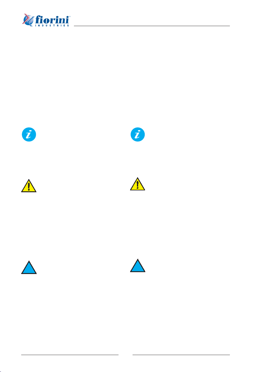
Simbologia
All’interno di questa pubblicazione possono
essere utilizzati i seguenti simboli:
PERICOLO: Richiama l’attenzione
su azioni che, se non correttamente
eseguite, possono provocare gravi
lesioni.
DIVIETO: Richiama l’attenzione su
azioni che impongono un divieto.
PERICOLO TENSIONE: Richiama
l’attenzione su azioni che, se non
correttamente eseguite, possono
provocare gravi lesioni o la morte
alle persone esposte.
PERICOLO ALTE TEMPERATURE:
Richiama l’attenzione su azioni
che, se non correttamente eseguite,
possono provocare gravi lesioni
alle persone a causa dell’alta
temperatura dei componenti.
IMPORTANTE: Richiama
l’attenzione su informazioni
tecniche o consigli pratici che
rendono possibile un utilizzo
più efcace ed economico
dell’apparecchiatura.
OBBLIGO: Richiama l’attenzione
su azioni che impongono un
obbligo al ne di ottenere il corretto
funzionamento della macchina.
Symbols
Inside this manual, the following symbols are
used:
DANGER: Warning relevant to
operations which may cause
serious injury if they are not
performed properly.
DO NOT: Indicates forbidden
actions.
DANGER ELECTRICAL VOLTAGE:
Warning relevant to certain actions
which may cause serious or mortal
injury to the exposed persons if
they are not performed properly.
DANGER HIGH TEMPERATURES:
Warning relevant to certain actions
which may cause serious injuries
due to the high temperature
of components, if they are not
performed properly.
IMPORTANT: Emphasises
technical information or practical
recommendations for a more
effective and efcient use of the
unit.
ATTENTION: Indicates actions
which are compulsory for the
machine to function properly.

4
SET PLUS 2.0 - SET 2.0
Osservazioni
Conservare il manuale in luogo asciutto, per
evitarne il deterioramento, per almeno 10
anni, per eventuali riferimenti futuri.
Leggere attentamente e completamente tutte
le informazioni contenute in questo manuale.
Prestare particolarmente attenzione alle
norme d’uso accompagnate dal simbolo
“PERICOLO” o “DIVIETO” in quanto, se
non osservate, possono causare danno alla
macchina e/o a persone e cose.
Per anomalie non contemplate in questo
manuale, interpellare tempestivamente il
Servizio Assistenza.
Il costruttore declina ogni responsabilità per
qualsiasi danno dovuto ad un uso improprio
della macchina, ad una lettura parziale o
superciale delle informazioni contenute in
questo manuale.
L’apparecchio deve essere installato in
maniera tale da rendere possibili operazioni
di manutenzione e/o riparazione.
La garanzia dell’apparecchio non copre in
ogni caso i costi dovuti ad autoscale, ponteggi
o altri sistemi di elevazione che si rendessero
necessari per effettuare gli interventi in
garanzia.
Le informazioni contenute nel presente
documento possono essere modicate senza
preavviso e non comportano l’assunzione,
nemmeno implicita, di alcun obbligo da parte
del costruttore.
È fatto divieto di riprodurre e/o rendere
nota, a terzi e a società concorrenti, tale
documentazione.
Questo manuale d’uso è parte integrante
del prodotto e lo dovrà accompagnare
sempre. In caso di smarrimento o illeggibilità
della targhetta o di questo manuale d’uso
richiedere un duplicato al costruttore.
General warnings
Keep the manual in a dry place, to avoid
deterioration, for at least 10 years for future
reference.
Read all the information contained in this
manual carefully and thoroughly.
Pay particular attention to the instructions
accompanied by the symbol “DANGER” or
“DO NOT” as failure to do so could damage
the unit and/or property or injure persons.
For any problems that are not covered in this
manual, contact your nearest Service Centre
in good time.
The manufacturer declines all responsibility
for any damage caused by the improper use
of the machine, and the partial or supercial
reading of the information contained in this
manual.
The unit must be installed so that maintenance
and/or repairs can be carried out.
In any case, the guarantee on the unit does not
cover the costs of aerial ladders, scaffolding
or other hoist systems which may be required
for interventions under guarantee.
Theinformationcontainedinthisdocumentation
can be modied without prior notice, with no
obligation for the manufacturer.
Any reproduction and/or disclosure to third
parties and competitors of said documentation
is strictly forbidden.
This manual is an integral part of the product
and must always accompany the same. If the
product’s identication plate or this manual
goes lost, ask to the manufactor for a copy
of it.

5
SET PLUS 2.0 - SET 2.0
Descrizione e scopo del prodotto
Il modulo è un sistema completo “plug and
play” ed è stato progettato per l’installazione
in impianti civili o industriali per la produzione
di acqua calda per usi igienico-sanitari.
Il modulo, da collegare ad un termoaccumulo
da cui preleva energia, è completo di tutti i
componenti necessari al suo funzionamento
(scambiatore a piastre, pompa di circolazione
ecc.) e, attraverso una centralina con
display graco, permette all’utente di
tenere monitorato il suo funzionamento e di
impostarne facilmente i parametri di utilizzo.
Lo scambio termico avviene mediante
scambiatore a piastre in acciaio inox AISI
316 con la massima garanzia di igiene e
prestazioni.
Modello e tipo
Modulo per la preparazione istantanea di
acqua calda sanitaria pensile:
qSET PLUS 2.0 - 25
qSET PLUS 2.0 - 35
qSET PLUS 2.0 - 40
Modulo per la preparazione istantanea
di acqua calda sanitaria con struttura
autoportante:
qSET 2.0 - 60
qSET 2.0 - 70
qSET 2.0 - 80
qSET 2.0 - 100
qSET 2.0 - 120
qSET 2.0 - 200
Contrassegnare con una X (
q
) la
casella interessata controllando i
dati nella targhetta di identicazione.
Product description and intended use
The preparation unit is a comprehensive “plug
and play” system designed for installation
in residential or industrial plants for the
production of domestic hot water.
The unit has to be connected to a hot water
storage tank from which it gets power. It is
tted with all necessary components (plate
exchanger, recirculating pump, etc.) for
operation. User can monitor the unit operation
and easily set its operating parameters by
means of a controller with graphical display.
Heat exchange is made by an AISI 316
stainless steel plate-type heat exchanger,
ensuring maximum hygiene and performance.
Model and type
Wall-mounted unit for on-demand domestic
hot water preparation:
qSET PLUS 2.0 - 25
qSET PLUS 2.0 - 35
qSET PLUS 2.0 - 40
Unit for on-demand domestic hot water
preparation with self-supporting structure:
qSET 2.0 - 60
qSET 2.0 - 70
qSET 2.0 - 80
qSET 2.0 - 100
qSET 2.0 - 120
qSET 2.0 - 200
Mark with an X (
q
) the most
appropriate box using the data plate
as a reference.

6
SET PLUS 2.0 - SET 2.0
Marcatura CE
Il prodotto, conforme alle speciche direttive
dell’Unione Europea, reca la marcatura CE.
Conformità alle Direttive Europee
Direttiva Titolo
2006/42/CE Direttiva macchine.
2014/30/EU Direttiva Compatibilità
Elettromagnetica.
2014/35/EU Direttiva Bassa Tensione.
2014/68/EU PED, Direttiva in materia di
attrezzature a pressione.
Identicazione
Il prodotto è identicato dalla targhetta
applicata su di esso.
CE-marking
The product complies with the relevant EU
directives and carries the CE marking.
Compliance with EU Directives
Directive Title
2006/42/EC Machinery Directive
2014/30/UE Electromagnetic Compatibility
directive
2014/35/UE Low Voltage Directive
2014/68/UE PED, Pressure Equipment
Directive.
Identication
The unit is identied by the special data plate
applied on the same.
Modello
Type
842030003X
SET 40 -PREPARATORE ISTANTANEO ACS #
Matricola
Serial number
0
01
/1
Codice
Code
842030003X
MADE IN ITALY
Mese di costruzione
Month of costruction
05/2010
Peso in funzionamento (kg)
Operating weight (kg)
-
Peso di trasporto (kg)
Shipping weight (kg)
24
Capacità accumulo (l)
Tank capacity (l)
-
Capacità vaso di espans.(l)
Expansion tank capacity (l)
-
Precarica vaso di espans.(bar)
Expansion tank pre-loading press.(bar)
-
Pressione maxdi esercizio (bar)
Maximum operating pressure (bar)
6
Pressione di collaudo (bar)
Pressure test (bar)
9
Valvola di sicurezza (bar)
Safety valve set(bar)
-
N° e tipo pompa/e
N° and model of pump/s
SXM 32-50
Min - Max
Temperatura (°C)
Temperature (°C)
Gruppo Fluido
Fluid Group
-95 2 - LIQUIDO
Codice manuale
Manual code
826050158
ALIMENTAZIONE ELETTRICA - ELECTRICAL SUPPLY
Voltaggio
Voltage
230V-50Hz
8088888 676878
0.205 1
F.L.I. kW F.L.A. A
Schema elettrico
Wiring diagram
825040050
47122 Forlì - Italy
www.fiorinigroup.it
7
SET PLUS 2.0 - SET 2.0
Pericoli e precauzioni
Ricordiamo che l’utilizzo di prodotti che
impiegano energia elettrica ed acqua,
comporta l’osservanza di alcune regole
fondamentali quali:
• è consentito l’uso dell’apparecchio
esclusivamente con acqua sanitaria;
• è vietato utilizzare l’apparecchio con
pressioni e temperature dei uidi maggiori
di quelle massime ammesse;
• è vietato eseguire qualsiasi intervento o
operazione di manutenzione sul prodotto
senza aver portato il recipiente a pressione
atmosferica;
• è vietato eseguire qualsiasi intervento o
operazione di manutenzione sul prodotto
senza aver vericato le temperature del
uido, del recipiente e senza essersi
adeguatamente protetti dal calore.
• è vietato toccare l’apparecchio se si è a
piedi nudi e con parti del corpo bagnate
o umide;
• è vietato salire sulla parte superiore del
modulo.
• è vietato eseguire qualsiasi intervento o
operazione di manutenzione sul prodotto
prima di aver scollegato l’apparecchio
dalla rete di alimentazione elettrica;
• è vietato modicare i dispositivi di
sicurezza;
• è vietato disperdere, abbandonare
o lasciare alla portata dei bambini il
materiale d’imballo (cartone, graffe,
sacchetti di plastica, ecc.) in quanto può
essere potenziale fonte di pericolo.
• è vietato l’uso del prodotto ai bambini.
Disconnettere il modulo
dall’impianto prima di effettuare
saldature su qualunque punto
dell’impianto di cui il SET fa parte.
Hazards and warnings
For the use of units using electricity and water,
some fundamental rules must be obeyed:
• The appliance must only be used with
domestic water.
• Do not use the appliance if the uid
pressure and temperature are beyond the
envisaged ones.
• Do no carry out any repair or maintenance
interventions on the appliance if the vessel
is not at atmospheric pressure.
• Do no carry out any repair or maintenance
interventions before checking the
temperatures of both uid and vessel and
wearing a personal protective equipment
to protect yourself from heat.
• Do not touch the appliance with bare feet
or wet hands or other parts of your body.
• Do not climb on the unit.
• Do no carry out any repair or maintenance
interventions before disconnecting the
appliance from the mains.
• Do not tamper with the safety devices.
• Do not release the packaging material
(cardboard, clips, plastic bags, etc.) to the
environment and do not leave it within the
reach of children as it is a potential source
of hazard.
• Keep the product out of the reach of
children.
Disconnect the unit from the
system before carrying out welds
on any part of the system the SET
is incorporated into.
8
SET PLUS 2.0 - SET 2.0
Dati tecnici
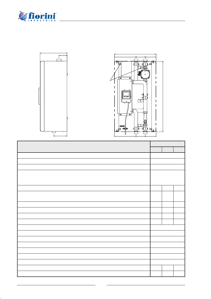
Dimensioni e caratteristiche tecniche
Modelli SET PLUS 2.0 - 25/35/40
Technical data
Dimensions and specications
Models SET PLUS 2.0 - 25/35/40
Dati tecnici - Technical data SET PLUS 2.0
25 35 40
Alimentazione elettrica - Power supply 230V / 50 hz / 1 ph
Potenza pompa elettrica min/max (W) - Primary circuit pump power min/max (W) 2 / 52
Assorbimento pompa primario min/max (A) - Primary circuit pump absorption min/max (A) 0.04 / 0.52
Potenza massima pompa di ricircolo impianto gestibile dalla centralina, pompa non fornita
(W) - Plant’s recirculating pump max power to be managed from the controller, pump is not
supplied (W)
185
Portata primario (litri/h) - Primary circuit ow rate (l/h) 2000 2800 2800
Prevalenza residua circuito primario (m.c.a.)
Primary circuit residual head (mWc) 2.0 1.0 1.0
Peso senza imballo (kg) - Weight without packing (kg) 15 16 16
Peso con imballo (kg) - Weight with packing (kg) 22 24 24
Volume circuito primario (l) - Primary circuit volume (l) 1.1 1.6 1.6
Volume circuito sanitario (l) - DHW circuit volume (l) 0.85 1.4 1.4
Pressione massima di esercizio (bar) - Max working pressure (bar) 6
Connessioni circuito primario - Primary circuit connections 1” GAS M
Connessioni circuito secondario - Secondary circuit connections 1” GAS M
Temperatura massima di utilizzo (°C) - Max operating temperature (°C) 95
Grado di protezione elettrico - Degree of protection IP40
Tipo spina collegamento elettrico - Electrical connection plug type Schuko 10-16A/250V
Lunghezza cavo elettrico (m) - Electrical cable length (m) 1.5
Portata minima di accensione (l/min) - Start-up min. ow rate (l/min) 2 2 5
Portata massima a.c.s. (l/min) - Max DHW ow rate (l/min) 40 40 100
690
406
80
270
130 90 105
211 90 105
Fori per ssaggio a
parete
Holes for
wall-mounting
9
SET PLUS 2.0 - SET 2.0
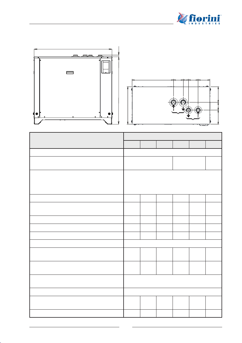
Modelli SET 2.0 - 60/70/80/100/120/200
Dati tecnici - Technical data SET 2.0
60 70 80 100 120 200
Alimentazione elettrica - Power supply 230V / 50 hz / 1 ph
Potenza elettrica/assorbimento pompa primario
Primary circuit pump power/absorption 310 W - 1.37 A 450 W - 2.01 A 600 W
- 2.7 A
Potenza massima pompa di ricircolo impianto gestibile
dalla centralina (pompa non fornita)
Plant’s recirculating pump max power to be managed
from the controller (pump is not supplied)
185 W
Portata primario (litri/h) - Primary circuit ow rate (l/h) 6700 8200 9000 11000 14000 22000
Prevalenza residua circuito primario (m.c.a.)
Primary circuit residual head (mWc) 2.0 4.0 2.0 2.0 4.0 2.0
Peso a vuoto (kg) - Tare weight (kg) 130 130 140 150 150 290
Volume circuito primario (l) - Primary circuit volume (l) 1.79 2.08 2.22 2.65 3.22 6.55
Volume circuito sanitario (l) - DHW circuit volume (l) 1.93 2.22 2.36 2.79 3.36 6.37
Pressione massima di esercizio - Max working pressure 6 bar
Connessioni circuito primario
Primary circuit connections (I°) 1”1/2 F 1”1/2 F 1”1/2 F 1”1/2 F 1”1/2 F 2”1/2 F
Connessioni circuito secondario
Secondary circuit connections (II°) 1”1/4 F 1”1/4 F 1”1/4 F 1”1/4 F 1”1/4 F 2” F
Temperatura massima di utilizzo
Max operating temperature 95 °C
Grado di protezione elettrico - Degree of protection IP40
Portata minima di accensione (l/min)
Start-up min. ow rate (l/min) 5 5 10 10 10 20
Portata massima a.c.s. (l/min) - Max DHW ow rate (l/min) 100 100 200 200 200 400
1005
534125
I°
II°
68 125153
22
871
202
484
100182
Vista dall’alto - View from above
Models SET 2.0 - 60/70/80/100/120/200
10
SET PLUS 2.0 - SET 2.0
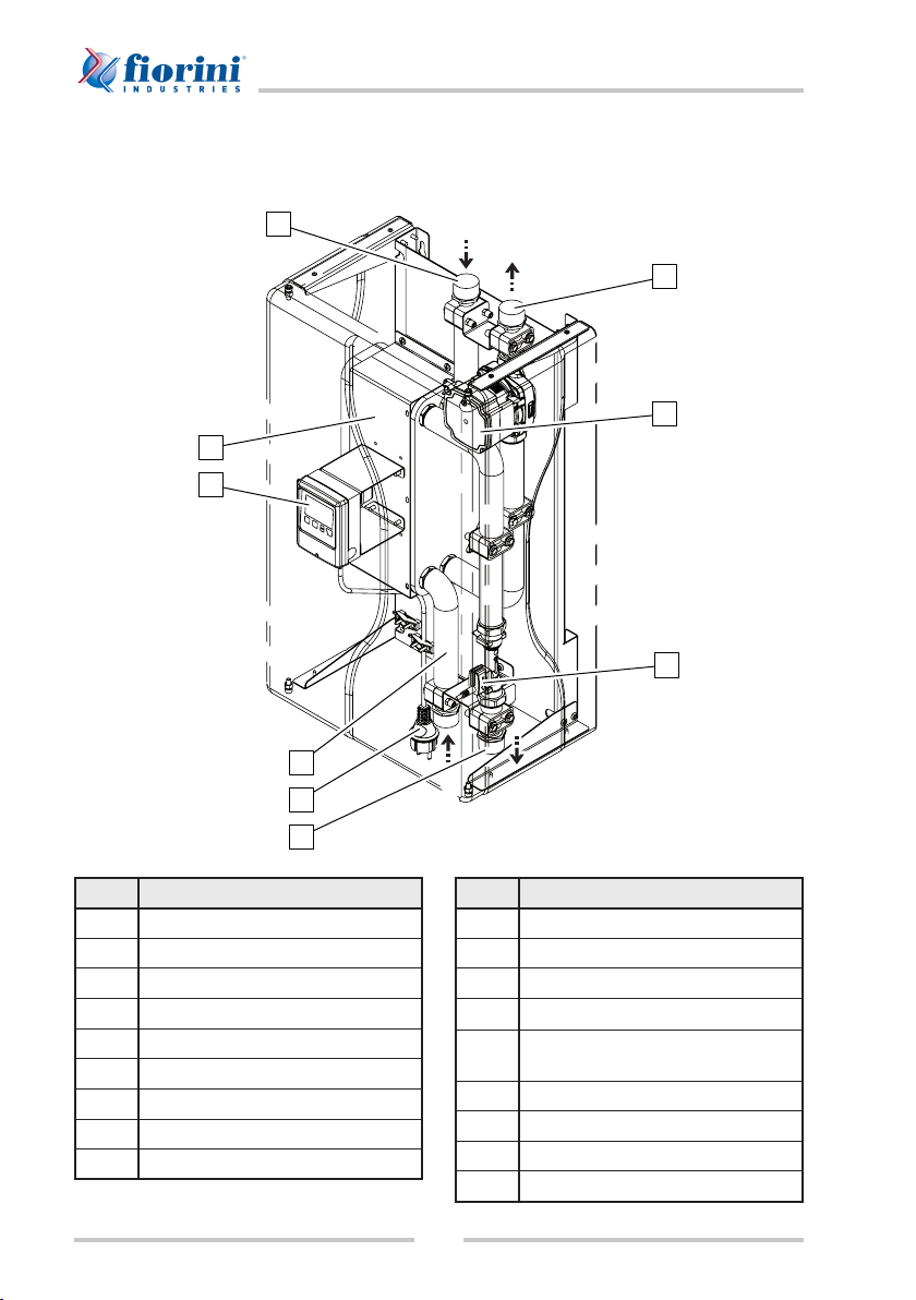
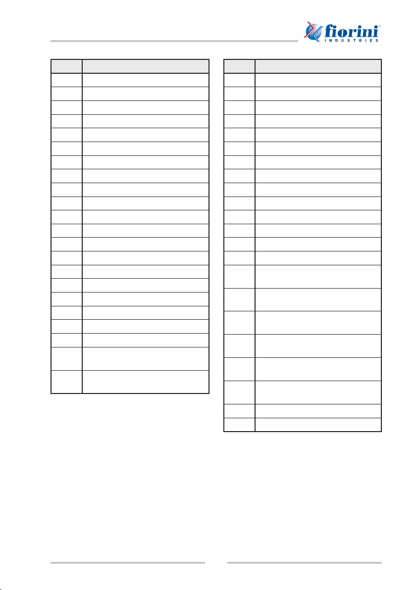
Descrizione componenti e attacchi per
l’installazione
Modelli SET PLUS 2.0 - 25/35/40
Pos. Descrizione
APompa circuito primario
BFlussimetro
CCentralina di regolazione
DIngresso acqua rete
EScambiatore a piastre inox AISI 316
FIngresso primario
GUscita primario
HUscita a.c.s.
ISpina Schuko pompa
Description of components and ttings for
installation
Models SET PLUS 2.0 - 25/35/40
Pos. Description
APrimary circuit pump
BFlow meter
CAdjustment controller
DWater inlet
EAISI 316 stainless steel plate-type
heat exchanger
FPrimary inlet
GPrimary outlet
HDHW outlet
IPump Schuko plug
C
E
F
A
B
G
I
H
D

11
SET PLUS 2.0 - SET 2.0
F
G
IH
L
C
B
D
A
E
Modelli SET 2.0 - 60/70/80/100/120/200
Pos. Descrizione
APompa elettronica circuito
primario
BSonda di temperatura PT1000
CCentralina di regolazione
DQuadro elettrico di potenza
EScambiatore a piastre inox AISI 316
FIngresso primario
GUscita primario
HIngresso a.c.s. rete
IUscita a.c.s.
LFlussimetro
Models SET 2.0 - 60/70/80/100/120/200
Pos. Description
APrimary circuit electronic pump
BTemperature probe PT1000
CAdjustment controller
DPower electric board
EAISI 316 stainless steel plate-type
heat exchanger
FPrimary inlet
GPrimary outlet
HDHW inlet
IDHW outlet
LFlow meter

12
SET PLUS 2.0 - SET 2.0
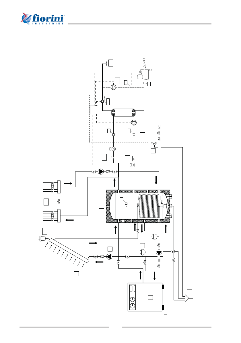
Schema d’installazione in abbina-
mento a termoaccumulo
Modelli SET PLUS 2.0 - 25/35/40
7
1
8
3
2
6
5
9
4
VFS
14
13
12
11
10
S1
S2
14
13
V1
Limite fornitura gruppo SET
SET unit delivery limit
SCARICO
OUTLET
FILTRO
FILTER
ACQUEDOTTO
WATER MAINS
Installation diagram when coupled to
a hot water storage tank
Models SET PLUS 2.0 - 25/35/40

13
SET PLUS 2.0 - SET 2.0
Pos. Descrizione
1Pompa di calore o fonte primaria
2Vaso d’espansione chiuso
3Pompa
4Valvola di sicurezza
5Pannello solare
6Valvola di sato
7Scarico
8Utenze
9Termoaccumulo Puffer
10 Preparatore a.c.s. SET
11 Utenza
12 Pompa anello ricircolo sanitario
13 Rubinetti per lavaggio circuito
sanitario
14
Rubinetti per l’isolamento
dell’impianto sanitario durante il
lavaggio
S1 Sonda temperatura ricircolo
(opzionale)
S2 Sonda temperatura accumulo
(opzionale)
VFS Sensore combinato di temperatura
e portata
Pos. Description
1Heat pump or primary source
2Closed expansion tank
3Pump
4Safety valve
5Solar cell
6Relief valve
7Outlet
8Utilities
9Puffer hot water storage
10 SET domestic hot water unit
11 Utility
12 DHW recirculating pump
13 DHW circuit cleaning connection
14 Valve for closing domestic hot
water circuit during washing
S1 Circulation temperature probe
(optional)
S2 Water storage temperature probe
(optional)
S5 Combined temperature and ow
probe
14
SET PLUS 2.0 - SET 2.0
Modelli SET 2.0 - 60/70/80/100/120/200
7
1
8
3
2
6
5
9
4
11
14
10
12
13
VFS
S1
S4
S6
S2
S3
S5
Limite fornitura gruppo SET
SET unit delivery limit
SCARICO
OUTLET
FILTRO
FILTER
ACQUEDOTTO
WATER MAINS
Models SET 2.0 - 60/70/80/100/120/200
15
SET PLUS 2.0 - SET 2.0
Pos. Descrizione
1Pompa di calore o fonte primaria
2Vaso d’espansione chiuso
3Pompa
4Valvola di sicurezza
5Pannello solare
6Valvola di sato
7Scarico
8Utenze
9Termoaccumulo Puffer
10 Preparatore a.c.s. SET
11 Pompa anello ricircolo sanitario
12 Miscelatrice motorizzata 3 punti
13 Valvola deviatrice 3 vie
14 Utenza
S1 Ricircolo (opzionale)
S2 Acqua fredda (opzionale)
S3 Primario (opzionale)
S4 Accumulo alto (opzionale)
S5 Accumulo medio (opzionale)
S6 Ritorno primario (opzionale)
V1 Segnale pompa primario 0-10V/
PWM
VFS Sensore combinato di temperatura
e portata
Pos. Description
1Heat pump or primary source
2Closed expansion tank
3Pump
4Safety valve
5Solar cell
6Relief valve
7Outlet
8Utilities
9Puffer hot water storage
10 SET domestic hot water unit
11 DHW recirculating pump
12 Powered 3-point mixing valve
13 3-way bypass valve
14 Utility
S1 Circulation temperature probe
(optional)
S2 Cold water temperature probe
(optional)
S3 Primary ow temperature probe
(optional)
S4 Storage top temperature probe
(optional)
S5 Storage middle temperature
probe (optional)
S6 Primary return ow temperature
probe (optional)
V1 0-10V/PWM signal primary pump
VFS Warm water tap
16
SET PLUS 2.0 - SET 2.0
Installazione ed Uso
Imballaggio del prodotto
Il prodotto viene spedito imballato in casse di
legno o ssato su pallet in legno.
Nel caso sia consegnato imballato in casse
di legno occorre aprire la cassa dal lato
superiore e, se necessario, dai lati; rimuovere
i dispositivi di ssaggio quindi togliere il
prodotto dalla cassa.
Nel caso sia consegnato su pallet occorre
togliere la copertura di polipropilene che
protegge il prodotto, rimuovere i dispositivi
che lo ssano quindi toglierlo dal pallet.
Occorre smaltire sempre gli
imballi nei modi e nei tempi
consentiti dalle vigenti normative.
Il legno può essere bruciato
mentre il polipropilene non deve
essere nè bruciato nè disperso
nell’ambiente.
Legno e chiodi potrebbero
provocare serie ferite; usare guanti
di protezione individuale.
Movimentazione del prodotto
Il prodotto deve essere tolto dall’imballo e
movimentato esclusivamente con carrello
elevatore a forche.
Il prodotto è sprovvisto di punti di aggancio
per il sollevamento. Non sollevare il prodotto
con gru o altri dispositivi di sollevamento
provvisti di imbragature.
Durante la movimentazione
del prodotto occorre prestare
attenzione a non danneggiarlo.
Installation and Use
Packaging
The product is delivered inside a wooden box
or xed to a wooden pallet.
If the product is delivered inside a wooden
box, open the box top rst and then the two
sides, if necessary. Cut any ties and remove
the product.
If the product is delivered on a pallet, remove
the polypropylene protective cover, cut any
ties and remove the product from the pallet.
Dispose of any packaging materials
as envisaged by any local and
national regulations in force. Wood
can be burned; polypropylene must
neither be burned nor released to
the environment.
Wood and nails may injure you.
Use protective gloves.
Handling the product
The unit shall be unpacked and handled with
a forklift truck only.
The unit has no lifting points. Do not lift it using
a crane or other hoisting equipment equipped
with slinging accessories.
Be very careful when handling the
unit to avoid damaging the same.

17
SET PLUS 2.0 - SET 2.0
Luogo d’installazione
Il prodotto deve essere installato all’interno di
un edicio e deve essere posizionato tenendo
conto degli spazi necessari all’esecuzione
delle operazioni di manutenzione (vedi tabella
e disegno).
Misure spazi liberi per manovra
A1000 mm
B1000 mm
C500 mm
D100 mm
Se si è scelto un modello pensile (SET PLUS
2.0 - 25/35/40): vericare che la parete su cui
sarà installato il prodotto sia perfettamente
verticale e capace di sostenere il peso del
prodotto stesso e del suo contenuto (vedi
targhetta caratteristiche tecniche). Per il
montaggio seguire le istruzioni descritte al
par. “Fissaggio a parete”.
Se si è scelto un modello con struttura auto-
portante (SET 2.0 - 60/70/80/100/120/200):
vericare che la supercie su cui sarà installa-
to il prodotto sia piana e capace di sostenere
il peso del prodotto stesso e del suo conte-
nuto (vedi targhetta caratteristiche tecniche).
Prima di procedere con
l’installazione si consiglia di
rimuovere i pannelli di rivestimento
per agevolare le operazioni
descritte ai paragra successivi
ed evitare di danneggiarli (vedi
par. “Smontaggio/montaggio dei
pannelli di rivestimento”).
Installation site
Position the unit inside a building leaving a
sufcient space all around for maintenance
(see table and drawing).
Free spaces to leave all around the unit
A1000 mm
B1000 mm
C500 mm
D100 mm
If you have a wall-mounted model (SET
PLUS 2.0 - 25/35/40), ensure that the wall
where the product shall be installed is vertical
and has a sufcient load-bearing capacity for
the product and its content (see data plate).
For the installation, obey the instructions
provided in paragraph “Wall mounting”.
If you have a model with self-supporting
structure (SET 2.0 - 60/70/80/100/120/200),
ensure that the oor on which the product
shall be installed, is at and has a sufcient
load-bearing capacity for the product and its
content (see data plate).
Prior to proceeding with the
installation, we recommend
removing the protection panels
as explained in par. “Removing/
assembling the protection panels”
to avoid damaging them during
assembly.
B
A
C
C
DD
SET 2.0
60/70/80/100/120/200
SET PLUS
2.0 - 25/40
A
18
SET PLUS 2.0 - SET 2.0
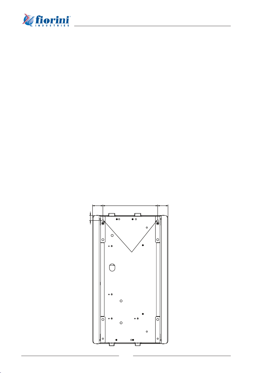
Fissaggio a parete (solo per SET PLUS 2.0
- 25/35/40)
Dopo essersi assicurati che la parete sia
capace di sostenere il peso del prodotto
stesso e del suo contenuto, procedere come
segue:
• posizionare e ssare la dima sulla parete
nel punto prescelto. Con l’ausilio di una
livella a bolla d’aria vericare che i due
fori indicati sulla dima siano perfettamente
orizzontali;
• marcare sulla parete i due punti di sostegno
del modulo.
• realizzare i due fori sulla parete;
• inserire i tasselli (forniti in dotazione) nei
fori appena effettuati;
• posizionare il SET e ssarlo alla parete.
27
(56)56 295
Fori per ssaggio
a parete
Holes for
wall-mounting
Vista posteriore - Rear view
Wall-mounting (only for SET PLUS 2.0 -
25/35/40)
Ensure that the wall has a sufcient load-
bearing capacity, then:
• position the template on the wall in the
chosen site and x it. Using a spirit level,
ensure that the two holes on the template
are perfectly horizontal;
• trace two supporting points on the wall;
• drill the wall;
• insert the anchor bolts (supplied) into the
drilled holes;
• position the SET unit and x it to the wall.

19
SET PLUS 2.0 - SET 2.0
Smontaggio/montaggio dei pannelli di
rivestimento
Nel caso sia necessario rimuovere uno dei
pannelli del modulo è necessario:
• allentare le viti laterali (A) del pannello che
si desidera rimuovere;
• svitare e togliere le viti (B) poste nella
parte inferiore del pannello;
• slare il pannello.
Per rimontare il pannello eseguire la
procedura inversa.
Questa procedura è valida
per i modelli SET 2.0 -
60/70/80/100/120/200, in quanto
il pannello frontale dei modelli
SET PLUS 2.0 - 25/35/40 è ssato
tramite calamite.
A
A
A
B
A
B
Removing/assembling the protection
panels
In order to remove a protection panel of the
unit, obey the following instructions:
• loosen the lateral screws (A) of the panel
to be removed;
• unscrew and drive out screws (B) located
at the bottom of the panel;
• pull off the panel.
For the assembly, follow the procedure above
in reverse order.
This procedure only
applies to models SET 2.0 -
60/70/80/100/120/200, as the front
panel of models in SET PLUS
2.0 - 25/35/40 is held in place by
magnets.

20
SET PLUS 2.0 - SET 2.0
Installazione
• Installare il prodotto nel luogo prescelto
seguendo le indicazioni fornite nel
paragrafo “Luogo d’installazione”).
• Eseguire i collegamenti alle tubazioni
di mandata e ritorno (vedi “Descrizione
componenti e attacchi per l’installazione”)
in modo tale che questi:
- non gravino con il loro peso sul prodotto
stesso;
- consentano l’accesso e lo smontaggio
degli eventuali accessori.
• È consigliato montare una valvola di
intercettazione su ogni tubazione di
mandata e ritorno del circuito primario per
facilitare le operazioni di manutenzione.
• È obbligatorio montare una valvola di
intercettazione su ogni tubazione di
mandata e ritorno del circuito sanitario per
consentire il lavaggio dell’impianto.
• Assicurarsi che l’impianto sia dotato di
una valvola di sicurezza e di un vaso
ad espansione conforme alla Direttiva
2014/68/UE, aventi caratteristiche
adeguate.
• Effettuare l’allacciamento elettrico come
descritto al paragrafo “Collegamento
elettrico”.
• Far effettuare la programmazione della
centralina da un tecnico specializzato.
• Portare l’interruttore generale posto sul
quadro elettrico del modulo in posizione
ON.
• Installare sul circuito sanitario un ltro a
monte del modulo.
• Si consiglia l’installazione di una valvola
termostatica per le utenze nali, al ne di
scongiurare il pericolo di scottature (ad es.
durante shock termico anti-legionella).
Installation
• Install the product in the chosen site
following the instructions provided in
paragraph “Installation site”).
• Make the connections to the delivery
and return pipes (see “Description of
components and ttings for installation”)
so:
- their weight doesn’t bear on the
product;
- you can gain access and dismantle any
parts of the unit.
• It is advisable to t an on-off valve to each
delivery and return line of the primary
circuit for ease of maintenance.
• It is mandatory to t an on-off valve to each
delivery and return line of the domestic
water circuit to clean the system.
• Ensure that the system is tted with
appropriae safety valve and expansion
tank in compliance with Directive 2014/68/
EU.
• Proceed with the electrical connection
as explained in paragraph “Electrical
connection”.
• Have the controller programmed by a
qualied technician.
• Turn on the main switch on the unit’s
electric board
• On the domestic water circuit, t a lter
upstream of the unit.
• It is also advisable to install a thermostatic
valve for nal users so as to avoid any
scalding hazard due, for instance, to a
thermal shock during the antilegionella
cycle.
This manual suits for next models
8
Table of contents


