manuals.online logo
Brands
  1. Home
  2. •
  3. Brands
  4. •
  5. Seitron
  6. •
  7. Measuring Instrument
  8. •
  9. Seitron PRESSOTEST 200 User manual

Seitron PRESSOTEST 200 User manual















POR MDX BI0 0SE 021338A0 171012
> 0 <
SET
UNIT FUNC
ESC
MEM PRINT
RQTVCDNG
KPUVTWOGPVU
35(6627(67 F



3257$%/(',*,7$/0$120(7(5

x
For UNI 7129 and UNI 11137: 2012 gas tightness tests
x
Features gas tightness test printout
x
Pressure recorder function (Data Logger)
x
Programmable min/max alarm levels
x
Auditory and visual display alerts for off-range values
x
Manual set for main parameters
x
Automatic switch off function
x
Operates on 6 1.5V alkaline AAA batteries
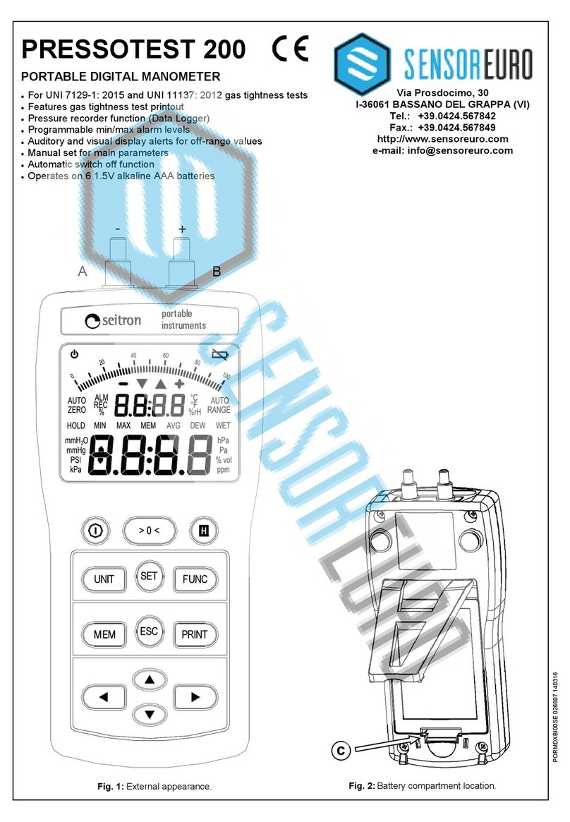
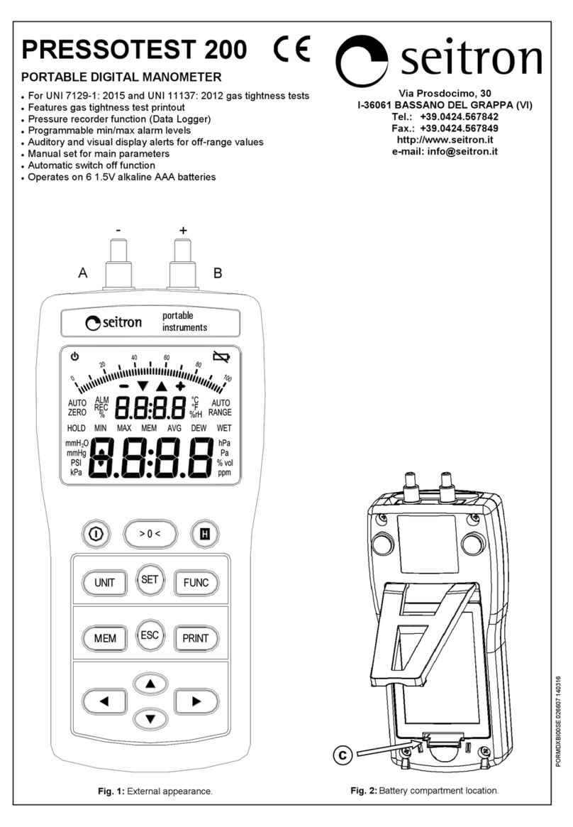
)LJ Battery compartment location.
9LD3URVGRFLPR
,%$66$12'(/*5$33$9,
7HO 
)D[ 
KWWSZZZVHLWURQLW
HPDLOLQIR#VHLWURQLW

)LJ External appearance.
F
-+
AB














2
POR MDX BI0 0SE 021338A0 171012
29(59,(:
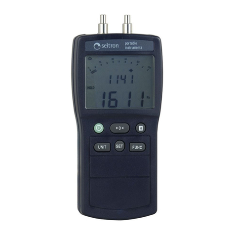
The PRESSOTEST is a portable digital manometer which has been designed for hydraulic systems.
As well as all the standard manometer functions, PRESSOTEST also features a digital auto-zero function, hold
function, six different measurement units, overflow and underflow alarms, minimum and peak alarms with
programmable thresholds, date and time display clock, programmable automatic switch off function.
PRESSOTEST’s distinguishing characteristic is that it carries out UNI 7129 (new systems) and
UNI 11137: 2012 (existing systems) gas tight tests and prints out the results on an infrared ray printer. It also
features a Data Logger which records and prints instantaneous, minimum, mean and peak values at
programmable time intervals.
PRESSOTEST has very low energy consumption levels and is powered by six 1.5V AAA batteries.

7(&+1,&$/63(&,),&$7,216
Supply : 9V, 6x1,5V AAA alkaline batteries
Input: 10 mA
Measuring range: ± 130 hPa
Measurement units: Pa, hPa, kPa, PSI, mmHg, mmH2O
Accuracy : ±1% readout value P > 15 hPa
±0.1 hPa -15 hPa < P < 15 hPa
±1.5% readout value P < -15 hPa
Including linearity, repeatibility and hysteresis
Resolution: According to the unit and measuring range:
Sensor type: semiconductor
Overload: 750 hPa
Display: 2 x LCD 4 digits + sign.
Protection level: IP30
Operating temperature: 0°C .. +40°C
Storage temperature: -10°C .. +50°C
Humidity: 20% .. 80% RH non condensing
Auto switch off: Programmable from 1 to 30 mins
Case: Material: ABS V0 self-extinguishing
Colour: Dark blue Pantone 5534
Size: 87 x 162 x 41mm (L x A x P)
Weight: ~ 264 gr.

67$5783

3UHOLPLQDU\RSHUDWLRQV
Before use please take the following steps:
x
Insert batteries (included) in the battery housing unit ensuring correct polarity. To remove battery housing
protection panel press gently downwards on the plastic lever (c in fig. 2).
x
Connect silicon tubes (supplied) to the instrument's input (b in fig. 1) and output (a in fig. 1).

%DWWHU\FKHFNDQGUHSODFHPHQW
If battery tension goes below the 6.5V threshold the low battery icon ' ' will appear in the display's top
righthand corner. To replace batteries follow the instructions in the paragraph above.
Unit Interval Resolution
Pa ±9999 1
hPa
±99.99 0.01
elsewhere 0.1
kPa ±9.999 0.001
elsewhere 0.01
PSI ±1.885 0.001
mmHg ±9.999 0.008
elsewhere 0.01
mmH2O ±999.9 0.1
elsewhere 1














3
POR MDX BI0 0SE 021338A0 171012
23(5$7,21

.H\ERDUGGHVFULSWLRQ



































6ZLWFKLQJRQRII
To switch PRESSOTEST on or off press the ’ ’ key for at least 2 seconds.
0HDVXUHPHQWXQLW
The ’ 81,7 ’ key edits the pressure measurement unit. All the most common measurement units are available:
3D, K3D, N3D, 36,, PP+J, PP+

2. The set measurement unit will remain valid after the instrument has been
switched off.

$XWR]HUR
The ’ !   ’ key activates the autozero procedure. During autozero the instrument samples the input pressure
and sets it as the zero reference for the following measurements. During this procedure the display will read
’ DXWR]HUR ’ and the numbers in the lower display will flash.

+ROG
The ’ + ’ key activates the ’ +2/' ’ mode that ’ freezes ’ the pressure measured at that moment. At the same
time the upper display will continue to show the pressure reading at input. Each time the ’ +’ key is pressed
the pressure reading shown in the upper display will be transferred to the lower display and shown as a fixed
value. The hold mode is not available in the Functions menu.

6HOHFW(GLW
Use the horizontal arrow keys ’ ’ to move around the menu, scroll the list of functions, select the
configuration parameters and display gas tight test results and Data Logger.
Use the vertical arrow keys ’ ’ to edit parameters. Pressed once they activate the edit function (the
selected parameter will flash), further pressure will change the values. Numeric values can be altered when
flashing by pressing the horizontal arrow keys and, when available, decimal figures can be set by pressing the
horizontal arrow keys again to place the decimal point where required. To exit the edit mode confirm the
parameters by pressing ’ 6(7’ or return to previous parameters by pressing ’ (6& ’.
$XWR]HUR
0HDVXUHPHQWXQLW 
&RQILUP
0HQXFRQILJXUDWLRQ0HPRU\
6ZLWFKRQRII +2/'0RGH
&DQFHO
)XQFWLRQVPHQX
3ULQWPHQX
6HOHFW
(GLW
> 0 <
SET
UNIT FUNC
ESC
MEM PRINT














4
POR MDX BI0 0SE 021338A0 171012
&RQILUP&DQFHO
The ’ 6(7 ’ key confirms operations. It must be pressed each time a function is activated or to confirm a
parameter.
The ’ (6& ’ key cancels current operations. This key can be used to interrupt a gas tight test or to reset the
previous parameters.

&RQILJXUDWLRQPHQX0HPRU\PHQX
The ’ 0(0 ’ key accesses the memory where the configuration parameters and the results from the functions
in the Func menu are stored. Access to either of these areas depends on the active menu.
To access configuration parameters press the ’ 0(0 ’ key on the pressure measurement screen (main
screen), which is accessed by pressing ’ (6& ’ several times. To access function results press the ’ 0(0 ’ key
on the function selection screen which is accessed from the pressure measurement screen by pressing the ’
)81& ’ key and the arrow keys. In both cases visualise values using the horizontal arrow keys once the
memory area has been accessed.
Instrument configuration parameters are described below:

’ EX==’ Activates the auditory alerts (buzzer).

’ WRII ’ Activates automatic switch off (time off). PRESSOTEST will switch off automatically after the time
set by the last key pressure. Set from 1.. 30 minutes or Off. Approaching switch off is signalled by
5 beeps at one second intervals. The ’ R’ icon in the top lefthand corner of the display shows that
the automatic switch off function is activated. This function is temporarily suspended during g a s
tight tests and Data Logging.
’ $6X3 ’ Activates the peak alarm.
’ /6X3 ’ Sets the peak alarm threshold. The alarm is triggered when pressure exceeds the set threshold.
The threshold can be set between -9999 and +9999, and may include numbers with decimal
points. The threshold is associated to a measurement unit that can be edited using the ’81,7’
key.
’ $,Q)’ Activates the minimum alarm.
’ /,Q) ’ Sets the minimum alarm threshold. The alarm is triggered when the pressure falls below the set
threshold. The threshold can be set between -9999 and +9999, and may include numbers with
decimal points. The threshold is associated to a measurement unit that can be edited using the
’81,7’ key.

’ 3RXW’ Sets printout speed:
6ORZ: the instrument waits until the printer has printed each line before sending the data for the
next line.
 )DVW: all the data is sent to the printer.
'DWH Sets the clock date ’\HDU’
GD\PRQWK
7LPH Sets the clock time ’ VHFRQGV’
KRXUPLQXWHV


3ULQWIXQFWLRQ
To print align the black panel on the right of the instrument with the printer sensor and press the ’ 35,17 ’ key.
This function can be activated from both the pressure measurement screen, where either the current pressure
measurement or the blocked value in Hold can be printed, and the gas tight test results display and Data
Logger screens, for printouts for the systems owners.














5
POR MDX BI0 0SE 021338A0 171012
)XQFWLRQVPHQX
Use the ’ )81& ’ key to access functions. Use the arrow keys to select a gas tight test or the Data Logger
function from the menu:

81,Gas tight test for working systems.
81, Gas tight test for new or reconditioned systems.
'DWD/RJJHU Acquires and saves pressure trends.
81,*DVWLJKWWHVWIRUH[LVWLQJV\VWHPV 

The UNI 11137: 2012 norm applies to internal systems which are already functioning. To carry out UNI 11137:
2012 gas tight tests with PRESSOTEST input the required parameters for the test (system volume, the gas
type the system runs on, the test gas), adjust the system to the test pressure specified by the instrument,
stabilise the test gas and then wait for one minute for Methane and LPG in air and 2.5 minutes for the LPG fuel
while the manometer evaluates the fall in pressure in the system. From the pressure fall figure and the system
characteristics the instrument calculates the extent of the leak and compares it to the range required by the
norm to generate the result of the test.
Start the UNI 11137: 2012 gas tight test by pressing ’ 6(7 ’ on the 81,function selection screen.
Step by step the instrument requests the operator to insert the parameters detailed below and confirm them
with ’ 6(7 ’. Other details are supplied in the flow diagrams illustrated further on in the manual.
’ XRO’ The system volume is a required parameter for carrying out the UNI 11137: 2012 gas tight test.
With PRESSOTEST it can either be inserted, if known, or measured by a simple procedure. Given
the large number of small systems, the instrument also has a third option for systems of up to
18 dm3(litres); here no specific volume is required because the instrument automatically considers
a volume of 18 dm3.
The first option displayed for setting the gas tight test parameters is the option for systems of up to
18 dm3, shown on the display by ’ -18L ’ (volume of less than 18 litres). This selection can be
confirmed by using ’ 6(7 ’ or the system volume can be input using the horizontal arrow keys.
For manual input the instrument automatically displays the volume used for the last gas tight test
carried out. This value can be edited by using the arrow keys as described in the Select/edit
paragraph on page 3.
On the insert volume screen it is also possible to calculate the volume directly using the syringe
supplied with the pipe kit for gas tight tests. The procedure is summarised in a few simple steps
below:
x
Connect the syringe to its pipe from the gas tight test kit (opposite the pump).
x
Open the tap and extract exactly 100 ml (100 cc) of gas from the plant
x
Wait until the system restabilises. Removing the syringe full of gas disturbs the system’s
pressure and the manometer displays its variability by a flashing volume indication. Wait until it
has stopped flashing before continuing.
x
Inject the contents of the syringe back into the system and close the pipe kit tap.
x
Wait until the system restabilises again. As before the volume indicator will flash until it has
stabilised. Wait until it stops flashing.
x
As soon as the system restabilises and the display stops flashing the measured volume will be
shown.
To carry out the test with the volume shown, whether it has been input or measured, press ’ 6(7 ’.
’ &RPE’ System combustible gas.
Gas tight tests are carried out under different test conditions and according to the type of gas the
system uses. Select combustible gas from the options: natural gas ’ *Q$W’ and LPG. ’ *3/’.
’ J$’Test gas.
Gas tight testing is carried out under different conditions according to the test gas used. Select the
test gas from either the system’s combustible gas ’ &RPE ’ or air ’ $ULD ’.
’ W$E’Stabilisation time.
Set the test gas stabilisation time when added to the system.














6
POR MDX BI0 0SE 021338A0 171012
An important point to bear in mind with regards the sequence of settings for a gas tight test is that the values
inserted are saved and retrieved for carrying out the test only if the test itself is started.
This stores the test data until a new test is carried out, but has the disadvantage that if a screen is cancelled by
pressing ’ (6& ’ it goes back to the beginning of the whole sequence and causes the loss of the data
previously recorded.
7DEOH ([DPSOHV UHODWLQJ WR WKH YDULRXV OHQJWKV RI LQGRRU V\VWHPV FDSDFLW\ DSSUR[LPDWHO\
FRUUHVSRQGLQJ WR GP

 GHSHQGLQJ RQ WKH PDWHULDO DQG WKH GLDPHWHU RI WKH IXHO JDV
DGGXFWLRQSLSH
1RWH:KHQ WKH PHDVXUHPHQW JURXS FDQ QRW EH H[FOXGHG IURP WKH WHVW WKH LQGLFDWLYH OHQJWK RI WKH
SODQWLVJLYHQLQEUDFNHWV.
The system priming screen is visualised after the test parameters have been recorded.
The upper display shows the message ’ 3RP3 ’, indicating the operator should start pumping gas, alternating
with the pressure to reach. The lower display reads off the system pressure.
The test must be carried out using the positive pressure connection: if a negative pressure value is detected
during pressurisation the display will visualise an error message ’ (UU ’ to show the wrong connection is being
used.
Test pressures must be as close as possible to the specific reference conditions shown in the table ’ Reference
standard pressures ’ depending on the system’s combustible gas and the test gas used.
Because it is virtually impossible to accurately meet these conditions, the instrument evaluates the ’T PLV’
leakage amount in the measurement conditions, then adjusts this value in order to calculate the ’ TULI’ amount
according to the reference conditions. In order to evaluate the piping safety conditions the correct parameter
that must be taken into account is the leakage amount in the reference conditions ’ TULI ’.
7DEOH5HIHUHQFHSUHVVXUHV
The values indicated do not have to be precisely observed. For test purposes it is sufficient that the system is
close to those required.

After the system has been primed the test gas stabilisation phase is started by pressing ’ 6(7 ’. The display
visualises the pressure measured in the system and the residual stabilisation time. The stabilisation phase is
automatically terminated when the time set has expired or can be interrupted by pressing the ’ 6(7 ’ key.
After stabilisation the actual gas tight test is run by evaluating the fall in the system’s pressure over a 1 minute
interval for Methane and LPG in air and 2.5 minutes for the LPG fuel.
6WHHO &RSSHU0XOWLOD\HU3RO\HWK\OHQH
'LDPHWHU OHQJWKP ,QWHUQDOGLDPHWHUPP OHQJWKP
1/2" 82 (68) 10 228 (190)
3/4" 49 (40) 12 160 (133)
1" 28 (23) 14 116 (97)
1 1/4" 17 (14) 16 90 (75)
19 64 (53)
25 37 (31)
26 34 (28)
34 20 (17)
&RPEXVWLEOHJDV 7HVWJDV 3UHVVXUH >3D@
*Q$W
(Methane) combustible gas 2200
air 5000
*3/
(LPG) combustible gas 3000
air 5000














7
POR MDX BI0 0SE 021338A0 171012
During the test the display visualises the pressure and the test time remaining. Pressing the ’ 0(0 ’ key will
show the fall in pressure from the beginning of the test.
Running the test automatically saves the parameters involved and deletes data from previous tests. The
flashing ’ 5(& ’ icon shows the data is being recorded.
At the end of the test the results are displayed automatically:
W(6W ’
L’ Positive test result. The system is approved to run (leak flow  GP3
/h for methane and
GP3/h for LPG). 
’ **’ Limited positive test result. The system is approved for a maximum of 30 days running (leak
flow 1< .. GP3/h) for methane and 0,4< .. GP3/h) for LPG).
’ 1R’ Negative test result. The system is not approved to run (leak flow >5 dm3
/h for methane and
>2 dm3/h for LPG).
’
(UU’ Non valid test result.
&RPE System combustible gas.
J$Test gas used.
XRO System volume in dm3.
3System pressure at start of test.
3System pressure at end of test.
G3P1 - P2 pressure difference. When pressure is falling d3is negative.
T0LV: Leakage amount in the measurement conditions (in dm3/h).
TULI Leakage amount adjusted according to reference conditions (in dm3/h).
 Date of test.
 Time test run started.
Test results can be printed on a printer with infrared ray linkup by pressing the ’ 35,17 ’ key. During printout a
screen with the description ’ 3RXW ’ and the message ’ $WW ’ is visualised. This screen is automatically exited on
completion. The printout function is not available during test runs.
Test results are retained in the memory even after the instrument has been switched off, until a new test run
overwrites them.
Saved parameters can be retrieved by pressing ’ 0HP ’ in the ’ 81,   ’ test selection screen and
can be visualised and printed like those just run.














8
POR MDX BI0 0SE 021338A0 171012
81,*DVWLJKWWHVWVIRUQHZRUUHFRQGLWLRQHGV\VWHPV 

The UNI 7129 norm test is required to approve new systems or reconditioned systems that have been unused
for a period of maintenance. For the UNI 7129 gas tight test with PRESSOTEST prime the system to a
pressure of at least 100mBar with inert gas, stabilise the test gas for at least 15 minutes and then wait
15 minutes while the instrument evaluates the fall in pressure in the system. The system is considered gas
tight if the pressure fall is less than 10 Pa.
Select the 81,  norm and press ’ 6(7 ’ to start the test, select the time interval for the test gas
stabilisation phase from a range of 15 .. 99 minutes.
Once the time interval for the stabilisation of the test gas has been set the system priming screen is displayed.
The upper display shows the message ’ 3RP3 ’, indicating the operator should start pumping gas, alternating
with the pressure to reach. The lower display reads off the system pressure.
The test must be carried out using the positive pressure connection: if a negative pressure value is detected
during pressurisation the display will visualise an error message ’ (UU ’ to show the wrong connection is being
used.
After the system has been primed the test gas stabilisation phase is started by pressing ’ 6(7 ’. The display
visualises the pressure measured in the system and the residual stabilisation time. The stabilisation phase is
automatically terminated when the time set has expired or can be interrupted by pressing the ’ 6(7 ’ key.
After stabilisation the actual gas tight test is run. The UNI 7129 requires the evaluation of the fall in pressure in
the system over a 15 minute interval. During the test the display visualises the pressure and the test time
remaining. Pressing the ’ 0(0 ’ key will show the fall in pressure from the beginning of the test.
Running the test automatically saves the parameters involved and deletes data from previous tests. The
flashing ’ 5(& ’ icon shows the data is being recorded.
At the end of the test the results are displayed automatically:
W(6W ’
L’ Positive test result. The system is gas tight.
’ 1R’ Negative test result. The system leaks.
’
(UU’ Non valid test result.
3System pressure at start of test.
3System pressure at end of test.
G33 - 3 pressure difference. When pressure is falling d3is negative.

 Date of test.
 Time test run started.
Test results can be printed on a printer with infrared ray linkup by pressing the ’ 35,17 ’ key. During printout a
screen with the description ’ 3RXW ’ and the message ’ $WW ’ is visualised. This screen is automatically exited on
completion. The printout function is not available during test runs.
Test results are retained in the memory even after the instrument has been switched off, until a new test run
overwrites them.
Saved parameters can be retrieved by pressing ’ 0HP ’ in the ’ 81,  ’ test selection screen and can be
visualised and printed like those just run.




















9
POR MDX BI0 0SE 021338A0 171012
'DWDOR'DWDORJJHUIXQFWLRQ 

The ’ 'DWD /RJJHU ’ function records and saves pressare status over time. Analysed instantaneous, minimum,
mean and peak value sizes and coupled with their observation instants can be evaluated.
Select the function, before activating recording using ’ 6(7 ’, some parameters need to be set:
’WUHF’total recording time in minutes.
Total recording time in minutes is required. Select from a range of 1 to 9999 minutes.
’ QUHF’number of samples.
Select from 2 to 60.

At the end of the configuration sequence the recorder start up screen is visualised with the message
 G/R2Q . Activate recording by pressing ’ 6(7 ’, this also deletes any previous recorded data. The ’ 5(& ’
icon flashes during recording.

When recording starts measured pressure is displayed. Pressing the ’0(0’ key accesses data record
memory and pressure values, each coupled with its observation instant. At the end of the sequence the
minimum, peak and mean size values are recorded (different to the sample minimum, peak and mean values).
All information is available in real time and can be displayed in the following order:
First sample, 01 istant.
Last sample, ’ QU(F’ instant. Untaken samples are shown as ’  ’.
0,1 Pressure minimum. The observation instant is that of the last pressure sample taken before the
reading.
0$; Pressure peak. The observation instant is that of the last pressure sample taken before the reading
$9* Mean pressure, evaluated by accumulating values with a 1 sec interval. The associated observation
instant is that of the last pressure sample taken.
W5(& Recording time in minutes.
Q5(& Number of samples taken.
 Recording start date.
Data from the Data Logger can be printed on infrared ray printers by pressing ’35,17 ’.
During printout a screen with the description ’ 3RXW ’ and the message ’ $WW ’ is visualised. This screen is
automatically exited on completion. The printout function is not available during recording.
Records are retained in the memory even after the instrument has been switched off, until a new test
overwrites them.
Saved data can be retrieved by pressing ’ 0HP ’ in the test selection screen characterised by the message
’ 'DWDOR’, and can be visualised and printed like those just run.














10
POR MDX BI0 0SE 021338A0 171012
81,*DVWLJKWWHVWH[LVWLQJV\VWHPV
)ORZFKDUWIXQFWLRQVPHQX 

3URFHGXUHIRULQVHUWLQJSDUDPHWHUV
- Press key or to activate the edit mode (parameter flashes).
- Press or to edit.
- If the parameter is numeric press or to edit the flashing figure.
- If numbers with decimal points are in the consented range press or to place the
decimal point in the position required.
- Press ’ 6(7 ’ to confirm or ’ (6& ’ to cancel.
Select test for systems up
to 18 dm3or insert the
system volume in dm3.
On the volume data
insertion screen volume
measurement can be
carried out as described on
page 5.
Insert the combustible gas
used for the system:
GnAt - GPL
(Natural gas - LPG.).
Press ’ )XQF ’ to select
UNI 11137: 2012 gas tight
8QL

8oL
/
&omb
JnAt
8oL

Press ’ 6HW ’ to start gas
tight test, or press
’ 0(0’ to retrieve previous
test results.
tHVt
Vi

J2C

ESC














11
POR MDX BI0 0SE 021338A0 171012
PRINT
Pressurizze
the piping
REC dP

J2C

6t$b

Automatically
tHVt
Vi
Sout
Dtt
Automatically
REC



J2C





J2C





J2C

3om3

J2C

Insert test gas stabilisation
time in minutes.
Prime the system to the
pressure shown on the
upper display.
Start the test gas
stabilisation. Press
’ 6HW ’ to stop stabilisation
before allotted time expires.
Wait to run gas tight test.
Press ’ 0(0 ’ to display
system pressure or
pressure change at the start
of the test.
Align printer with the
manometer and press
’ 35,17 ’ to print test
results.
After printing press ’ (6& ’
to return to pressure
measurements.
At the end of the test the
result is displayed
automatically. Use or
to visualise test details.
Insert the test gas: air or
combustible.
*DV
DriD














12
POR MDX BI0 0SE 021338A0 171012

J2C

8QL

Press ’ )XQF ’ twice to
select UNI 7129 gas tight
test.
Press ’ 6HW ’ to start the
gas tight test, or press ’
0(0’ to retrieve previous
test results.
Insert test gas stabilisation
time in minutes.
Prime the system to the
pressure shown on the
upper display.
6t$b

3om3

J2C




J2C

tHVt
Vi
[

ESC
81,  *DV WLJKW WHVW IRU QHZ RU UHFRQGLWLRQHG
)ORZFKDUWIXQFWLRQVPHQX 

3URFHGXUHIRULQVHUWLQJSDUDPHWHUV
- Press key or to activate the edit mode (parameter flashes).
- Press or to edit.
- If the parameter is numeric press or to edit the flashing figure.
- If numbers with decimal points are in the consented range press or to place the
decimal point in the position required.
- Press ’ 6(7 ’ to confirm or ’ (6& ’ to cancel.
Pressurizze
the piping














13
POR MDX BI0 0SE 021338A0 171012
PRINT
tHVt
Vi
Sout
Dtt
At the end of the test the
result is displayed
automatically. Use or
to visualise test details.
Start the test gas
stabilisation.
Press ’ 6HW ’ to stop
stabilisation before allotted
time expires.
Wait to run gas tight test.
Press ’ 0(0 ’ to display
system pressure or
pressure change at the
start of the test.
REC dP

J2C

Automatically
Automatically
REC



J2C





J2C

Align printer with the
manometer and press
’ 35,17 ’ to print test
results. After printing press
’ (6& ’ to return to pressure
measurements.














14
POR MDX BI0 0SE 021338A0 171012

J2C

dDtD
/o
trHc

nrHc

Press ’ )XQF ’ three times
to select the data logger
function.
Press ’ 6HW ’ to start data
logger, or press ’ 0(0’ to
retrieve the results of the
previous test.
Insert recording time in
minutes.
Insert the number of
samples.
'DWD/RJJHU)XQFWLRQ
[





J2C


ESC
)ORZFKDUWIXQFWLRQVPHQX 

3URFHGXUHIRULQVHUWLQJSDUDPHWHUV
- Press key or to activate the edit mode (parameter flashes).
- Press or to edit.
- If the parameter is numeric press or to edit the flashing figure.
- If numbers with decimal points are in the consented range press or to place the
decimal point in the position required.
- Press ’ 6(7 ’ to confirm or ’ (6& ’ to cancel.














15
POR MDX BI0 0SE 021338A0 171012




J2C

5(&





J2C


PRINT
Automatically
Sout
Dtt
Start recording by pressing
’ 6HW ’.
Press ’ 0(0 ’ to visualise
system pressure or
recorded values.
At the end of recording
acquired data is displayed.
Use or .
To visualise details.
dOo
Rn




J2C

5(&

Align printer with the
manometer and press
’ 35,17 ’ to print test
results.
After printing press ’ (6& ’
to return to pressure
measurements.














16
POR MDX BI0 0SE 021338A0 171012
EW
2P
3DUDPHWHUFRQILJXUDWLRQH[DPSOH
Set automatic switch off
time from 1 .. 30 minutes or
disable function using off.
Activate peak alarm.
Press ’ 0(0 ’ to access the
parameter configuration
menu.
EW
RII
VQII

VQII
2))
Activate ’ buzzer ’.

J2C

ESC
$6u3
RII

$6u3
RP

ESC
ESC
)ORZFKDUWIXQFWLRQVPHQX 

3URFHGXUHIRULQVHUWLQJSDUDPHWHUV
- Press key or to activate the edit mode (parameter flashes).
- Press or to edit.
- If the parameter is numeric press or to edit the flashing figure.
- If numbers with decimal points are in the consented range press or to place the
decimal point in the position required.
- Press ’ 6(7 ’ to confirm or ’ (6& ’ to cancel.














17
POR MDX BI0 0SE 021338A0 171012


$LnI
RP

$LnI
RII





Set minimum alarm
threshold (the alarm goes
off if the pressure falls
below the threshold).
Decimal values are allowed.
The ’ 81,7 ’ key edits the
threshold measurement
unit.
Set printout speed.
Set peak alarm threshold
(the alarm goes off if the
pressure exceeds the
threshold). Decimal values
are allowed. The ’ 81,7 ’
key edits the threshold
measurement unit.
Set minimum alarm.
/6u3

J2C

$LnI

J2C
$LnI


J2C


SQWV
)$67
SQWV
VORX
Adjust clock date.
Adjust clock time.
/6u3


J2C


ESC
ESC
ESC
ESC
ESC


ESC














18
POR MDX BI0 0SE 021338A0 171012
35(6685(0($685(0(17

The manometer has two pressure connections which can be used to measure:
3UHVVXUHPHDVXUHPHQWV: apply pressure to be measured to the positive (righthand) connection and leave the
other connection open.
9DFXXP PHDVXUHPHQWV: apply pressure to be measured to the negative (lefthand) connection and leave the
other connection open.
'LIIHUHQWLDO SUHVVXUH PHDVXUHPHQWV: use both connections and visualise the pressure difference between
the positive (righthand) connection and the negative (lefthand) connection. For pressure peak readings apply
greater pressure to the positive connection.
$&&(6625,(66833/,('

PRESSOTEST comes complete with the following accessories:
Rauclair pipe, internal ø 4mm, length 30cm, with 9mm ø female
pipe fitting.
Silicon pipe internal ø 4mm, length 90cm.
Silicon pipe internal ø 7mm, length 15cm.
Brass pipe 4 x 5mm, length 16cm.
&$/,%5$7,21
Our manometers leave the factory complete with a test certificate to show they have passed their final test and
correspond to their declared precision performance as measured against a test sample instrument calibrated to
international standards. Calibration certificates are available on request showing single calibration values.
The manufacturer advises recalibration every 12 months under normal operational conditions.
Within the parameters of ongoing product development the manufacturer reserves the right to alter technical data and performance without prior warning. Consumers
are guaranteed against product conformity defects under European directive 1999/44/
F
and under the manufacturer’s own warranty. Sales points can supply the
complete text of the warranty on request.














19
POR MDX BI0 0SE 021338A0 171012















20
POR MDX BI0 0SE 021338A0 171012
























































 



9LD3URVGRFLPR,%$66$12'(/*5$33$9,,7$/<7HO)D[
KWWSZZZVHLWURQLWHPDLOLQIR#VHLWURQLW
6S$


Other manuals for PRESSOTEST 200

2

Other Seitron Measuring Instrument manuals

Seitron CHEMIST 500 User manual

Seitron

Seitron CHEMIST 500 User manual

Seitron CHEMIST 600 User manual

Seitron

Seitron CHEMIST 600 User manual

Seitron PRESSOTEST 100 User manual

Seitron

Seitron PRESSOTEST 100 User manual

Seitron CHEMIST 200 User manual

Seitron

Seitron CHEMIST 200 User manual

Seitron PRESSOTEST 300 User manual

Seitron

Seitron PRESSOTEST 300 User manual

Seitron BE COOL M4 User manual

Seitron

Seitron BE COOL M4 User manual

Seitron CHEMIST 900 RACK User manual

Seitron

Seitron CHEMIST 900 RACK User manual

Seitron BE COOL V1 SMART User manual

Seitron

Seitron BE COOL V1 SMART User manual

Seitron PRESSOTEST 200 User manual

Seitron

Seitron PRESSOTEST 200 User manual

Seitron CHEMIST 100 BE GREEN User manual

Seitron

Seitron CHEMIST 100 BE GREEN User manual

Seitron CHEMIST 900 RACK User guide

Seitron

Seitron CHEMIST 900 RACK User guide

Seitron PORVAL0112 Instruction Manual

Seitron

Seitron PORVAL0112 Instruction Manual

Seitron NOVO User guide

Seitron

Seitron NOVO User guide

Seitron GAS T ONE User guide

Seitron

Seitron GAS T ONE User guide

Seitron N-VO User manual

Seitron

Seitron N-VO User manual

Seitron S1500 User guide

Seitron

Seitron S1500 User guide

Seitron NOVO User guide

Seitron

Seitron NOVO User guide

Seitron S500 User guide

Seitron

Seitron S500 User guide

Seitron PRESSOTEST 200 User manual

Seitron

Seitron PRESSOTEST 200 User manual

Seitron PRESSOTEST 300 User manual

Seitron

Seitron PRESSOTEST 300 User manual

Seitron CHEMIST 400 User manual

Seitron

Seitron CHEMIST 400 User manual

Seitron CHEMIST 600 BE GREEN User guide

Seitron

Seitron CHEMIST 600 BE GREEN User guide

Seitron CASPER User manual

Seitron

Seitron CASPER User manual

Popular Measuring Instrument manuals by other brands

SEP LEM012SD user manual

SEP

SEP LEM012SD user manual

Lovibond PM 620 instruction manual

Lovibond

Lovibond PM 620 instruction manual

Ponpe 8252 Operation manual

Ponpe

Ponpe 8252 Operation manual

FILL-RITE 806C Owner's operation & safety manual

FILL-RITE

FILL-RITE 806C Owner's operation & safety manual

Vega VEGAPULS 62 operating instructions

Vega

Vega VEGAPULS 62 operating instructions

Thermo Scientific NanoDrop OneC user guide

Thermo Scientific

Thermo Scientific NanoDrop OneC user guide

Linear Technology ANALOG DEVICES DC2608 manual

Linear Technology

Linear Technology ANALOG DEVICES DC2608 manual

Olympia EKM 2000 owner's manual

Olympia

Olympia EKM 2000 owner's manual

berlinger Fridge-tag 2 user guide

berlinger

berlinger Fridge-tag 2 user guide

HBM MC3 operating manual

HBM

HBM MC3 operating manual

Sunwin EF-200 user manual

Sunwin

Sunwin EF-200 user manual

Mobeye ThermoGuard TwinLog CML2285 user manual

Mobeye

Mobeye ThermoGuard TwinLog CML2285 user manual

Vega VEGAPULS 67 operating instructions

Vega

Vega VEGAPULS 67 operating instructions

forlong DTSY1286E user manual

forlong

forlong DTSY1286E user manual

GE Multilin DDFR instruction manual

GE

GE Multilin DDFR instruction manual

Delmhorst F-2000R Operation manual

Delmhorst

Delmhorst F-2000R Operation manual

UEi DL429B instruction manual

UEi

UEi DL429B instruction manual

Micronics U3000 user manual

Micronics

Micronics U3000 user manual

manuals.online logo
manuals.online logoBrands
  • About & Mission
  • Contact us
  • Privacy Policy
  • Terms and Conditions

Copyright 2025 Manuals.Online. All Rights Reserved.