Fire-Eye HX Series User manual

HX SERIES
HARDWARE ADMINISTRATION GUIDE
HX 4400 (REGULATORY MODEL: HX4400)
HX SERIES / 2016
F I R E E Y E T E C H N I C A L D O C U M E N T A T I O N

FireEye and the FireEye logo are registered trademarks of FireEye, Inc. in the United
States and other countries. All other trademarks are the property of their respective
owners.
FireEye assumes no responsibility for any inaccuracies in this document. FireEye
reserves the right to change, modify, transfer, or otherwise revise this publication
without notice.
Copyright © 2016 FireEye, Inc. All rights reserved.
HX 4400 Hardware Administration Guide
Revision 5
FireEye Contact Information:
Website:www.fireeye.com
Support Email:support@fireeye.com
Support Website:csportal.fireeye.com
Phone:
United States:1.877.FIREEYE (1.877.347.3393)
United Kingdom:44.203.106.4828
Other: 1.408.321.6300

CONTENTS
Preface 6
CHAPTER 1: The FireEye HX 4400 7
The Front View 7
Bezel 7
Button 8
LEDs 8
Chassis 9
The Rear View 9
Power Port 9
I/O Ports 10
Management Ports 10
CHAPTER 2: Deployment 11
HX Series Deployment 11
CHAPTER 3: Installation 13
Before You Begin 13
Site Requirements 14
Installation Site Guidelines 14
Rack Precautions 14
Server Precautions 15
Rack-Mounting Precautions 15
Ventilation Requirements 15
Cabling Requirements 15
Power Requirements 16
Rack Installation 16
Contents
©2016 FireEye 3

Installing the Inner Rails on the Appliance 16
Installing the Outer Rails on the Rack 18
Mounting the Appliance on the Rack 19
Attaching Cables to your Appliance 21
Turning On the Appliance 21
CHAPTER 4: Baseline Configuration 23
Network Information Requirements 23
Configuring the Appliance via the LCD Panel 24
LCD Panel Navigation Buttons 25
LCD Panel Menus 26
Required Ports and Protocols 28
CHAPTER 5: Replacements 31
Return Process 31
Replacing an Appliance Including Disk Drives 33
Replacing an Appliance Excluding Disk Drives 33
Backing Up and Restoring the Appliance Database 34
Backing Up and Restoring the Database Using Release 2.6 and Earlier 34
Backing Up the Appliance Configuration 34
Backing Up the Appliance Database 35
Restoring the Appliance Configuration 35
Restoring the Appliance Database 36
Backing Up and Restoring the Appliance Database Using Release 3.0 and Later 37
Backing Up the Database 37
Restoring the Appliance Database 38
Applying License Keys 40
Identifying the Failed Disk Drive 40
Removing and Replacing an HX 4400 Disk Drive 41
Removing and Replacing an HX 4400 Power Supply Unit 43
Contents
4 ©2016 FireEye

Appendices 45
Appendix 1: System Specifications 45
Appendix 2: Product Compliance Information 47
Technical Support 49
Documentation 49
Contents
©2016 FireEye 5

Preface
This guide provides an overview of the FireEye HX 4400 and describes how to install it.
This guide is intended for system administrators responsible for deploying, operating, and
maintaining FireEye products, and for security and information technology (IT) managers
and personnel interested in learning more about FireEye technologies.
HX 4400 Preface
6 ©2016 FireEye
CHAPTER 1: The FireEye HX 4400
The FireEye HX 4400 extends your ability to detect and block advanced malware to your
endpoints on or off your premises. It automates data collection amongst your ecosystem to
correlate events, providing you with better insight for the remediation and prevention of
advanced attacks.
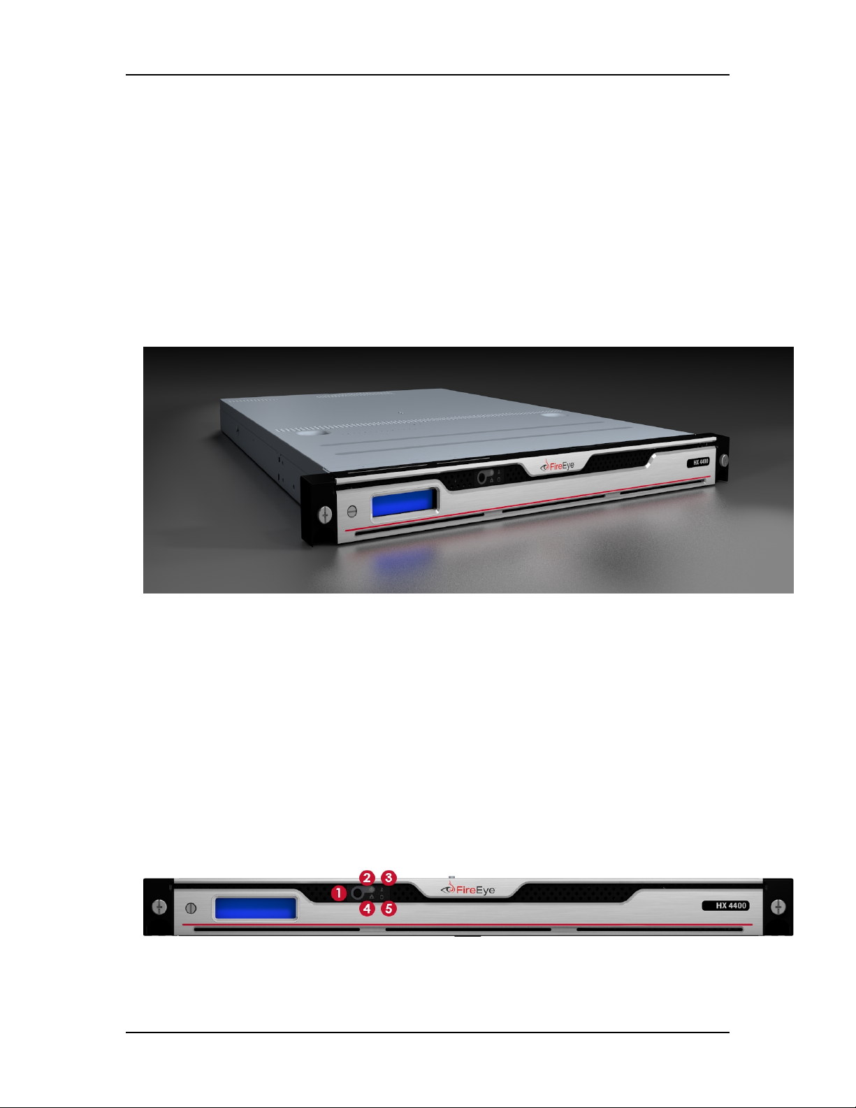
The Front View
The HX 4400 comes with a sleek removable bezel that can be removed to access the
chassis.
Bezel
©2016 FireEye 7
Hardware Administration Guide The Front View

1) Power Button 4) NIC Activity LED
2) Power LED 5) HDDLED
3) System Health Indicator LED
Button
lPower: Use the power button to turn the appliance on or off. Turning off the power
with this button removes the main power but keeps the standby power supplied to
the appliance. Therefore, unplug the appliance before servicing.
LEDs
The LEDs provide critical information about parts of the appliance. The following table
describes each LED.
LED Flashing Steady Off Normal
State
Power N/A Green and steady indicates the
appliance is receiving power
No
power is
supplied
to the
system
Green
and
steady
System
Health
Indicator
Amber and
flashing at 1 Hz
indicates a fan
failure
Amber and
flashing at 0.25
Hz indicates a
power supply
failure
Green and steady indicates proper
functioning
Amber and steady along with a
beeping buzzer indicates a power
supply, fan, or overheat failure, which
may be caused by cables obstructing
the airflow in the appliance or the
ambient room temperature being too
high
No
power is
supplied
to the
system
Green
and
steady
NIC
Activity
Flashing and
green indicates
activity via
management 1
port and or
management 2
port
N/A No
activity
or no
power is
supplied
to the
system
Green
and
steady
HX 4400 CHAPTER 1: The FireEye HX 4400
8 ©2016 FireEye
Hardware Administration Guide The Rear View
LED Flashing Steady Off Normal
State
HDD Degraded
SAS/SATA
drive
connection
Green and steady indicates normal
operation
No
power is
supplied
to the
system
Green
and
steady
Chassis
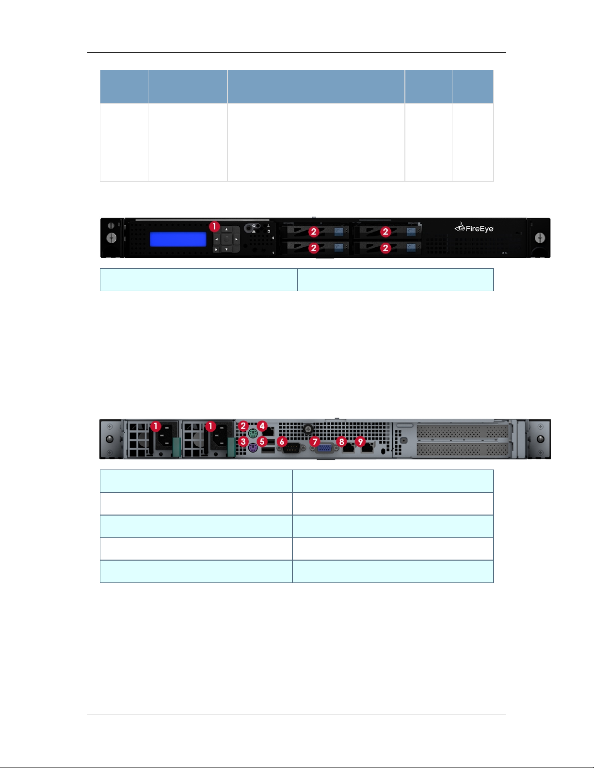
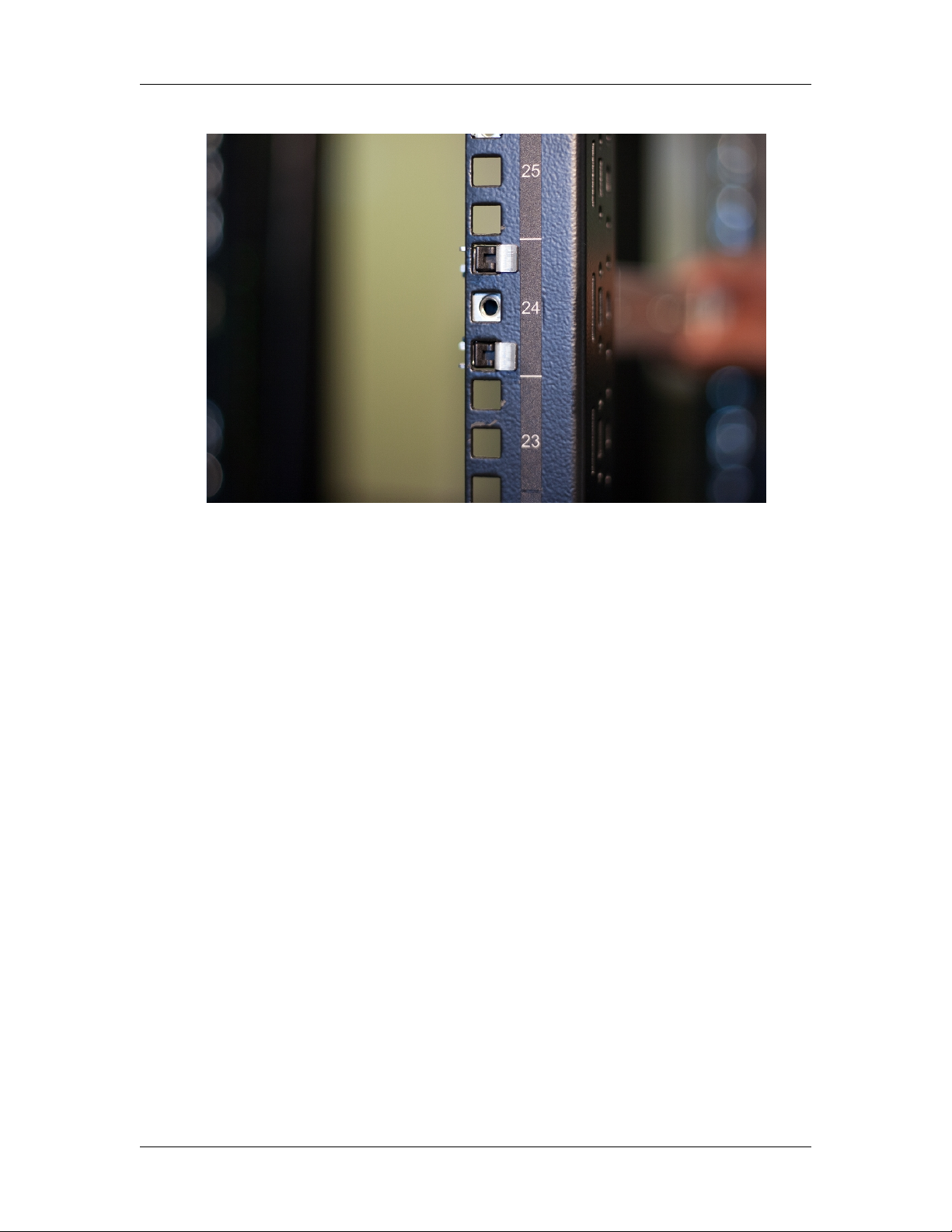
1) LCDPanel Navigation Buttons 2) DiskDrive Carrier
lLCD Panel Navigation: Use the navigation buttons to perform basic configurations
of the appliance. See Configuring the Appliance via the LCD Panel on page24 for
more information.
lDisk Drive Carrier: Each carrier can house a hot-swappable disk drive. See
Removing and Replacing an HX 4400 Disk Drive on page41 for more information.
The Rear View
1) Power Port 6) SerialConsole Port
2) PS/2 Mouse Port 7) Video Port
3) PS/2 Keyboard Port 8) ether1 (RJ45) Management 1 Port
4) IPMI/Serial over Ethernet Port 9) ether2 (RJ45) Management 2 Port
5) USB Ports
Power Port
lPower: Connect your power source to this port to provide power to the appliance.
The appliance comes with one redundant power supply unit for use if the primary
©2016 FireEye 9

unit fails. See Removing and Replacing an HX 4400 Power Supply Unit on page43
for more information.
I/O Ports
lMouse: Connect a mouse to this port to manage the appliance locally.
lKeyboard: Connect a keyboard to this port to manage the appliance locally.
lVideo: Connect a monitor to this port to view the appliance's command-line
interface.
lUSB: The port is USB 2.0 compliant.
lSerial Console: Connect to this port to manage the appliance from your terminal.
Management Ports
lether (RJ45): Connect your LAN to this port to enable remote access to the CLI and
Web UI. The RJ45 connector is a 10/100/1000BASE-T port.
lIPMI: Connect for access to out-of-band management functions, including power
control, console redirection, and appliance health status. The connector is a
100BASE-T port.
HX 4400 CHAPTER 1: The FireEye HX 4400
10 ©2016 FireEye

CHAPTER 2: Deployment
This chapter describes how to deploy the HX 4400 appliance in your network.
HX Series Deployment
The HX 4400 appliance is typically deployed in tandem with an HX 4400D appliance. The
HX 4400 appliance manages Agent Anywhere Endpoints within the LAN. The HX 4400D
appliance resides within a DMZ and manages remote endpoints. The diagram below
illustrates the typical deployment of HX Series appliances.
It is not a requirement to deploy the HX 4400D appliance in the same network as
the HX 4400 or HX 4402 appliance. The HX 4400D can be deployed in another
network with its own internet connection. As long as port HTTPS 6800 is open, the
two HX Series appliances will be able to communicate securely. See Required Ports
and Protocols on page28 for more information.
Prerequisites
Before connecting the HX 4400 and HX 4400D appliances to your network, ensure that
your network device provides 10/100/1000BASE-T Ethernet output.
©2016 FireEye 11
Hardware Administration Guide HX Series Deployment

Cabling
To connect the HX 4400 appliance to your network:
1. Connect one end of an Ethernet cable to the HX 4400 appliance’s ether1 port.
2. Connect the other end of the Ethernet cable to your LAN-facing switch.
To connect the HX 4400D appliance to your network:
1. Connect one end of an Ethernet cable to the HX 4400D appliance’s ether1 port.
2. Connect the other end of the Ethernet cable to your Internet-and-LAN-facing firewall.
HX 4400 CHAPTER 2: Deployment
12 ©2016 FireEye

CHAPTER 3: Installation
This chapter provides information about the site requirements of your installation location.
Before You Begin
Follow the steps in this section before you install the appliance.
Before Opening the Box
lReview the Packing Slip contained in the plastic slip attached to the top of the box.
Ensure the shipment contains the correct appliance.
lEnsure the serial number listed on the Packing Slip matches the one specified on the
sticker located on one side of the box.
lIf there appears to be damage to the box, file a damage claim with the carrier who
delivered it.
Unpacking the Appliance
Carefully remove the appliance from the box in an area away from heat, electrical noise,
and electromagnetic fields.
Ensure your box contains:
lThe correct appliance model
lOne set of rails
lAn accessory kit
The accessory kit contains:
l(8) 10-32 cage nuts
l(8) 10-32 Phillips screws
l8 washers
lSafety Guide
©2016 FireEye 13
Hardware Administration Guide Before You Begin

lOnline Documents Portal Referral
lThe cables listed in Cabling Requirements on the facing page.
Tools You'll Need
lPhillips crosshead screwdriver
lESD wrist strap
Site Requirements
This section contains guidelines for the appropriate location of your rack unit and
appliance and precautions.
Installation Site Guidelines
Follow these guidelines when you select an installation site:
lLeave enough clearance in front of the rack for its door to open completely without
obstruction.
lAvoid environments that produce heat, electrical noise, and electromagnetic fields.
lOnly install the appliance in a Restricted Access Location such as a service closet or
dedicated equipment room.
lMake sure the location is properly ventilated.
lMake sure there is sufficient space for air flow.
Rack Precautions
FireEye recommends that you mount the appliance in a standard 19-inch rack. The vertical
hole spacing on the rack rails must meet standard ANSI/EIA-310-C requirements, which
call for a one-inch (2.54-cm) spacing.
Consider the following before installing your appliance in the rack:
lEnsure the leveling jacks on the bottom of the rack are fully extended to the floor
with the full weight of the rack resting on them.
lIn a single-rack installation, stabilizers should be attached to the rack.
lIn a multiple-rack installation, the racks should be coupled together to increase their
stability.
lAlways make sure the rack is stable before extending a component from the rack.
lOnly extend one component from the rack at a time--extending two or more
simultaneously may cause the rack to become unstable.
lEnsure your rack meets the safety requirements of UL 60950-1.
HX 4400 CHAPTER 3: Installation
14 ©2016 FireEye

Hardware Administration Guide Site Requirements
Server Precautions
FireEye recommends reviewing the electrical and general safety precautions that came with
each component you intend to install in the rack.
Review the following before installing the appliance in the rack:
lDetermine the placement of each component in the rack.
lEnsure there is a minimum clearance of six inches behind the chassis to allow for
easy cable management.
lInstall the heaviest component at the bottom of the rack first, then move up.
lAllow hot-swappable power supply units and disk drives to cool before handling
them.
lUse a regulating uninterruptible power supply to protect your components from
voltage spikes, power surges, and failure during a power outage.
lKeep all of the rack's doors and panels closed when you are not servicing the
components.
Rack-Mounting Precautions
Consider the following safety precautions when you install the appliance in the rack:
lMake sure the appliance is grounded at all times to prevent damage from
electrostatic discharge.
lUse an electrostatic wrist guard when handling the appliance.
lAt least two technicians should be involved to install the appliance safely.
lFireEye recommends only individuals with rack-mounting experience should install
the appliance.
lInstall the appliance in an environment compatible with the manufacturer's
maximum rated ambient temperature (Tmra) for each component in your rack.
Ventilation Requirements
Ventilation and optimal location are essential to the proper operation of the HX Series
appliance. Give the unit at least six inches of space around ventilation openings so that
adequate ventilation is possible.
The HX Series appliance draws air through the front and expels it out the back. Note the
direction of the air intake and exhaust of the other components in the rack to ensure safe
ventilation of all components involved.
Cabling Requirements
The HX 4400 ships with the following cables:
©2016 FireEye 15
l(2) 6 ft AC power cord, SVT, 60oC, 3x18AWG (0.824mm2)
l(1) 6 ft null modem DB9 female serial cable
You must provide any additional cables required to connect your system to the network
and other devices. Do not exceed the maximum run length of the additional cables you
provide.
Power Requirements
The HX 4400 uses a 750 W power supply unit with an input rating of 100-240 VAC
(±10%), 9-4.5 A at 50-60 Hz.
Ensure your power source has sufficient electrical overload protection. In North America,
connect the rack to a power source with over-current protection that complies with UL 489.
In Europe, the over-current protection must comply with IEC standards.
Rack Installation
This section explains how to install your appliance in a standard 19-inch wide rack with
the equipment provided. Because various rack units are available, the assembly procedure
may differ slightly from the following instructions. Refer to the installation instructions
that came with your rack.
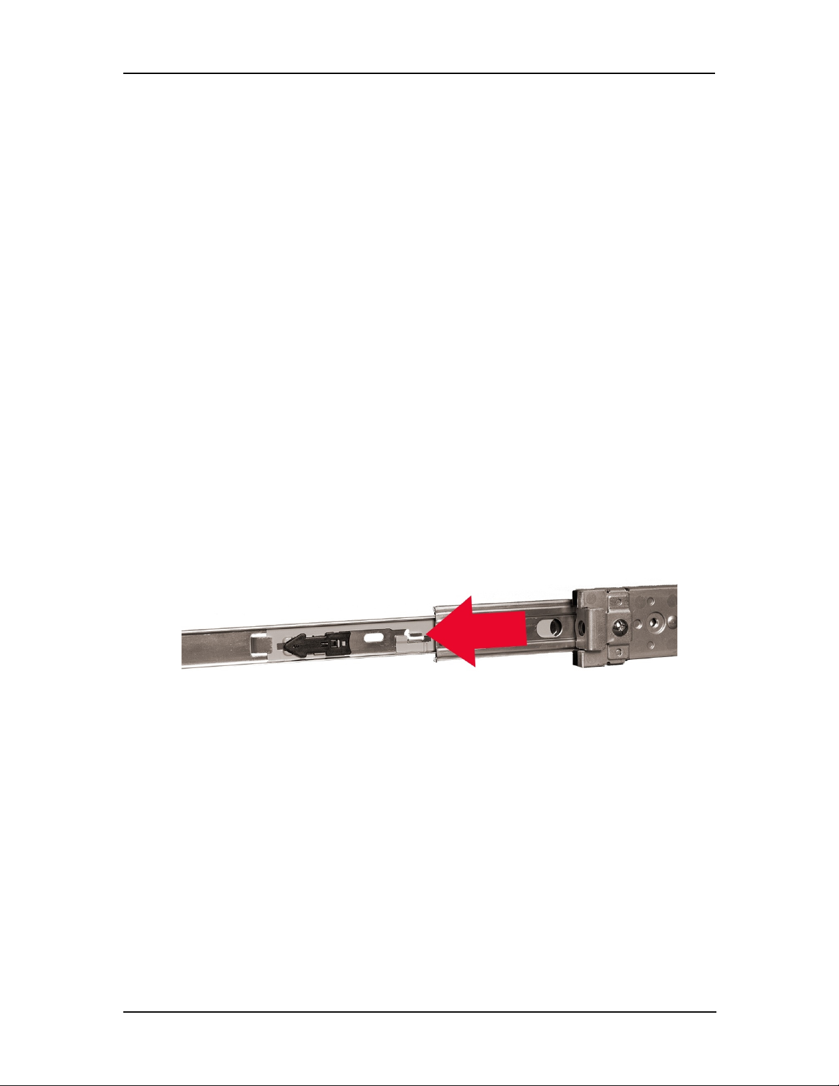
Installing the Inner Rails on the Appliance
1. Fully extend the right rail until all three rail segments are visible.
2. Push the rail-release arrow (located between the second and third extended rails)
forward and continue sliding until it is separated from the other two rail segments.
HX 4400 CHAPTER 3: Installation
16 ©2016 FireEye

Hardware Administration Guide Rack Installation
3. Align the inner rail notches with the pegs on the right side of the appliance.
4. Slide the rail toward the pegs.
©2016 FireEye 17
5. Insert the two screws to secure the inner rail to the appliance.
6. Repeat steps 1-5 for the left rail.
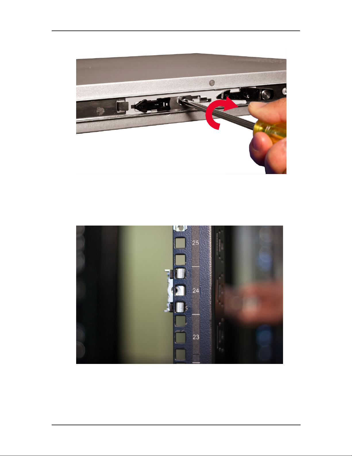
Installing the Outer Rails on the Rack
1. Press the black tabs of the right outer rail against the front rack column and insert
the hooks at the desired height.
HX 4400 CHAPTER 3: Installation
18 ©2016 FireEye
Hardware Administration Guide Rack Installation
2. Firmly press the rail into the rack to lock it in place.
3. Extend the rail until it reaches the rear rack column and insert the rail using the
same procedure described in the previous two steps.
4. Repeat steps 1-3 for the left outer rail.
5. Insert and tighten the screws at the rear of the rails to further secure them to the
rack.
Mounting the Appliance on the Rack
1. Align the inner rails installed on the appliance with the channels of the outer rails
installed on the rack.
©2016 FireEye 19
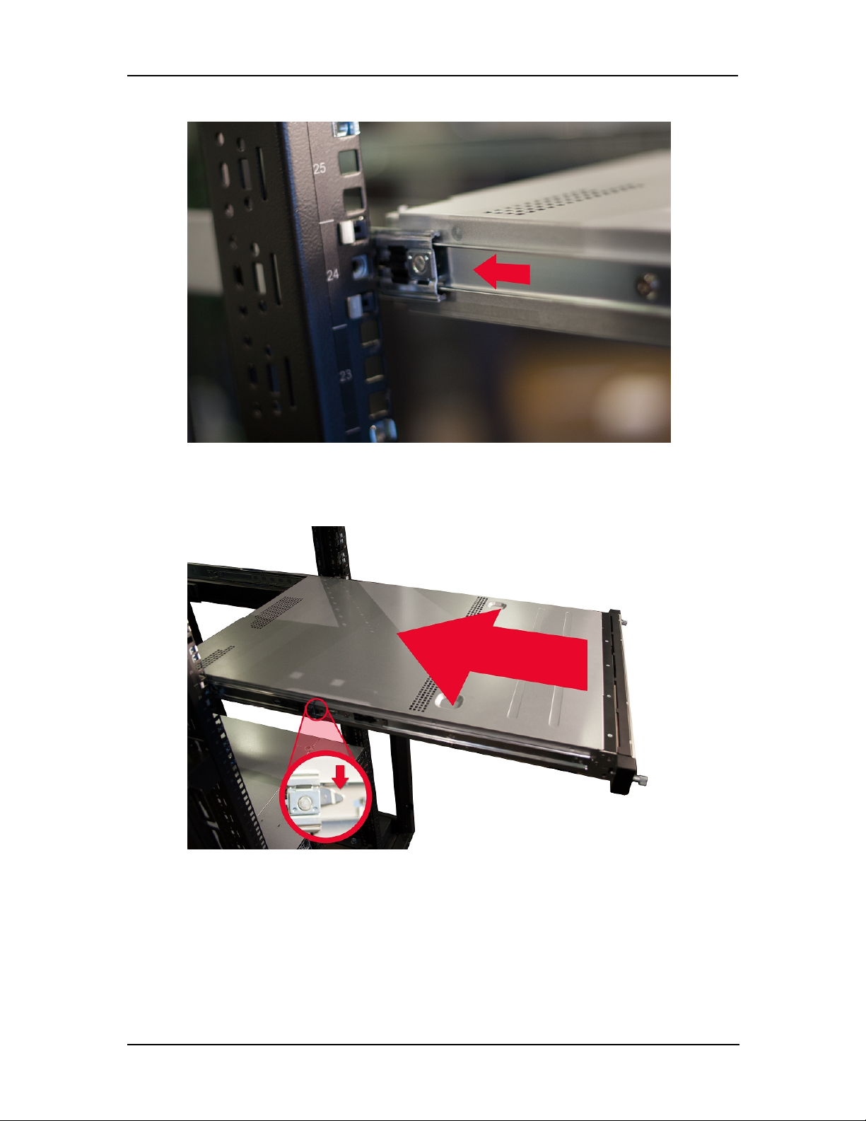
2. Slide the appliance halfway into the rack.
3. Press the rail-release notches down on both rails and slide the appliance fully into
the rack.
4. Tighten the thumbscrews located at the sides of the bezel to secure the appliance to
the rack.
HX 4400 CHAPTER 3: Installation
20 ©2016 FireEye
This manual suits for next models
1
Table of contents
Other Fire-Eye Test Equipment manuals

Popular Test Equipment manuals by other brands


Redtech
Redtech TRAILERteck T05 user manual

Venmar
Venmar AVS Constructo 1.0 HRV user guide

Test Instrument Solutions
Test Instrument Solutions SafetyPAT operating manual

Hanna Instruments
Hanna Instruments HI 38078 instruction manual

Kistler
Kistler 5495C Series instruction manual

Waygate Technologies
Waygate Technologies DM5E Basic quick start guide

StoneL
StoneL DeviceNet CK464002A manual

Seica
Seica RAPID 220 Site preparation guide

Kingfisher
Kingfisher KI7400 Series Training manual

Kurth Electronic
Kurth Electronic CCTS-03 operating manual

SMART
SMART KANAAD SBT XTREME 3G Series user manual

Agilent Technologies
Agilent Technologies BERT Serial Getting started